Note : Les descriptions sont présentées dans la langue officielle dans laquelle elles ont été soumises.
CA 02310279 2000-OS-30
4UT0 VENTILATION SYSTEM FOR VEHICLES AND CONTROL METHOD THEREOF
BACKGROUND OF THE INVENTION
Field of the Invention
The present invention relates to an auto ventilation system for
vehicles and a control method thereof, and more particularly to an auto
ventilation system for a vehicle and a control method thereof which are
adapted to maintain a fresh atmosphere in the interior of the vehicle.
Description of the Prior Art
In most cars, a device adapted to ventilate air from the interior
of the car in association with air conditioning is configured to be
manually started up in response to a manipulation by a driver. Only in
the case of specific vehicles, for example, deluxe cars, such a
ventilation device is configured to be automatically started up in an
engine start-up state.
Even in the latter case, however, the ventilation device does not
operate automatically in a state in which the engine is stopped. For
this reason, where only children or elderly and feeble persons having no
ability to manipulate the ventilation device are within the interior of
-1-
CA 02310279 2000-OS-30
the car in a state in which the ambient temperature is about 30C or
more, a mishap may occur due to a shortage of oxygen and a lapse of body
strength.
Furthermore, a mishap may occur when the driver or passengers are
s 1 eep i ng wh i 1 a the a i r cond i t i oner i s turned on i n summer or wh
i 1 a the
heater is turned on in winter.
In order to solve such problems, an auto ventilation device and a
control method thereof have been proposed by Daewoo Electronic Co. Ltd.
in Korea. They are disclosed in the Korean Patent 4pplic:ation No.
9 9- 2264 6 filed on September 30, 1997 in the name of Daewoo Electronic
Co. Ltd. in Korea. The disclosed ventilation device includes a fan
motor for blowing a flow of air, and a power window motor for opening
and closing vehicle power windows. Ln particular, the ventilation
devi ce i nc 1 udes a gas sensor un i t mounted at a des i red pos i t i on o
f the
vehicle and adapted to sense the amount of carbon dioxide existing in
the interior of the vehicle, thereby outputting an electrical sensor
indicative of the sensed carbon dioxide amount, a temperature sensor
uni t mounted at a des i red pos i t i on of the vehi c 1 a and adapted to
sense
the temperature of the interior of the vehicle, thereby outputting an
electrical signal indicative of the sensed temperature, and a control
unit for receiving the output signals from the gas sensor unit and
-2-
CA 02310279 2000-OS-30
temperature sensor unit, determining whether or not each of the received
electrical signals is more than an associated one of reference values,
and outputting a control signal when at least one of the electrical
signals is more than the associated reference value, thereby allowing
the s i de power w i ndows o f the veh i c 1 a to be opened to a des i red
extent
for an introduction of ambient air into the interior of the vehicle.
The ventilation device further includes an interface unit coupled to the
output terminal of the control unit and adapted to amplify a signal of a
low output level outputted from the control unit to a high output level.
The power window motor is coupled to the output terminal of the
interface unit so that it operates to open the side power windows to a
desired extent in response to the control signal from the control unit.
The fan motor is also coupled to the output terminal of the interface
uni t so that i t operates to i ntroduce ambi ent ai r i nto the i nteri or of
the vehicle in response to the control signal from the control unit.
However, use of such an auto vent i 1 at i on devi ce i s not frequent
because there are very few occas i ons that on 1 y ch i 1 dren or a 1 der 1 y
and
feeble persons having no ability to manipulate the ventilation device
are within the interior of the car in a state in which the ambient
temperature is about 30C or more. As a result, this auto ventilation
device exhibits a very low utility. Even normal adults cannot perfectly
-3-
CA 02310279 2000-OS-30
adjust various instruments associated with air conditioning to maintain
a fresh atmosphere in the interior of the vehicle without continuously
adjusting the environment controls. Thus, there is an inconvenience in
use.
SUMMARY OF THE LNU'ENTIO~
The present invention has been made in view of the above
mentioned problems, and an object of the invention is to provide an auto
ventilation system for a vehicle and a control method thereof which are
capable of maintaining a fresher atmosphere in the interior of the
vehicle, irrespective of the season.
In accordance with one aspect, the present invention provides an
auto ventilation system for a vehicle comprising a ventilation fan motor
mounted to a body of the vehicle and adapted to circulate air in the
interior of the vehicle, a duct solenoid installed in an air flow path
communicated with the ventilation fan motor and adapted to allow the air
flow path to communicate with the atmosphere, a power window motor
mounted to the vehicle body and adapted to open and close power windows
included in the vehicle, and an air conditioner mounted to the vehicle
body and adapted to supply air of a relatively low temperature to the
-4-
CA 02310279 2000-OS-30
interior of the vehicle, further comprising: a temperature sensing unit
installed in the interior of the vehicle and adapted to sense a
temperature in the interior of the vehicle, thereby generating a
corresponding temperature sensing signal; a gas sensing unit installed
in the interior of the vehicle in the vicinity of the temperature
sensing unit, the gas sensing unit serving to sense hazardous gas
existing in the interior of the vehicle, thereby generating a
corresponding gas sensing signal; a signal processing unit for
amplifying the signal outputted from the temperature sensing unit and
the signal outputted from the gas sensing unit to desired gains,
respectively, removing noise components from the amplified signals, and
outputting the resultant signals; a gear position sensing unit for
sensing a gear position of the vehicle, thereby outputting a gear
position sensing signal; an engine start-up sensing unit for sensing an
engine start-up state of the vehicle, thereby outputting an engine
start-up sensing signal; and drive control means for selectively driving
the air conditioner, the ventilation fan motor, the duct solenoid unit,
and the power window motor, based on the temperature sensing signal, the
gas sensing signal, the gear position sensing signal, and the engine
start-up sensing signal.
Preferably, the drive control means comprises a controller for
-5-
CA 02310279 2000-OS-30
comparing the temperature sensing signal, the gas sensing signal, the
gear position sensing signal, and the engine start-up sensing signal
with reference signals associated therewith, respectively, thereby
generating control signals in accordance with respective results of the
comparison, a fan motor driver for driving the ventilation fan motor in
response to an associated one of the control signals generated from the
controller when the gas sensing signal is higher than an associated one
of the reference signals, a solenoid driver for driving the duct
solenoid in response to the control signal generated from the controller
when the gas sensing signal is higher than the associated reference
signal, a window motor driver for driving the power window motor in
response to the control signal generated from the controller when the
gas sensing signal is higher than the associated reference signal, and
an air conditioner driver for driving the air conditioner in response to
an associated one of the control signals generated when the temperature
sensing signal is higher than an associated one of the reference signals
and when the vehicle is sensed to be in its engine start-up state of the
vehicle, thereby lowering the temperature in the interior of the
vehicle.
The controller preferably includes an external memory stored with
an algorithm for controlling the auto ventilation system.
-6-
CA 02310279 2000-OS-30
Preferably, the drive control means further comprises an
emergency lamp driver for turning on emergency lamps, included in the
vehicle, in a flickering fashion in response to the control signal
generated when the gas sensing signal is higher than the associated
reference signal, thereby outwardly informing of occurrence of an
emergency situation in the interior of the vehicle.
The auto ventilation system preferably further comprises command
input means coupled to the drive control means, the command input means
serving to input, to the drive control means, a command generated in
accordance with a manipulation by a user for an operation of the auto
ventilation system. The command input means may comprise a remote input
unit positioned at a position remote from the drive control means and
adapted to encode the command, and to transmit the command at a desired
frequency, and a command receiving unit electrically connected to the
drive control means and adapted to receive the command from the remote
input unit and to decode the received command in accordance with a
desired signal processing procedure.
In accordance with another aspect, the present invention provides
an auto ventilation control method for a vehicle including at least one
of a ventilation fan motor mounted to a body of the vehicle and adapted
to circulate air in the interior of the vehicle, a duct solenoid
CA 02310279 2000-OS-30
installed in an air flow path communicated with the ventilation fan
motor and adapted to allow the air flow path to communicate with the
atmosphere, a power window motor mounted to the vehicle body and adapted
to open and close power windows included in the vehicle, and an air
conditioner mounted to the vehicle body and adapted to supply air of a
relatively low temperature to the interior of the vehicle, comprising
the steps of: {,A) sensing a temperature in the interior of the vehicle,
thereby generating a corresponding temperature sensing signal; {B)
sensing hazardous gas existing in the interior of the vehicle, thereby
generating a corresponding gas sensing signal; {C) sensing a gear
position of the vehicle, thereby outputting a gear position sensing
signal; {D) sensing an engine start-up state of the vehicle, thereby
outputting an engine start-up sensing signal; and (E) driving the at
least one of the air conditioner, the ventilation fan motor, the duct
solenoid unit, and the power window motor, based on the temperature
sensing signal, the gas sensing signal, the gear position sensing
signal, and the engine start-up sensing signal.
Preferably, the step {E) comprises the steps of: comparing the
temperature sensing signal, the gas sensing signal, the gear position
sensing signal, and the engine start-up sensing signal with reference
signals associated therewith, respectively, thereby generating control
_g_
CA 02310279 2000-OS-30
signals in accordance with respective results of the comparison; driving
the ventilation fan motor in response to an associated one of the
control signals generated from the controller when the gas sensing
signal is higher than an associated one of the reference signals;
driving the duct solenoid in response to the control signal generated
from the controller when the gas sensing signal is higher than the
associated reference signal; driving the power window motor in response
to the control signal generated from the controller when the gas sensing
signal is higher than the associated reference signal; and driving the
air conditioner in response to an associated one of the control signals
generated when the temperature sensing signal is higher than an
associated one of the reference signals and when the vehicle is sensed
to be in its engine start-up state of the vehicle, thereby lowering the
temperature in the interior of the vehicle.
Preferably, the step {E~ further comprises the step of generating
at least one of visible and audible alarm signals in response to the
control signal generated when the gas sensing signal is higher than the
associated reference signal, thereby outwardly, thereby informing of
occurrence of an emergency situation in the interior of the vehicle.
BRIEF DESCRIPTION OF THE DRAWINGS
_g_
CA 02310279 2000-OS-30
The above objects, and other features and advantages of the
present invention will become more apparent after a reading of the
following detailed description when taken in conjunction with the
drawings, in which:
Fig. 1 is a block diagram illustrating an auto ventilation system
for a vehicle in accordance with the present invention.
Fig. 2 is a circuit diagram illustrating a sequence control
circuit according to the embodiment of Fig. l~ and
Fig. 3 is a flow chart illustrating an auto ventilation control
method for a vehicle in accordance with the present invention.
DESCRIPTION OF THE PREFERRED EMBODIMIENTS
Now, an auto ventilation system for a vehicle and a control
method thereof in accordance with the present invention will be
descr i bed i n deta i 1, i n con j unct i on w i th the annexed draw i ngs. F
i g. 1
illustrates an auto ventilation system for a vehicle in accordance with
the present invention. Fig. 2 is a circuit diagram illustrating a
sequence control circuit according to the embodiment of Fig. 1. Fig. 3
is a flow chart illustrating an auto ventilation control method for a
- 10 -
CA 02310279 2000-OS-30
vehicle in accordance with the present invention.
As shown in Fig, 1, the auto ventilation system, which is applied
to a vehicle including an engine (not shown), a chassis body {not shown)
constituting the outer body of the vehicle, and wheels (not shorn)
adapted to move the chassis body while being in rolling contact with the
ground, includes a ventilation fan motor {not shown) mounted within the
chassis body and adapted to circulate air in the interior of the
vehicle, and a duct opening/closing unit {not shown) mounted in an air
flow path along which air is supplied to the ventilation fan motor. The
duct opening/closing unit serves to supply air circulating in the
interior of the vehicle or ambient air by opening or closing a duct
communicated with the atmosphere. The auto ventilation system also
includes a power window motor {not shown) for opening and closing power
windows mounted to respective doors of the chassis body, and an air
conditioner {not shown) for supplying cold air to the interior of the
vehicle.
The auto ventilation system further includes a temperature
sensing unit 1 mounted in the interior of the vehicle and adapted to
sense the temperature of the interior of the vehicle, a signal
processing unit 20 for amplifying a temperature sensing signal outputted
from the temperature sensing unit 1 to a desired gain, removing noise
- 11 -
CA 02310279 2000-OS-30
components from the amplified temperature sensing signal, and then
outputting the resultant signal in the form of a digital signal, and a
drive control unit 30 for generating a drive signal for the air
conditioner, based on the digital temperature sensing signal outputted
from the signal processing unit 20. As shown in Fig. l, the signal
process i ng uni t 20 i nc 1 udes an ampl i f i er 2 adapted to ampl i fy an i
nput
signal to a desired gain, and a filter adapted to remove noise
components from the amplified signal.
The drive control unit 30 includes a controller 4 for receiving
the temperature sensing signal, indicative of the temperature of the
vehicle interior, from the signal processing unit 20, comparing the
temperature sensing signal with a reference signal indicative of a
predetermined reference cooling temperature, determining occurrence of
an emergency situation when the temperature sensing signal has a level
higher than that of the reference signal, and generating at least one
control signal, based on the result of the determination associated with
the occurrence of the emergency situation, and an air conditioner
controller 8 for controlling the air conditioner to supply cold air for
a decrease in the vehicle interior temperature under the control of the
controller 4.
The controller 4 is equipped with an external memory 9 stored
- 12 -
CA 02310279 2000-OS-30
with an algorithm for executing the above mentioned comparison and
determination procedures, and an algorithm for driving drivers, that is,
a fan motor driver 5, a duct solenoid 6, a window motor driver 7, and an
air conditioner driver 8.
A gas sensing unit 11 is also installed in the interior of the
vehi c I a at a pos i t i on spaced apart from the temperature lens i ng uni t
1
by a desired distance. The gas sensing unit 11 serves to sense
hazardous gas existing in the interior of the vehicle and to output a
corresponding sensing signal to the signal processing unit 20. When
the controller 4 of the drive control unit 30 recognizes generation of
hazardous gas, based on the sensing signal outputted from the gas
sensing unit 11, it determines occurrence of an emergency situation
irrespective of the vehicle interior temperature sensed by the
temperature sensing unit 1. In this case, the controller 4 conducts a
control for driving at least one of the ventilation fan motor, duct
opening/closing unit, and power window motor, thereby circulating
ambient air through the interior of the vehicle. That is, the
controller 4 outputs a control signal to at least one of the fan motor
driver 5, duct solenoid 6, and window motor driver 7. The controller 4
also serves to output a control signal to drive an emergency lamp driver
when it recognizes occurrence of an emergency situation based on the
- 13 -
CA 02310279 2000-OS-30
sens i ng s i gna 1 from the temperature lens i ng un i t 4 or gas sens i ng
uni t
11, thereby turn i ng on an emergency 1 amp i n a f 1 i cker i ng f ash i on
so as
to inform others in the vicinity of the car of the emergency situation.
An input unit 40 is coupled to the drive control unit 30 in order
to al 1 ow the user to i nput a des i red command to the dr i ve contro 1 uni
t
30. The input unit 40 includes a transmitter and a receiver. That is,
the input unit 40 includes a remote command transmitter 12 for encoding
a command, generated in accordance with a manipulation of the user and
associated with an auto ventilation operation of the ventilation system,
into a corresponding code, modulating the code into a signal with a
desired frequency, and transmitting the resultant signal. The input
unit 40 also includes a command receiver 50 for receiving the signal
transmitted from the remote transmitter 12, and decoding the received
signal in accordance with an appropriate signal processing procedure.
The remote transmitter 12 may be positioned at a position remote from
the system. The command receiver 50 includes an amplifier/detector 13,
a demodulator 14, and a decoder 15.
The drive control unit 30 is also connected to a gear position
sensing unit 16 adapted to sense the position of a speed change gear
included in the vehicle, so that it generates drive signals in
accordance with the current gear position. The drive control unit 30 is
- 14 -
CA 02310279 2000-OS-30
also coupled to an engine start-up unit 17, so that it recognizes an
engine start-up state of the vehicle, When the drive control unit 30
senses, based on an output signal from the gear position sensing unit
16, that the vehicle is in a running state, it determines that the
current state corresponds to a state in which the air conditioner can be
driven. In this state, if the vehicle interior temperature is higher
than the reference cooling temperature, the drive control unit 30 then
drives the air conditioner driver 8. Where the current gear position
corresponds to a neutral or parked position, the drive control unit 30
determines, based on an output signal from the engine start-up unit 17,
whether or not the engine is in its start-up state. When the engine is
in its start-up state, the drive control unit 30 repeatedly conducts the
above control procedure. If not, the drive control unit 30 controls the
engine start-up unit 17 to start up the engine. Thereafter, the drive
control unit 30 drives the air conditioner driver 8 in order to control
the vehicle interior temperature.
.A heater driver 18 adapted to drive a heater (not shown) is also
included in the drive control unit 30. Where the temperature sensed by
the temperature sensing unit 1 is lower than a reference heating
temperature in winter, the drive control unit 30 drives the heater
driver 18 in order to increase the vehicle interior temperature,
- 15 -
CA 02310279 2000-OS-30
The auto ventilation system having the above mentioned
configuration according to the present invention may be implemented in
accordance with an embodiment illustrated in Fig. 2. In Fig. 2,
elements respectively corresponding to those in Fig. 1 are denoted by
the same reference numerals. Referring to Fig. 2, the auto ventilation
system includes a power supply unit including an power generator, a
battery for accumulating power generated from the power generator, and a
fuse for preventing the supply of overload power, a command receiver 50
for receiving a command from the remote command transmitter 12, and
conducting an amplification, detection, demodulation, and decoding for
the received command, and a controller 4 for conducting a control
operation in response to the command received from the command receiver
50. The controller 4 receives sensing signals respectively outputted
from the temperature sensing unit 1 and the gas sensing unit 11, and
compares each of the sensing signals with an associated reference
signal, thereby controlling the vehicle interior temperature or an air
ventilation. That is, the controller 4 controls the fan motor driver 5,
the window motor driver 7, and the air conditioner driver 8, The auto
ventilation system also includes a power window motor activated by the
fan motor driver 5, window motor driver 7, or air conditioner driver 8,
a compressor motor for the ai r condi t i oner, and a fan motor. The auto
- 16 -
CA 02310279 2000-OS-30
ventilation system further includes a heater driver 18 for driving a
heater adapted to supply air of a relatively high temperature in winter.
although not shown, the controller 4 further includes a duct solenoid 6
for driving the duct opening/closing unit tnot shown) installed in the
air flow path of the ventilation fan motor in order to achieve a smooth
and efficient ventilation operation of the ventilation fan motor.
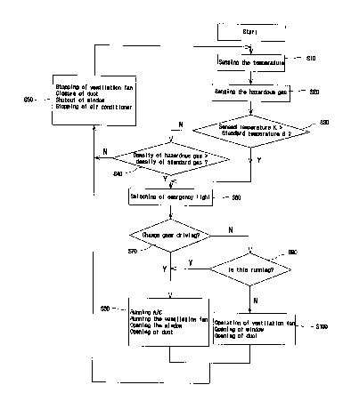
Referring to Fig. 3, an auto ventilation control method according
to the present i nvent i on i s i 1 1 us trated wh i ch i s carr i ed out us i
ng the
above mentioned auto ventilation system. In accordance with this auto
vent i 1 at i on contro 1 method, as shown i n F i g. 3, the temperature of
the
interior of the vehicle is first sensed by the temperature sensing unit
1 which, in turn, sends the resultant sensing signal to the drive
control unit 30 (Step S10). The gas sensing unit 11 also senses the
concentration of hazardous gas existing in the interior of the vehicle,
and sends the resultant sensing signal to the drive control unit 30
(Step S20). Based on the received temperature data, the drive control
unit 30 determines whether or not the sensed temperature is higher than
a predetermined reference temperature (Step S30). Where it is
determined at step S30 that the sensed temperature is higher than the
reference temperature, the drive control unit 30 then determines, based
on the received concentration data, whether or not the sensed hazardous
- 17 -
CA 02310279 2000-OS-30
gas concentration is higher than an experimentally predetermined
reference concentration (Step S60). When it is determined at step S60
that the sensed hazardous gas concentration is not higher than the
reference concentration, the drive control unit 30 then determines,
based on an output signal from the gear position sensing unit 16,
whether the current gear position corresponds to a running position, a
stop position, a neutral position, or a parked position (Step S70).
49here it is determined at step S70 that the current gear position does
not correspond to the running position, it is then determined whether or
not the engi ne i s i n a start-up state ( Step S80 ) . Under the condi t i on
in which the engine is in its start-up state, the air conditioner driver
is activated to drive the air conditioner (Step 5100). However, where
the current gear position corresponds to the stop, neutral or parked
position or where the engine is not in its start-up state, start-up
power is supplied to the engine start-up unit 17, thereby starting up
the engine start-up unit 17 (Step S90). Following the start--up of the
engine, the air conditioner is driven at step 5100.
When it is determined at step S60 that the sensed hazardous gas
concentration is higher than the reference concentration under the
condition in which the sensed temperature is higher than the reference
temperature, the drive control unit 30 determines occurrence of an
- 18 -
CA 02310279 2000-OS-30
emergency situation, so that it turns on the emergency lamp in a
flickering fashion (Step 5110). The drive control unit 30
simultaneously determines whether the current gear position corresponds
to a running position, a stop position, a neutral position, or a parked
position {Step 5120). Where it is determined at step 5120 that the
current gear position does not correspond to the running position, the
air conditioner driver 5 is activated to drive the air conditioner (Step
5130). At step 5130, the fan motor driver 5, duct solenoid 6, and
window motor driver 7 are also driven. That is, a ventilation is
conducted as the ventilation fan motor is driven. In accordance with
the driving of the window drive motor, at least one of the power windocvs
is opened. Also, the duct openinglclosing unit installed in the air
flow path of the ventilation fan is driven, thereby rapidly discharge
the air existing in the interior of the vehicle.
Where it is determined at step 5120 that the current gear position
corresponds to the stop, neutral or parked position, it is determined
whether or not the engine is in its start-up state {Step 5140). When
the engine is not in its start-up state, all drivers except for the air
conditioner are activated {Step S150). That is, the fan motor driver 5,
duct solenoid 6, and window motor driver 7 are driven. That is, a
ventilation is conducted as the ventilation fan motor is driven. In
- 19 -
CA 02310279 2000-OS-30
accordance with the driving of the window drive motor, at least one of
the power windows is opened, Also, the duct opening/closing unit
installed in the air flow path of the ventilation fan is driven to open
the duct, thereby rapidly discharge the air existing in the interior of
the vehicle.
On the other hand, where it is determined at step S30 that the
sensed temperature is not higher than a predetermined reference
temperature, it is then determined whether or not the sensed hazardous
gas concentration is higher than the reference concentration (Step S40).
t'Jhen it is determined at step S40 that the sensed hazardous gas
concentration is higher than the reference concentration under the
condition in which the sensed temperature is not higher than the
reference temperature, the drive control unit 30 determines occurrence
of an emergency s i tuat i on, so that i t turns on the emergency 1 amp i n a
flickering fashion (Step S160). The drive control unit 30
simultaneously activates all drivers except for the air conditioner
(Step S170). That is, the fan motor driver 5, duct solenoid 6, and
window motor driver 7 are driven. That is, a ventilation is conducted
as the ventilation fan motor is driven. In accordance with the driving
of the window drive motor, at least one of the power windows is opened.
4lso, the duct opening/closing unit installed in the air flow path of
- 20 -
CA 02310279 2000-OS-30
the ventilation fan is driven to open the duct, thereby rapidly
discharge the air existing in the interior of the vehicle. On the other
hand, where it is determined at step S40 that the sensed hazardous gas
concentration is not higher than the reference concentration, the drive
control unit 30 conducts a control for stopping the ventilation fan,
closing the opened power windows, closing the duct, and stopping the air
conditioner.
The above mentioned ventilation system may be controlled to
execute an auto ventilation operation prior to sensing operations for
temperature and hazardous gas. In particular, this may be achieved in a
remote-controlled fashion. When a user command associated with an auto
ventilation is generated from the remote transmitter manipulated by the
user, the above mentioned algorithm is executed. This algorithm is
stored in the external memory 9, as mentioned above.
As apparent from the above description, the present invention
provides an auto ventilation system for a vehicle and a control method
thereof which are capable of outwardly discharging air existing in the
interior of the vehicle when the atmosphere in the interior of the
vehicle is severely deteriorated, irrespective of the season (summer or
winter), while simultaneously forcibly introducing refresh ambient air
into the interior of the vehicle or supplying cold air of a desired low
- 21 -
CA 02310279 2000-OS-30
temperature, thereby maintaining a fresh atmosphere in the interior of
the vehicle. Accordingly, it is possible to prevent a mishap of the
driver or passengers within the interior of the vehicle, thereby
protecting the driver and passengers. In accordance with the present
invention, the ventilation operation is conducted depending on the gear
state and start-up state of the vehicle. Accordingly, it is possible to
effectively cope with and surely remove an emergency situation occurring
in the interior of the vehicle. Since it is unnecessary for the user to
directly manipulate various elements for ventilation, the auto
ventilation system of the present invention provides a maximized
convenience in use, so that it contributes to a safe vehicle driving.
Although the preferred embodiments of the invention have been
disclosed for illustrative purposes, those skilled in the art will
appreciate that various modifications, additions and substitutions are
possible, without departing from the scope and spirit of the invention
as disclosed in the accompanying claims.
- 22 -
CA 02310279 2000-OS-30
Fig. 1
1: TEMPERATURE SENSING UNIT
2: ,AMPL1FIER
3: FILTER
4: CONTROLLER
5: F.AN MOTOR DRIVER
6: DUCT SOLENOID
7: WINDOW MOTOR DRIVER
8: :AIR CONDITIONER DRIVER
9: EXTERNAL MEMORY
10: EMERGENCY LAMP DRLVER
11: GAS SENSING LNIT
12: REMOTE TRANSMITTER
13: AMPLIFIER/DETECTOR
14: DEMODULATOR
15: DECODER
16: GEAR POSITION SENSING UNIT
17: ENGINE START-UP UNIT
18: HEATER DRLVER
- 32 -
CA 02310279 2000-OS-30
Fig. 2
POWER SUPPLY UNIT
POWER GENERATOR
BATTERY
Ease box. FUSE BOX
TEMPERATURE SENSING SIGNAL
GAS SENSING SIGNAL
CONTROLLER
VENTILATION FAN MOTOR
WINDOW
COMPRESSION MOTOR FOR AIR CONDITIONER
HEATER
16: GEAR POSITION SENSING UNIT
17: ENGINE START-UP UNIT
50: COMMAND RECEIVER
Fig. 3
START
510: SENSE TEMPERATURE
520: SENSE HAZARDOUS GAS
530: SENSED TEMPERATURE ~ REFERENCE TEMPERATURE?
- 33 -