Note : Les descriptions sont présentées dans la langue officielle dans laquelle elles ont été soumises.
CA 02311060 2000-06-08
CANOPY STRUCTURE FOR TWO WHEELED VEHICLES
The present invention relates to the field of accessories for vehicles and
more
particularly, is concerned with a canopy structure for two wheeled vehicles.
BACKGROUND OF THE INVENTION
As is well known in the art, two wheeled vehicles enjoy a substantial
popularity. The two wheeled vehicles include bicycles which are ridden for
pleasure
and motorized vehicles such as scooters and motor bikes.
The weather is an important factor in the use of such vehicles. Rain, for
example, can make the use of such two wheeled vehicles somewhat unpleasant.
Even
the sun, under certain conditions, can be unpleasant for certain users due to
the health
risks involved due to excess UV exposure.
The users of the vehicles have resorted to either attempting to dress for the
climatic conditions of the particular occasion or alternatively, forgoing
riding their
vehicles.
The prior art is replete with various assemblies which have been developed to
circumvent the above mentioned disadvantages when riding two wheeled vehicles.
Most of the known structures have rigid frames or attachments to the vehicle
along
with a cover panel which is attached to the frame structure for covering the
users of
the vehicle.
Such prior art cover assemblies have not met with any commercial success,
which is believed to be due to the difficulty in assembling of the structures
and their
interference with operation of the vehicle.
CA 02311060 2000-06-08
Exemplary of the teachings of the prior art is U.S. Patent 4,778,214 which
discloses a vehicle shield including a front strut, a rear strut, a top cover
and two
bracket plates. The shield is mounted on the front handle members and on the
rear
portion of the vehicle such that the top cover thereof can function to
minimize the
effects of wind and adverse weather conditions during use of the vehicle.
A further structure known in the prior art is seen in U.S. Patent 4,681,362 to
Taylor issued July 21, 1987 and which shows a canopy removably mounted on a
vehicle and includes a pair of tubes that are fastened to the body of the
vehicle onto
the windshield thereof. The rear flap of the canopy includes a plurality of
air vents to
provide aerodynamic stability to the vehicle at high speed.
A still further structure is known from U.S. Patent 5,072,987 to Marshall
Allen
issued December 19, 1991, and which teaches a retractable roof for two wheeled
vehicles including a flexible water proof canopy removably supported by a
tubular
frame. The frame includes a stationary base portion and an overhead portion
including a front bow, a central bow and a rear bow all of which can be
pivoted from
an upright position to a lower position parallel to the base portion and
behind the seat.
The central bow includes telescopic elements which allow it to be shortened
when in
the lowered position.
SUMMARY OF THE INVENTION
It is an object of the present invention to provide a improved canopy
structure
for two wheeled vehicles.
-2-
CA 02311060 2000-06-08
It is a further object of the present invention to provide a canopy structure
for
two wheeled vehicles such as bicycles, scooters, motorcycles and the like
which will
provide protection from the weather elements and which canopy structure can be
customized depending on the specific needs.
It is a further object of the present invention to provide a canopy structure
for
two wheeled vehicles and which canopy structure is convertible and collapsible
and
includes both top and side protection.
According to one aspect of the present invention, there is provided a canopy
structure for a vehicle having two wheels, the canopy structure comprising a
front
vertical frame having a front vertical frame upper end and a front vertical
frame lower
end, a rear vertical frame having a rear vertical frame upper end and a rear
vertical
frame lower end, a horizontal frame extending between and connected to an
upper
end of each of the front vertical frame and the rear vertical frame, front
vertical frame
mounting means connected to a lower end of the front vertical frame, rear
vertical
frame mounting means connected to a lower end of the rear vertical frame, a
protective panel extending across the horizontal frame, and means for
adjusting the
height of the front vertical frame mounting means.
Preferably, the canopy structure includes means for adjusting the height and
which means may conveniently comprise a spacing member and a cooperating
sleeve
for receiving the spacing member.
-3-
CA 02311060 2000-06-08
BRIEF DESCRIPTION OF THE DRAWINGS
Having thus generally described the invention, reference will be made to the
accompanying drawings illustrating an embodiment thereof, in which:
Figure 1 is a perspective view of a vehicle canopy according to one aspect of
the present invention, the vehicle canopy being shown mounted on a motor
scooter;
Figure 2 is a perspective view of the vehicle canopy of Figure 1 including the
mounting of transparent protective side and end panels thereon;
Figure 3 is a side elevational view of the vehicle canopy of Figure 2;
Figure 4 is a front elevational view thereof;
Figure 5 is a top plan view thereof;
Figure 6 is a bottom plan view thereof;
Figure 7 is a sectional view taken along the line 7-7 of Figure 5;
Figure 8 is a perspective view illustrating a further embodiment of a vehicle
canopy used in conjunction with a bicycle;
Figure 9 is a perspective view of the vehicle canopy of Figure 8 including the
mounting of transparent panels thereon;
Figure 10 is a side elevational view of the vehicle canopy for the bicycle;
Figure 11 is a view of the front wall thereof; and
Figure 12 is a side elevational view of the front wall portion.
DESCRIPTION OF THE PREFERRED EMBODIMENTS
Referring to the drawings in greater detail and by reference characters
thereto,
there is illustrated in Figure 1 a vehicle canopy according to one embodiment
of the
-4-
CA 02311060 2000-06-08
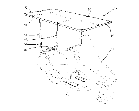
present invention and which is generally designated by reference numeral 10.
Vehicle
canopy 10 is designed to be mounted on a motor bike which is shown in phantom
outline and which is generally designated by reference character M.
Vehicle canopy 10 includes an upper horizontal frame structure generally
designated by reference numeral 14. For ease of description, the structure
will
employ the terms horizontal and vertical to mean those components which are
normally in that position when on the vehicle, but which terms are not
intended to be
limiting of the invention.
Horizontal frame structure 18 is comprised of a first side longitudinally
extending frame member 18 and a second side longitudinally extending frame
member 20. Frame members 18 and 20 are parallel and there is also provided a
parallel intermediate frame member 22. The outer extremities of horizontal
frame
structure 14 are defined by a first end frame member 24 extending between side
frame
members 18 and 20 and a second end frame member 26 likewise extending between
side frame members 18 and 20. A pair of transverse frame members 28 and 30
likewise extend between side frame members 18 and 20 and are parallel to end
frame
members 24 and 26.
Mounted on horizontal frame 14 is a horizontal panel 32 which may be formed
of any suitable material and preferably, is formed of a water resistant or
water
repellant material. However, other materials may be utilized - i.e. a mesh
type of
material to reduce the amount of light transmitted therethrough may be
desirable
under certain conditions.
-5-
CA 02311060 2000-06-08
As may be seen in Figure 7, horizontal panel 32 may be secured about the
various frame members by means of an adhesive strip having a hook and eye
arrangement - a plurality of hooks 34 are designed to engage eyes 36 in the
type of
attachment marketed under the Trademark VELCRO.
Vehicle canopy 10 also includes a rear vertical structure generally designated
by reference numeral 40. Rear vertical frame structure 40 includes a pair of
spaced
apart vertical struts 42 and 44 and which are joined together at their bottom
edges by
a transverse strut 46.
For purposes of attaching rear vertical frame 40 to the motor bike M, there
are
provided a pair of legs 48 each having an attachment pad 50 thereon. Bolts 52
may
then be used to secure pads 50 to an appropriate substrate surface of the
motor
bike M.
The vehicle canopy also includes a front vertical frame generally designated
by
reference numeral 58. Front vertical frame 58 includes first and second
vertical
struts 60 and 62 with a lower transverse strut 64 connecting the lower ends of
vertical
struts 60 and 62.
A spacing strut 66 is connected to transverse strut 64 and is designed to fit
within a vertical sleeve 68. A series of apertures 70 are formed in both
spacing
strut 66 and vertical sleeve 68 such that the height or vertical length may be
adjusted
depending on the particular vehicle by locking spacing strut 66 and vertical
sleeve 68
in a desired position by a pin.
-6-
CA 02311060 2000-06-08
Vertical frame 58 is mounted by means of an inverted U-shaped mounting
member generally designated by reference numeral 72. Pads 74 are provided on
the
bottom surface of inverted U-shaped mounting member 72 with apertures 76 being
formed therein to receive fastening members 78.
As will seen in Figure 2, when in use, the canopy structure may include a
transparent front panel 80, a transparent rear panel 82, and transparent side
panels 84.
Preferably, all of the panels are secured by means of a hook and loop fastener
of the
type previously discussed.
Turning to Figures 8 to 12, there is illustrated a modified embodiment of the
canopy structure which is suitable for use with a conventional bicycle, shown
in
phantom outlines, and generally designated by reference character B.
In this embodiment, similar reference numerals with a prime are employed for
similar components compared to the version illustrated in Figures 1 to 7.
The vehicle canopy 10' includes a horizontal frame 14' having a horizontal
panel 32' secured thereto. Similarly, there is provided a rear vertical frame
40' and a
front vertical frame 58' with strut 62'.
In this embodiment, there is provided a front reinforcing strut 88 and rear
reinforcing struts 90 and 92. These reinforcing struts may be provided due to
the
lighter weight structural material employed.
At the front, there is provided a connecting assembly 94 which is comprised of
vertical sleeve portion 96, horizontal strut 98 and vertical strut 100. The
arrangement
is such that strut 62' will fit within sleeve 96 while vertical strut 100 will
fit within
CA 02311060 2000-06-08
sleeve 68'. In this respect, it will noted that the sleeve 68' has a pivot
point 6T such
that it may be moved out of the way as shown in phantom outline in Figure 10
when
the roof structure is removed.
Also, in this embodiment, there may be provided a front panel 102 which is
pivotably connected at 104 to the strut 62 and horizontal frame 14'. As shown
in
Figure 12, a spacing member 106 may be used to interconnect the bottom of
front
panel 102 to connecting assembly 94 to maintain a distance therebetween and
provide
for ventilation.
In addition to front panel 102, there may be provided a rear panel 110. When
desired, a side panel 108 may be provided and which will extend over both the
rear
panel 110 and a front panel.
In different embodiments, various arrangements may be employed for storage
of the device. Thus, for example, horizontal frame 14 and horizontal panel 32
may be
designed to be readily knocked down for compact storage. To do so, a sliding
tube
arrangement may be utilized. Similarly, if desired, adjustability of the rear
vertical
frame may be provided in a manner similar to that employed for the front
vertical
frame.
It will be understood that the above described embodiment is for purposes of
illustration only and changes or modifications may be made thereto without
departing
from the spirit and scope of the present invention.
_g_