Sélection de la langue

Search

Sommaire du brevet 2311241 

Énoncé de désistement de responsabilité concernant l'information provenant de tiers

Une partie des informations de ce site Web a été fournie par des sources externes. Le gouvernement du Canada n'assume aucune responsabilité concernant la précision, l'actualité ou la fiabilité des informations fournies par les sources externes. Les utilisateurs qui désirent employer cette information devraient consulter directement la source des informations. Le contenu fourni par les sources externes n'est pas assujetti aux exigences sur les langues officielles, la protection des renseignements personnels et l'accessibilité.

Disponibilité de l'Abrégé et des Revendications

L'apparition de différences dans le texte et l'image des Revendications et de l'Abrégé dépend du moment auquel le document est publié. Les textes des Revendications et de l'Abrégé sont affichés :

  • lorsque la demande peut être examinée par le public;
  • lorsque le brevet est émis (délivrance).
(12) Demande de brevet: (11) CA 2311241
(54) Titre français: SECHOIR A AIR CHAUD
(54) Titre anglais: HOT AIR DRYER
Statut: Réputée abandonnée et au-delà du délai pour le rétablissement - en attente de la réponse à l’avis de communication rejetée
Données bibliographiques
(51) Classification internationale des brevets (CIB):
  • F26B 25/04 (2006.01)
  • F26B 03/06 (2006.01)
  • F26B 17/20 (2006.01)
(72) Inventeurs :
  • LUKER, WILLIAM A. (Etats-Unis d'Amérique)
(73) Titulaires :
  • INC. INTERNATIONAL TECHNOLOGY SYSTEMS
(71) Demandeurs :
  • INC. INTERNATIONAL TECHNOLOGY SYSTEMS (Etats-Unis d'Amérique)
(74) Agent:
(74) Co-agent:
(45) Délivré:
(22) Date de dépôt: 2000-06-09
(41) Mise à la disponibilité du public: 2000-12-28
Licence disponible: S.O.
Cédé au domaine public: S.O.
(25) Langue des documents déposés: Anglais

Traité de coopération en matière de brevets (PCT): Non

(30) Données de priorité de la demande:
Numéro de la demande Pays / territoire Date
09/519,368 (Etats-Unis d'Amérique) 2000-03-06
60/140,949 (Etats-Unis d'Amérique) 1999-06-28

Abrégés

Abrégé anglais


A hot air slurry dryer having a cylindrical housing with
a central shaft rotatably mounted in the housing. Material to
be dried moves from an upstream end of the housing to an outlet
at a downstream end. A hot air inlet is connected to the
upstream end of the housing preferably at an upstream end wall.
A material inlet is open to the side wall of the housing
downstream of the hot air inlet. The shaft carries means for
breaking up the moist material introduced into the housing and
mixing it with the hot air. In a preferred embodiment a drum is
carried by the shaft at the inlet end of the cylindrical
housing. The drum carries a plurality of agitator blades that
pass close by the interior surface of the side wall of the
housing.

Revendications

Note : Les revendications sont présentées dans la langue officielle dans laquelle elles ont été soumises.


9
IN THE CLAIMS
The embodiments of the invention in which an exclusive
property or privilege is claimed are defined as follows:
1. A hot air dryer for drying a wet material, including:
an elongate dryer housing having a cylindrical side wall
defining a drying chamber, with an upstream end and a
downstream end;
an upstream end wall closing the upstream end of the
housing;
a shaft mounted in the housing parallel to the
longitudinal axis thereof and mounted for axial rotation in the
chamber;
means for axial rotation of the shaft in the chamber;
a hot air inlet to the housing at the upstream end of the
chamber;
an outlet on the housing at the downstream end of the
chamber for discharge of material that has been dried by the
hot air;
a material inlet pipe connected to the housing and open to
the drying chamber at a material inlet opening that is located
downstream of the hot air inlet so that wet material introduced
into the housing will mix with hot air introduced at the hot
air inlet and move downstream toward the outlet;
means on the shaft rotatable with the shaft for mixing the
hot air and wet material as it moves downstream in the chamber.

10
2. The dryer of claim 1 wherein:
the hot air inlet is connected to the upstream end wall.
3. The dryer of claim 2 wherein:
the means on the shaft for mixing the hot air and wet
material includes a plurality of retention paddles mounted on
the shaft, said paddles having tips that pass close by the
interior side wall of the housing upon rotation of the shaft.
4. The dryer of claim 3 including:
at least one wall mounted air dam fixed to the interior
side wall surface of the housing.
5. The dryer of claim 3 including:
at least one shaft mounted air dam fixed to the shaft.
6. The dryer of claim 2 including:
a drum mounted on the shaft near the upstream end of the
housing positioned in intercepting relationship to the material
inlet, said drum having a diameter substantially spanning most
of the diameter of the chamber of the housing;
a plurality of agitator blades mounted on the surface of
the drum positioned to sweep close by the interior side wall
surface of the housing upon rotation of the shaft.
7. The dryer of claim 6 wherein:
the agitator blades are mounted in a spiral pattern on the
drum.
8. The dryer of claim 6 including:
a plurality of paddles mounted on the shaft between the

11
upstream end of the drum and the upstream end wall of the
housing.
9. The dryer of claim 8 wherein:
said agitator blades are mounted on the drum in a spiral
pattern.
10. The dryer of claim 6 wherein:
the means on the shaft for mixing the hot air and the wet
material includes a plurality of retention paddles mounted to
the shaft downstream of the drum, said paddles having tips that
pass close by the interior side wall surface of the housing
upon rotation of the shaft.
11. The dryer of claim 10 including:
at least one wall mounted air dam fixed to the interior
side wall surface of the housing.
12. A hot air dryer for drying a wet material,
including:
an elongate dryer housing having a cylindrical side wall
defining a dryer chamber, with an upstream end and a downstream
end;
an upstream end wall closing the inlet end of the housing;
a shaft mounted in the housing parallel to the
longitudinal axis thereof and mounted for axial rotation in the
chamber;
means for rotation of the shaft in the chamber;
a hot air inlet to the housing at the upstream end of the

12
chamber;
an outlet on the housing at the downstream end of the
chamber for discharge of material that has been dried by the
hot air;
a material inlet to the housing open to the chamber at the
upstream end thereof for introduction of wet material into the
drying chamber;
a drum mounted to the shaft near the upstream end of the
housing, said drum having a diameter substantially spanning
most of the diameter of the chamber of the housing;
a plurality of agitator blades mounted on the surface of
the drum positioned to sweep close by the interior side wall
surface of the housing upon rotation of the shaft; and
a plurality of retention paddles mounted on the shaft
downstream of the drum having blades with tips that sweep close
by the interior side wall surface of the housing upon rotation
of the shaft.
13. The dryer of claim 12 wherein:
the agitator blades are mounted in a spiral pattern on the
drum.

Description

Note : Les descriptions sont présentées dans la langue officielle dans laquelle elles ont été soumises.

CA 02311241 2000-06-09
2
Cross Reference to a Related Application
' This application claims the benefit of U. S. Provisional
Patent Application Serial Number 60/140,949 filed June 6, 1999.
Background of the Invention
A hot air dryer with a cylindrical housing is shown and
described in U.S. Patent No. 5,570,517 issued November 5, 1996
the disclosure of which is incorporated herein by reference.
That dryer has a cylindrical housing. A rotatable shaft
extends through the housing. The housing has an inlet end for
admitting material to be dried and hot air to dry it. The
inlet end of the shaft carries disks that carry scraper blades .
The scraper blades are mounted to scrape the inside wall of the
housing. The last upstream disk carries end wall scraper
blades that scrape the inlet end wall of the housing. The
scraper blades prevent material that enters the housing from
adhering and remaining on the side and end wall of the housing.
The remainder of the shaft carries retention paddles. Shaft
mounted and wall mounted air dams are located along the length
of the housing. A discharge opening is at the outlet end of
the housing for discharge of material that is drier than it was
when it entered the inlet end.
The end wall scrapers are necessitated by the location of
the material inlet at the end wall of the housing. Material
tends to collect on the end wall and must be removed.
Elimination of these end wall and side wall scrapers is
desirable in terms of simplifying the structure and reducing

CA 02311241 2000-06-09
3
maintenance requirements.
In addition, material tends to accumulate between the
disks. This material will eventually dry and, in some
instances, burn. Elimination of this accumulation region is
desirable.
SUHIMARY OF THE INVENTION
The invention pertains to an improved hot air material or
slurry dryer of the type discussed above but wherein a product
inlet is connected to the side of the cylindrical housing as
opposed to the end wall. The end wall is no longer a problem
in terms of the formation of a build-up of material that needs
to be removed. In one preferred embodiment a drum is mounted
toward the upstream end of the shaft. The drum carries a
plurality of agitator blades to agitate the incoming material
to dry it . The agitator blades can be arranged in a spiral
pattern about the drum in order to influence downstream
movement of subject material. Retention paddles can be mounted
along the remainder of the shaft.
IN THE DRAWINGS
Figure 1 is a top plan view of a dryer according to the
invention;
Figure 2 is a side elevational view of the dryer shown in
Figure 1;
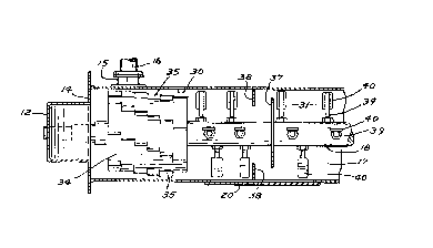
Figure 3 is side elevational view of the dryer of Figure
1 showing the side opposite that shown in Figure 2;
Figure 4 is an enlarged sectional view of a portion of the

CA 02311241 2000-06-09
4
dryer of Figure 2 taken along the line 4-4 thereof;
Figure 5 is another enlarged sectional view of a portion
of the dryer of Figure 2 taken along the line 5-5 thereof; and
Figure 6 is a sectional view of the upstream end of the
dryer like that of Figure 4 showing a modification.
DESCRIPTION OF A PREFERRED EMBODIMENT
A dryer according to a preferred embodiment of the present
invention is similar in many respects to the dryer shown and
described in U.S. Patent No. 5,570,517 referenced above. One
of the significant differences is that the dryer of the present
invention has a material inlet on the side of the dryer housing
as opposed to being located on the inlet end wall. Problems
with respect to the introduction of material at the inlet end
wall are eliminated.
A dryer of the present invention is indicated at 10 in the
drawings, and includes an elongate cylindrical dryer housing 11
supported on a stand or frame 13 and having a drying chamber
17. The inlet or upstream end of the dryer is on the left in
Figures 1 and 2. A hot air duct 12 is connected to the
upstream end wall 14 of housing 11 for introduction of hot air
into the drying chamber 17. Hot air duct 14 connects to a
suitable hot air source such as a furnace (not shown).
A material inlet is connected to the side of the dryer
housing 11 and open to chamber 17. The material inlet is
located to introduce wet material usually in a slurry form,
into the dryer housing downstream of the upstream end wall 14.

CA 02311241 2000-06-09
A material inlet fitting 15 is attached to the side of the
dryer housing 11 and open to chamber 17 at a material inlet
opening 15A. A material inlet pipe 16 is connected to the
inlet fitting 15. The other end of the material inlet pipe 16
5 is connected to a supply of material to be dried. An auger
(not shown) can optionally be mounted in the inlet pipe 16 for
movement of wet material into the dryer housing 11.
A shaft 18 is centrally mounted in housing 11 along the
longitudinal axis thereof for axial rotation. An upstream
outboard end 19 of shaft 18 extends out of dryer housing ll
through inlet end wall 14. The end 19 of shaft 18 is supported
by a pillow block bearing 21. The opposite or downstream end
22 of shaft 19 outboard of an outlet end wall 23 of dryer
housing 11 is supported by another pillow block bearing 24.
Shaft 18 is rotated by an electric motor assembly. An
electric motor 25 is shown in Figures 1 and 3 along with a
drive housing 26. Motor 25 is connected to the downstream
outboard end of shaft 18 by suitable conventional drive means
such as a drive belt or drive chain contained within drive
housing 26.
Figures 2 and 3 show a material outlet pipe or duct 27
extending from the side of dryer housing 11 proximate the
outlet or downstream end thereof. Outlet duct can be connected
to apparatus for further processing such as a cyclone
separator.
The chamber 17 of housing 11 includes an inlet zone 30, a

CA 02311241 2000-06-09
6
retention zone 31 and a discharge zone 32. A cylindrical drum
34 is mounted to the shaft 18 in the inlet zone of chamber 17.
The diameter of drum 34 is somewhat larger than that of shaft
19 and spans most of the diameter of the chamber 17. Drum 34
is positioned in intercepting relationship to the inlet opening
15A to chamber 17. Wet and lumpy material entering the inlet
zone of dryer housing 11 first encounters drum 34.
Drum 34 carries a plurality of agitator blades 35.
Agitator blades 35 sweep close by the interior side wall
surface of the inlet zone of dryer housing 11. Agitator blades
35 break up the incoming slurry material and prevent wet
material from adhering to the inside surface of housing 11. In
a preferred embodiment the agitator blades are arranged in a
spiral arrangement on the drum 34 as shown in Figure 3. This
promotes downstream movement of the material from the inlet
zone to the retention zone in dryer housing 11.
One or more shaft mounted air dams 37 or wall mounted air
dams 38 can be spaced along the length of dryer housing 11
downstream of the drum 34. The shaft mounted air dams 37 are
mounted on the shaft 18 and extend radially toward but are
spaced from the interior side wall of the housing 11. Hot air
and subject material flow around the shaft mounted air dam away
from the shaft and toward the housing side wall. The wall
mounted air dams 38 are fastened to the interior side wall of
housing 11. Hot air and material are diverted by the wall
mounted air dam inward away from the side wall.

CA 02311241 2000-06-09
7
A plurality of retention paddles 40 are carried by paddle
shafts 39 that are assembled to the central shaft 18 and are
spaced along the length thereof. Paddles 40 are downstream of
the drum 34. The tips of the retention paddles pass close by
the interior surface of the side wall of housing 11. The
retention paddles and air dams regulate the retention time of
material in the dryer housing. The paddle blade angle with
respect to the air flow is adjustable to promote a greater or
lesser retention time of the material in the drying chamber.
The retention paddles also break up the slurry material and mix
it with the hot air.
Wet particulate or slurry material is introduced into the
drying chamber through the inlet 15. Heated air enters through
the hot air duct at the inlet end wall 14. The material is
acted upon first by the agitator blades 35 on drum 34. The
material does not collect on the inlet end wall. The drum does
have any region for the accumulation of material where it might
stagnate and eventually burn. The agitator blades break up the
slurry material. The material is carried by the heated air
from the inlet zone of dryer housing to the retention zone
where it is acted upon by the retention paddles 40. The
retention paddles are adjusted as necessary to regulate
retention time of the material in the retention zone. The
dried material eventually discharges through the discharge
opening 43 connected to the material outlet duct 27.
A modification of the invention is shown in Figure 6. A

CA 02311241 2000-06-09
8
set of retention paddles 47 is mounted on shaft 18 between the
.drum 34 and the upstream end wall 14. The retention paddles 47
are adjusted to ensure that material entering inlet 15 moves
downstream. The tips of the blades move close by the interior
surface of the side wall of housing 11. The retention paddles
47 keep material away from the upstream end wall 14.

Dessin représentatif
Une figure unique qui représente un dessin illustrant l'invention.
États administratifs

2024-08-01 : Dans le cadre de la transition vers les Brevets de nouvelle génération (BNG), la base de données sur les brevets canadiens (BDBC) contient désormais un Historique d'événement plus détaillé, qui reproduit le Journal des événements de notre nouvelle solution interne.

Veuillez noter que les événements débutant par « Inactive : » se réfèrent à des événements qui ne sont plus utilisés dans notre nouvelle solution interne.

Pour une meilleure compréhension de l'état de la demande ou brevet qui figure sur cette page, la rubrique Mise en garde , et les descriptions de Brevet , Historique d'événement , Taxes périodiques et Historique des paiements devraient être consultées.

Historique d'événement

Description Date
Exigences relatives à la révocation de la nomination d'un agent - jugée conforme 2020-09-01
Inactive : CIB de MCD 2006-03-12
Demande non rétablie avant l'échéance 2005-06-09
Le délai pour l'annulation est expiré 2005-06-09
Réputée abandonnée - omission de répondre à un avis sur les taxes pour le maintien en état 2004-06-09
Demande publiée (accessible au public) 2000-12-28
Inactive : Page couverture publiée 2000-12-27
Lettre envoyée 2000-09-28
Inactive : Transfert individuel 2000-08-28
Inactive : CIB en 1re position 2000-08-07
Inactive : Lettre de courtoisie - Preuve 2000-07-25
Inactive : Certificat de dépôt - Sans RE (Anglais) 2000-07-24
Demande reçue - nationale ordinaire 2000-07-20

Historique d'abandonnement

Date d'abandonnement Raison Date de rétablissement
2004-06-09

Taxes périodiques

Le dernier paiement a été reçu le 2003-06-05

Avis : Si le paiement en totalité n'a pas été reçu au plus tard à la date indiquée, une taxe supplémentaire peut être imposée, soit une des taxes suivantes :

  • taxe de rétablissement ;
  • taxe pour paiement en souffrance ; ou
  • taxe additionnelle pour le renversement d'une péremption réputée.

Les taxes sur les brevets sont ajustées au 1er janvier de chaque année. Les montants ci-dessus sont les montants actuels s'ils sont reçus au plus tard le 31 décembre de l'année en cours.
Veuillez vous référer à la page web des taxes sur les brevets de l'OPIC pour voir tous les montants actuels des taxes.

Historique des taxes

Type de taxes Anniversaire Échéance Date payée
Taxe pour le dépôt - petite 2000-06-09
Enregistrement d'un document 2000-08-28
TM (demande, 2e anniv.) - petite 02 2002-06-10 2002-06-10
TM (demande, 3e anniv.) - petite 03 2003-06-09 2003-06-05
Titulaires au dossier

Les titulaires actuels et antérieures au dossier sont affichés en ordre alphabétique.

Titulaires actuels au dossier
INC. INTERNATIONAL TECHNOLOGY SYSTEMS
Titulaires antérieures au dossier
WILLIAM A. LUKER
Les propriétaires antérieurs qui ne figurent pas dans la liste des « Propriétaires au dossier » apparaîtront dans d'autres documents au dossier.
Documents

Pour visionner les fichiers sélectionnés, entrer le code reCAPTCHA :


Pour visualiser une image, cliquer sur un lien dans la colonne description du document. Pour télécharger l'image (les images), cliquer l'une ou plusieurs cases à cocher dans la première colonne et ensuite cliquer sur le bouton "Télécharger sélection en format PDF (archive Zip)" ou le bouton "Télécharger sélection (en un fichier PDF fusionné)".

Liste des documents de brevet publiés et non publiés sur la BDBC .

Si vous avez des difficultés à accéder au contenu, veuillez communiquer avec le Centre de services à la clientèle au 1-866-997-1936, ou envoyer un courriel au Centre de service à la clientèle de l'OPIC.


Description du
Document 
Date
(aaaa-mm-jj) 
Nombre de pages   Taille de l'image (Ko) 
Dessin représentatif 2000-12-14 1 8
Abrégé 2000-06-08 1 22
Description 2000-06-08 7 246
Revendications 2000-06-08 4 120
Dessins 2000-06-08 3 115
Certificat de dépôt (anglais) 2000-07-23 1 164
Courtoisie - Certificat d'enregistrement (document(s) connexe(s)) 2000-09-27 1 120
Rappel de taxe de maintien due 2002-02-11 1 111
Courtoisie - Lettre d'abandon (taxe de maintien en état) 2004-08-03 1 175
Rappel - requête d'examen 2005-02-09 1 115
Correspondance 2000-07-23 1 14
Taxes 2003-06-04 1 24
Taxes 2002-06-09 1 27