Note : Les descriptions sont présentées dans la langue officielle dans laquelle elles ont été soumises.
CA 02313724 2000-07-07
Driving Force Control Unit for Vehicles
The present invention relates to a driving force control
unit for a vehicle, which is capable of switching driving force
to be transmitted to driving wheels in accordance with depression
of the brake pedal.
In the prior art, there is known a vehicle in which driving
force is transmitted to the driving wheels when the transmission
is selected to a running range and the vehicle is in idling
condition at a certain or lower vehicle speed including the
condition that the vehicle stops . Such driving force is called
"creep force", by which unintentional backward displacement of
15 the vehicle on a slope is restricted or an improvement is made
on the run at a traffic jam. In this conventional vehicle, creep
force is generated even when the brake pedal is depressed in the
idling condition at the certain or lower vehicle speed. To this
end, there is a drawback in that such a vehicle requires strong
brake pedal depression for stopping, compared to a vehicle without
generating creep force. Further, since the creep force generated
by the rotation of the engine is forcibly restricted by braking
- 1 -
CA 02313724 2000-07-07
force, the vehicle is susceptible to vibrations or noise.
In order to solve this problem, Japanese Patent Publication
No.l-244930 (i.e., Japanese Patent Application No.63-71520)
discloses a control unit for a vehicular automatic clutch, which
is applied to a control system for generating low dragging torque
( creep force ) when the transmiss ion is selected to a running range
and the vehicle moves at an extremely low speed. The control unit
makes creep force lower at a depression of the brake pedal than
at a release of the brake pedal. According to this disclosure,
io creep force is changed by the depression of the brake pedal from
a high state ( strong creep condition ) to a low state (weak creep
condition) so that the aforementioned problems, such as the strong
brake pedal depression requirement and the vibrations during
stops of the vehicle can be eliminated.
In Japanese Patent Publication No.9-202159 (i.e., Japanese
Patent Application No . 8-12457 ) , there is disclosed a vehicle with
a starting clutch, in which the starting clutch is half engaged
so as to apply the vehicle with driving force ( creep force ) when
the transmission is selected to a running range and the vehicle
moves at an extremely low speed. In this vehicle, engaging state
of the starting clutch is controlled in response to a braking
operation of the driver so that driving force is made lower ( in
the weak creep condition) at a depression of the brake pedal than
at a release of the brake pedal.
25 However, when creep force is decreased from the strong creep
- 2 -
CA 02313724 2000-07-07
condition to the weak creep condition in accordance with
depression of the brake pedal, driving force to be transmitted
to the driving wheels lowers . The driver recognizes the reduction
of the driving force as braking force. Therefore, if the brake
pedal is depressed when the vehicle moves at a certain or lower
vehicle speed with the engine being in idling condition, the
vehicle receives braking force by the reduction of creep force
as well as by the depression of the brake pedal. As a result,
the driver feels unintentional deceleration of the vehicle.
io Especially in the prior art vehicle, the difference of the
creep force ( difference of the driving force values ) between the
strong creep condition and the weak creep condition is set
greater, in order to achieve various purposes such as restriction
of the vehicle in the strong creep condition from unintentional
backward displacement on a slope, noise reduction of the vehicle
in the weak creep condition upon depression of the brake pedal,
and the like. For this reason, when the driver depresses the brake
pedal, he receives unintentional strong deceleration, which is
more than the actual brake pedal depression and is recognized as
an awkward feel.
With the foregoing drawback of the prior art in view, the
present invention seeks to provide a driving force control unit
- 3 -
CA 02313724 2000-07-07
for a vehicle, which prevents the driver' s unintentional strong
deceleration feel.
According to the present invention, there is provided a
driving force control unit for a vehicle, which allows
transmission of driving force from a driving motor to driving
wheels irrespective of releasing an accelerator pedal at a certain
or lower vehicle speed when a transmission is selected to a running
range, and which switches the magnitude of the driving force while
the accelerator pedal is released at a vehicle speed no more than
the certain vehicle speed between a greater condition and a
smaller condition in accordance with depression of a brake pedal
so that the driving force is made lower at a depression of the
brake pedal than at a release of the brake pedal, wherein the
driving force value in said greater condition at a certain or lower
vehicle speed is changed according to the vehicle speed, and the
change of the driving force value is characterized in that the
driving force value becomes smaller as reaching from the vehicle
speed at the maximum driving force value to said certain vehicle
speed, and further switching said driving force, before stopping
the vehicle, from said greater condition to said smaller condition
is permitted merely in the vicinity of said certain vehicle speed.
Also, there is provided a driving force control unit for
a vehicle, which allows transmission of driving force from a
driving motor to driving wheels irrespective of releasing an
25 accelerator pedal at a certain or lower vehicle speed when a
- 4 -
CA 02313724 2000-07-07
_ . .
transmission is selected to a running range, and which switches
the magnitude of the driving force while the accelerator pedal
is released at a vehicle speed no more than the certain vehicle
speed between a greater condition and a smaller condition in
accordance with depression of a brake pedal so that the driving
force is made lower at a depression of the brake pedal than at
a release of the brake pedal, wherein the driving force control
unit further comprises means for changing the driving force value
in said greater condition at a certain or lower vehicle speed so
io that the driving force value is changed according to the vehicle
speed, the change of the driving force value being characterized
in that the driving force value becomes smaller as reaching from
the vehicle speed at the maximum driving force value to said
certain vehicle speed, and switching said driving force, before
is stopping the vehicle, from said greater condition to said smaller
condition being permitted merely in the vicinity of said certain
vehicle speed.
In such driving force control units, reduction of the
driving force upon depressing the brake pedal is carried out only
zo when the difference between the driving force values before and
after decreasing the driving force becomes smaller.
Here, the term "a certain vehicle speed" indicates a vehicle
speed just before the vehicle stops. Therefore, if a certain
vehicle speed is 5 km/h as an example shown in the preferred
25 embodiments and examples, the vehicle speed range "at a certain
- 5 -
CA 02313724 2000-07-07
or lower vehicle speed" includes vehicle speeds from 0 km/h (when
the vehicle stops) to 5 km/h.
Meanwhile, the "smaller condition" indicates a weak creep
condition. However, the "smaller condition" includes not only
a case that the absolute value of the driving force generated by
the driving motor is made smaller, but also a case that the driving
force to be transmitted to the driving wheels becomes zero by
completely reducing the engaging force of a hydraulically
engaging element such as a starting clutch.
The "vehicle speed" in the wording "changed according to
the vehicle speed" includes vehicle speed itself and its
equivalent parameters. For example, as shown in the preferred
embodiments and examples, if the vehicle speed and the speed ratio
of the starting clutch ( speed ratio between the input and output
,5 sides of the starting clutch) are in corresponding relation, the
driving force may be changed in accordance with the speed ratio.
This is also included in the case "changed according to the vehicle
speed".
Further, the term "vicinity" appeared in the wording
"permitted merely in the vicinity of said certain vehicle speed"
indicates a vehicle speed range from a certain vehicle speed to
the vehicle speed approximately a half extent of the maximum
driving force value, and "a certain vehicle speed" itself is also
included in its vehicle speed range. The wording "permitted
25 merely in" includes the following three cases: (1) permitting
- 6 -
CA 02313724 2000-07-07
merely in a particular vehicle speed range within the vicinity
of the certain vehicle speed; (2) permitting merely at a
particular vehicle speed within the vicinity of the certain
vehicle speed; and ( 3 ) permitting in all the vehicle speed range
within the vicinity of the certain vehicle speed.
Here, judgement of the "vicinity" (judgement for smaller
driving force values ) may be carried out not only by the vehicle
speed itself, but also by its equivalent parameters . For example,
the judgement may be made based on the speed ratio between the
,o input and output sides of the starting clutch or the hydraulic
pressure command value controlling the engaging force of the
starting clutch (driving force transmission capacity [or driving
force value]) in consideration of a characteristic that such a
hydraulic pressure command value changes corresponding to the
vehicle speed ( speed ratio ) . When a driving force value in each
vehicle speed or speed ratio is calculated with the use of
coefficients, which are determined and changed corresponding to
the vehicle speed or the speed ratio, the judgement may be made
based on these coefficients.
An automatic transmission with a fluid type torque
converter is widely known in the field, which is made in
combination of a fluid type torque converter as a driving force
transmission means and a power transfer including a hydraulically
engaging element such as a hydraulic clutch and a hydraulic brake.
25 Such a fluid type torque converter is free from external control
CA 02313724 2000-07-07
and has own characteristic in that the driving force value to be
transmitted is decreased as the vehicle speed increases (the
torque amplification factor is decreased when transmitting an
input torque of the engine to the power transfer) . In such case,
switching between the strong creep condition and the weak creep
condition is carried out by switching the engaging force ( driving
force transmission capacity) of the hydraulically engaging
element included in the power transfer into the following two
states; ( 1 ) complete engaging state ( no sliding occurs ) , and ( 2 )
smaller or zero engaging forcestate(greatersliding). Further,
in the strong creep condition, the characteristic of the driving
force value to the vehicle speed recited in the claims is obtained
without external control. In this case, the vicinity range at
a certain or lower vehicle speed is determined in consideration
of the torque amplification factor of the fluid type torque
converter.
Here, the torque amplification factor of the fluid type
torque converter indicates relations between the speed ratio of
the fluid type torque converter (which is an index showing the
degree of sliding, and is also an equivalent parameter of the
vehicle speed in the case that the hydraulically engaging element
is in complete engaging state) and the torque amplification
factor. As the speed ratio is smaller, i.e., greater sliding and
slower vehicle speed, the torque amplification factor becomes
25 higher.
_ g _
CA 02313724 2005-03-15
According to an aspect of the present invention there
is provided a driving force control unit for a vehicle, the
unit operative to allow transmission of driving force from
a driving motor to driving wheels, irrespective of
releasing an accelerator pedal, at a certain or lower
vehicle speed when a transmission is selected to a running
range, and switch the magnitude of the driving force, while
the accelerator pedal is in a released state at a vehicle
speed no more than the certain vehicle speed, between a
greater condition and a smaller condition in accordance
with depression of a brake pedal so that the driving force
is made lower for a depression of the brake pedal than for
a release of the brake pedal, wherein at a predetermined or
lower vehicle speed, a driving force value in the greater
condition is changed according to the vehicle speed, the
change of the driving force value in the greater condition
is such that that the driving force value becomes smaller
as the vehicle speed changes from a speed corresponding to
the maximum driving force value to the predetermined
vehicle speed, and further switching of the driving force,
before stopping the vehicle, from the greater condition to
the smallex condition is permitted only in the vicinity of
the predetermined vehicle speed.
According to another aspect of the present invention
there is provided a driving force control unit for a
vehicle, the unit operative to allow transmission of
driving force from a driving motor to driving wheels,
irrespective of releasing an accelerator pedal, at a
8a
CA 02313724 2005-03-15
certain or lower vehicle speed when a transmission is
selected to a running range, and switch the magnitude of
the driving force, while the accelerator pedal is in a
released state at a vehicle speed no more than the certain
vehicle speed, between a greater condition and a smaller
condition in accordance with depression of a brake pedal so
that the driving force is made lower for a depression of
the brake pedal than for a release of the brake pedal,
wherein the driving force control unit further comprises
to means for changing the driving force value in the greater
condition, at a predetermined or lower vehicle speed, so
that the driving force value is changed according to the
vehicle speed, the change being such that the driving force
value becomes smaller as the vehicle speed changes from a
speed corresponding to the maximum driving force value to
the predetermined vehicle speed, and means for permitting
switching the driving force, before stopping the vehicle,
from the greater condition to the smaller condition only
when the vehicle speed is in the vicinity of the
2o predetermined vehicle speed.
8b
CA 02313724 2005-03-15
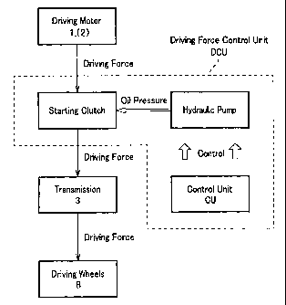
Fig.l is a block diagram showing a drive system of a vehicle
on which a driving force control unit according to one embodiment
s of the invention is mounted;
Fig.2 is a flow chart showing a basic control example of
the driving force control unit;
Fig.3 exemplifies relations between vehicle speed and
driving force value regarding the driving force control unit.
Fig.4 shows a flow chart when driving force is switched to
the smaller condition in the vicinity of a certain vehicle speed;
Fig.5 shows a system configuration of a vehicle provided
with a driving force control unit according to one example of the
invention;
~s Fig.6 shows a configuration of a braking force control unit
according to one example of the invention;
Fig.7 shows the control logic of the braking force control
unit of Fig.6, in which Fi'g.7A shows the logic for retaining
braking force, and Fig.?B shows the logic for permitting
20 operations of the braking force control unit;
Fig.8 shows the controls of the driving force control unit,
in which Fig.8A shows the control logic for switching to a weak
creep condition, Fig.8B shows the control logic for switching to
a strong creep condition for driving, and Fig _ 8C shows the control
2s logic for switching to a middle creep condition, respectively;
_ g _
CA 02313724 2000-07-07
Fig.9 is the control logic for automatically stopping an
engine of a driving motor stopping unit according to one example
of the invention;
Fig.lO shows the controls of the braking force control unit,
s in which Fig.lOA shows the control logic for releasing retained
braking force, and Fig.lOB shows the control logic for judging
a creep rising condition, respectively;
Fig. 11 shows the controls of the driving force control unit,
in which Fig.llA and 11B show the control logic for switching to
the strong creep condition. Here, Fig.llA shows a backward
displacement detecting version, and Fig.llB shows a vehicle
movement detecting version, respectively;
Fig. l2 shows the controls of the driving motor stopping
unit, in which Figs.l2A and 12B show the control loc for
automatically actuating the engine. Here, Fig.l2A shows a
backward displacement detecting version, and Fig.l2B shows a
vehicle movement detecting version, respectively;
Fig.l3 shows a way of detecting backward displacement of
the vehicle, in which Fig.l3A shows a construction thereof,
Fig.l3B shows a pulse phase for ~1 direction of Fig.l3A, and
Fig.l3C shows a pulse phase for ~ direction of Fig.l3A,
respectively;
Fig.l4 is a time chart of a vehicle provided with a driving
force control unit according to the invention, while the vehicle
25 is running, in which Fig.14A shows relations between elapsed time
- 10 -
CA 02313724 2000-07-07
during idling running and vehicle speed, Fig.l4B shows relations
between elapsed time during idling running and the number of
engine speed, Fig.14C shows relations between elapsed time during
idling running and speed ratio of the starting clutch, and Fig.14D
shows relations between elapsed time during idling running and
driving force value, respectively;
Fig.15 is a time chart of a vehicle provided with a driving
force control unit according to the invention, while the vehicle
is running, in which Fig.lSA shows a change of vehicle speed when
the brake pedal is depressed at a vehicle speed less than the
vicinity of a certain vehicle speed during idling running, and
Fig.15B shows a change of driving force value when the brake pedal
is depressed at a vehicle speed less than the vicinity of a certain
vehicle speed during idling running; and
Fig.l6 is a time chart of a vehicle provided with a driving
force control unit according to the invention, while the vehicle
is running, in which Fig.l6A shows a change of vehicle speed when
the brake pedal is depressed in the vicinity of a certain vehicle
speed during idling running, and Fig.16B shows a change of driving
force value when the brake pedal is depressed in the vicinity of
a certain vehicle speed during idling running.
A driving force control unit according to the present
- 11 -
CA 02313724 2000-07-07
invention will be described with reference to the drawings.
<Driving Force Control Unit>
[Configuration of Driving Force Control Unit]
As shown in Fig.l, a driving force control unit DCU
comprises a starting clutch and the like. In response to a control
signal from a control unit CU, the driving force control unit DCU
transmits driving force (creep force) generated at a driving motor
1 while idling to driving wheels 8 through a transmission 3 with
the driving force set in a greater condition (strong creep
condition) or a smaller condition (weak creep condition). A
clutch as the starting clutch may be disposed on the input side
of the transmission 3.
Combination of the driving force control unit DCU and the
transmission 3 is exemplified by (1) the combination of the
starting clutch as an essential part of the driving force control
unit DCU and a belt-type continuously variable transmission
(hereinafter referred to as CVT) as the transmission 3, (2) the
combination of a fluid type torque converter as an essential part
of the driving force control unit DCU and an power transfer as
the transmission 3, and the like. Specifically, in the latter
combination ( 2 ) , the driving force control unit DCU comprises a
fluid type torque converter and a hydraulically engaging element
such as a hydraulic clutch (hydraulic brake) furnished to the
power transfer.
2s In the combination (1), in order to create a greater
- 12 -
CA 02313724 2000-07-07
condition and a smaller condition of driving force, the starting
clutch ( hydraulic multiple disc clutch ) as an essential part of
the driving force control unit DCU is supplied with pressure oil
at a certain oil pressure value from a hydraulic pump, based on
a control signal (hydraulic pressure command value) transmitted
by the control unit CU. For example, the hydraulic pressure
command value is transmitted to a linear solenoid valve for
controlling the oil pressure value of the starting clutch.
When the oil pressure value from the hydraulic pump to the
,o starting clutch is reduced, the pressing force of the clutch plate
(engaging force) is lowered and a smaller driving force condition
is achieved. Meanwhile, when the oil pressure value is increased,
the pressing force of the clutch plate rises and a greater driving
force condition is achieved.
In the combination (2), in order to create a greater
condition and a smaller condition of driving force, the hydraulic
clutch and the like furnished to the power transfer as an essential
part of the driving force control unit DCU are supplied with
pressure oil at a certain oil pressure value from the hydraulic
pump, based on a hydraulic pressure command value transmitted by
the control unit CU. The greater condition and the small
condition are thus created.
Judgement is carried out whether or not the driving force
in each condition takes a proper value. This can be carried out
25 based on the speed ratio by the input and output sides of the
- 13 -
CA 02313724 2000-07-07
starting clutch (the hydraulic clutch furnished to the power
transfer, in the case of the combination ( 2 ) ) . When the driving
force is judged to be greater than the proper value, the hydraulic
pressure value from the hydraulic pump to the starting clutch may
s be lowered so that the driving force can be controlled to a proper
magnitude.
Switching of the driving force is carried out in
consideration of the vehicle speed, depression and release of the
accelerator pedal, depression and release of the brake pedal, and
the range position of the transmission. To this end, the vehicle
is provided at least with means for detecting vehicle conditions,
such as a vehicle speed meter for detecting vehicle speed,
throttle switch for detecting conditions of accelerator pedal
depression, brake switch for detecting conditions of brake pedal
depression, and a positioning switch for detecting range position
of the transmission.
According to the invention, the driving force value in the
greater driving force condition is changed according to the
vehicle speed. In the case of the combination ( 1 ) , such control
for changing the driving force value is achieved, for example by
the following processes and with the provision of a table in the
control unit CU showing relations between vehicle speed and oil
pressure value supplied to the starting clutch. The vehicle speed
detected by the vehicle speed meter is inputted into the control
is unit CU. Subsequently, based on the table, the control unit CU
- 14 -
CA 02313724 2000-07-07
inputs a hydraulic pressure command value corresponding to the
vehicle speed into a linear solenoid valve. Then, pressure oil
is supplied to the starting clutch based on this hydraulic
pressure command value. The control unit CU outputs a hydraulic
pressure command value by the input of a vehicle speed.
Meanwhile, in the case of the combination ( 2 ) , the control
for changing the driving force value in the greater condition in
accordance with the vehicle speed is achieved without external
control, because of the own characteristic of the fluid type
torque converter. The vehicle speed-driving force value
characteristic of the fluid type torque converter in the greater
driving force condition takes the maximum when the vehicle speed
is 0 km/h.
(Basic Control of Driving Force Control Unit while Running]
Basic control for the driving force control unit DCU while
running will be described.
The driving force control unit DCU allows transmission of
driving force from the driving motor to the driving wheels
irrespective of releasing the accelerator pedal at a certain or
lower vehicle speed when the transmission is selected to a running
range, and it switches the magnitude of the driving force to a
smaller condition if the brake pedal is depressed and to a greater
condition if the brake pedal is released. From a signal of the
brake switch, the control unit CU detects whether the brake pedal
25 is depressed or not.
- 15 -
CA 02313724 2000-07-07
The reason for switching the driving force to the smaller
condition when depressing the brake pedal BP is for facilitating
stops of the vehicle as well as for preventing vibrations during
the vehicle stops, by way of reducing the driving force (creep
force) unnecessary for stopping the vehicle. Meanwhile, the
reason for switching the driving force to the greater condition
while releasing the brake pedal BP is for preparation of a starting
operation or acceleration of the vehicle as well as for resisting
a gentle slope without braking force. Switching of the driving
io force to the smaller condition is carried out for the purpose of
reducing loads to the engine 1 and improved fuel consumption by
way of reducing loads to the hydraulic pump of the starting clutch.
In this preferred embodiment, when the accelerator pedal
is depressed and the transmission selects a running range, the
driving force control unit DCU increases the pressing force of
the clutch plate at the starting clutch irrespective of the
condition whether the brake pedal is depressed or not. The
driving force is therefore increased to the greater condition or
more. In this case, sliding of the clutch plate at the starting
zo clutch is none or little.
With reference to a flow chart of Fig.2, basic control of
the driving force control unit DCU while the vehicle is running
will be described. As shown in Fig.2, a running range of the
transmission is detected and judged (J1) so that driving force
is is not transmitted to the driving wheels 8 ( driving force is zero )
- 16 -
CA 02313724 2000-07-07
unless in a running range. If the transmission selects a running
range, depression of the accelerator pedal is detected and judged
( J2 ) . When the accelerator pedal is depressed, driving force is
switched to the greater condition. When the accelerator pedal
is not depressed, the vehicle speed is detected and judged ( J3 ) .
Driving force is then switched to the greater condition or more
if the vehicle speed is over a certain vehicle speed. If the
vehicle speed is at the certain or lower vehicle speed, depression
of the brake pedal BP is detected and judged ( J4 ) . Driving force
is switched to the greater condition unless the brake pedal BP
is depressed. Meanwhile, driving force is switched to the smaller
condition if the brake pedal BP is depressed.
[Control of Driving Force value in Greater Driving Force
Condition]
The driving force control unit DCU changes the driving force
value in the greater driving force condition according to the
vehicle speed. As best seen in Fig.3, the driving force control
unit DCU controls the driving force value so as to present a
characteristic in that the driving force value becomes smaller
as reaching from the vehicle speed at the maximum driving force
value to the certain vehicle speed. For example, the vehicle
speed at the maximum driving force value is 0 km/h, and the certain
vehicle speed is 5 km/h. In this figure, the driving force value
decreases rectilinearly in accordance with the vehicle speed.
25 However, it may decrease to draw a curving figure. In the case
- 17 -
CA 02313724 2000-07-07
of the aforementioned combination ( 1 ) , i. e. , the vehicle provided
with an automatic transmission in combination of CVT as the
transmission 3 and the starting clutch, control is made on the
hydraulic pressure value of the starting clutch so as to obtain
the characteristic in that the driving force value decreases in
accordance with the vehicle speed. Meanwhile, in the case of the
aforementioned combination (2), i.e., the vehicle with a fluid
type torque converter, such a fluid type torque converter is free
from external control and originally has own characteristic in
that the driving force value decreases in accordance with the
vehicle speed.
The relations between vehicle speed and driving force value
( Fig. 3 ) correspond to the table provided at the control unit CU.
[Switching to Smaller Driving Force Condition]
The driving force control unit DCU switches driving force
from the greater condition to the smaller condition if the brake
pedal is depressed while the driving force is in the greater
condition. The switching of the driving force from the greater
condition to the smaller condition is permitted merely in the
vicinity of a certain vehicle speed at a certain or lower vehicle
speed. Such a restriction is required in order to prevent
unintentional strong deceleration of the vehicle. This is
because if switching to the smaller condition is permitted while
greater driving force difference (difference of the driving force
25 values) exists between the greater driving force condition and
- 18 -
CA 02313724 2000-07-07
the smaller driving force condition, driving force suddenly
decreases with the driver' s brake pedal operation. As a result,
the driver receives unintentional strong deceleration, which is
greater than the amount of the brake pedal depression. The
restriction is also required in order to prevent a momentary
backward displacement of the vehicle.
Here, the "vicinity of a certain vehicle speed" where.
switching of the driving force is carried out indicates a vehicle
speed range from the certain vehicle speed (5 km/h) to the vehicle
speed approximately a half extent of the maximum driving force
value, and "a certain vehicle speed" itself is also included in
its vehicle speed range. Difference between the driving force
values in the greater driving force condition and the smaller
driving force condition is small in this vehicle speed range.
Therefore, the driver does not receive any unintentional strong
deceleration even if the driving force is switched to the smaller
condition upon depressing the brake pedal.
Switching of the driving force includes the following three
cases : ( 1 ) switching is permitted merely in a particular vehicle
speed range within the vicinity of the certain vehicle speed; ( 2 )
switching is permitted merely at a particular vehicle speed within
the vicinity of the certain vehicle speed; and ( 3 ) switching is
permitted in all the vehicle speed range within the vicinity of
the certain vehicle speed.
25 With reference to Fig.4, control of the driving force
- 19 -
CA 02313724 2000-07-07
control unit DCU when switching the driving force in the vicinity
of the certain vehicle speed will be described. Here, the driving
force is in the greater condition, the transmission is selected
to a running range, and the accelerator pedal is released.
As shown in Fig.4, depression of the brake pedal is detected
(S1) and judged (S2). The greater condition is retained unless
the brake pedal is depressed ( S3 ) . On the contrary, if the brake
pedal is depressed, the vehicle speed is detected (S4).
Subsequently, judgement is carried out as to whether or not the
,o vehicle speed is in the vicinity of the certain vehicle speed ( S5 ) .
Unless in the vicinity of the certain vehicle speed, the greater
condition is retained (S4) so that the driver does not receive
any unintentional strong deceleration. If the vehicle speed is
in the vicinity of the certain vehicle speed, the driving force
is switched to the smaller condition ( S6 ) . Since difference of
the driving force values between the greater condition and the
smaller condition is small, the driver does not receive any
unintentional strong deceleration even if the driving force is
switched to the smaller condition.
Specifically, the driving force control unit DCU actuates
so as to decrease the driving force from the greater condition
to the smaller condition under the following two circumstances .
Here, the transmission is selected to a running range, and the
accelerator pedal is released.
25 For example, (1) when the vehicle climbs up a slope by
- 20
CA 02313724 2000-07-07
inertia and the vehicle speed gradually decreases without
operating the brake pedal, the driving force is switched to the
greater condition at a certain vehicle speed ( 5 km/h ) . When the
driver depresses the brake pedal while the vehicle speed further
decreases gradually and the vehicle speed is in the vicinity of
the certain vehicle speed, the driving force is decreased to the
smaller condition by the depression of the brake pedal. Unless
in the vicinity of the certain vehicle speed, the driving force
is kept in the greater condition.
For example, ( 2 ) in order to start the vehicle by the driving
force in the greater condition, depression of the brake pedal is
released while the vehicle stops with the brake pedal depressed,
and the driving force is changed to the greater condition. If
the brake pedal is depressed before the vehicle speed increases
over the certain vehicle speed, the driving force decreases to
the smaller condition on condition that the vehicle speed at the
depression of the brake pedal is in the vicinity of the certain
vehicle speed. The driving force in the greater condition is kept
unless the vehicle speed is in the vicinity of the certain vehicle
speed.
In both cases ( 1 ) and ( 2 ) , the driving force control unit
DCU switches the driving force to the smaller condition on
condition that the difference of the driving force between the
greater condition and the smaller condition is smaller (in the
25 vicinity of the certain vehicle speed). Since braking force
- 21 -
CA 02313724 2000-07-07
resulting from the reduced driving force is smaller, the driver
does not receive unintentional strong deceleration even if the
driving force is switched to the smaller condition by the driver' s
brake pedal operation.
If the difference of the driving force between the greater
condition and the smaller condition is greater (not in the
vicinity of the certain vehicle speed), the driver receives
unintentionalstrong deceleration by decreasing the driving force
since braking force resulting from the reduced driving force
affects the vehicle. Moreover, in an up slope, since the driving
force against the slope decreases instantly, the vehicle often
and momentarily displaces backwards. For this reason, reduction
of the driving force is not carried out unless the vehicle speed
is in the vicinity of the certain vehicle speed.
[Examples]
The present invention will be described in greater detail
in connection with the following examples . However, it would be
understood that the present invention is not limited by such
specific examples.
zo <System Configuration of Vehicle and Others>
The system configuration of a vehicle on which is mounted
a driving force control unit according to the present invention
( hereinafter referred to as a "vehicle" ) will be described with
reference to Fig.S. The vehicle is a hybrid type vehicle having
is an engine 1 and an electric motor 2 as a driving motor, and is
provided with CVT 3 as a transmission. The engine 1 is an internal
- 22 -
CA 02313724 2000-07-07
combustion engine operable by gasoline and the like, and the
electric motor 2 is operable by electricity.
[Engine (Driving Motor), CVT (Transmission) and Motor (Driving
Motor)]
s The engine 1 is controlled at a fuel injection electronic
control unit ( hereinafter referred to as FI ECU ) . The FI ECU is
integrally constructed with a management electronic control unit
(hereinafter referred to as MG ECU), and it is incorporated in
a fuel injection/management electronic control unit 4
~o (hereinafter referred to as FI/MG ECU) . The motor 2 is controlled
at a motor electronic control unit 5 ( hereinafter referred to as
MOT ECU ) . Further, the CVT 3 is controlled at a CVT electronic
control unit 6 (hereinafter referred to as CVT ECU).
A drive axle 7 provided with driving wheels 8, 8 is mounted
~s to the CVT 3. Each driving wheel 8 is provided with a disc brake
9, which includes a wheel cylinder WC and the like ( Fig. 6 ) . The
wheel cylinders WC of the disc brakes 9, 9 are connected to a master
cylinder MC through a braking force control unit BCU. When the
driver depresses the brake pedal BP, brake pedal load generated
zo is transmitted to the master cylinder MC through the master power
MP. The brake switch BSW detects whether the brake pedal BP is
depressed or not.
The engine 1 is an internal combustion engine, which makes
use of thermal energy. The engine 1 drives the driving wheels
2s 8, 8 through the CVT 3 and the drive axle 7. In order to improve
fuel consumption, the engine 1 may be automatically stopped while
- 23 -
CA 02313724 2000-07-07
the vehicle stops . For this reason, the vehicle is provided with
a driving motor stopping unit for automatically stopping the
engine 1 when a certain automatic engine stop condition is
satisfied.
s The motor 2 has an assist mode for the assist of the engine
drive with the use of electric energy from a non-shown battery.
The motor 2 has a regeneration mode for converting the kinetic
energy derived from the rotation of the drive axle 7 into electric
energy. when the engine does not require the assist from the
~o assist mode ( such as for starting on a down slope or deceleration
of the vehicle), the thus converted electric energy is stored in
a non-shown battery. Further, the motor 2 has an actuation mode
for actuating the engine 1.
The CVT 3 includes an endless belt winded between a drive
~s pulley and a driven pulley so as to enable continuously variable
gear ratio by changing a winding radius of the endless belt.
Change of the winding radius is achieved by changing each pulley
width. The CVT 3 engages a starting clutch and an output shaft
so as to transmit the output of the engine 1 converted by the
zo endless belt into the drive axle 7 through gears at the output
side of the starting clutch. The vehicle equipped with the CVT
3 enables creep running while the engine 1 is idling, and such
a vehicle requires a driving force control unit DCU for decreasing
driving force to be utilized for the creep running.
2s (Driving Force Control Unit]
The driving force control unit DCU is incorporated in the
- 24 -
CA 02313724 2000-07-07
CVT 3. The driving force control unit DCU variably controls the
driving force transmission capacity of the starting clutch,
thereby changing creep force. The driving force control unit DCU
comprises the starting clutch furnished to the CVT 3 and CVT ECU
s 6 to be described later.
The driving force control unit DCU controls the driving force
transmission capacity of the starting clutch and switches to the
predetermined driving force in each creep condition when the CVT
ECU 6 judges conditions (hereinafter described) required for a
~o weak creep condition, middle creep condition, strong creep
condition or a strong creep condition for driving. Switching of
the driving force transmission capacity may be carried out while
the vehicle stops. The driving force control unit DCU changes
the driving force value in the strong creep condition according
is to the vehicle speed. As shown in Fig.l4, the driving force value
in the strong creep condition becomes the maximum at the vehicle
speed of 0 km/h (when the vehicle stops ) and the minimum in the
vicinity of the certain vehicle speed (5 km/h). Further, the
driving force control unit DCU increases the driving force
2o transmission capacity of the starting clutch and switches to the
strong creep condition if a movement or backward displacement of
the vehicle is detected upon starting the vehicle on a slope. The
CVT ECU 6 judges conditions for switching the creep force, and
it transmits a hydraulic pressure command value to a linear
is solenoid valve of the CVT 3, where the engagement hydraulic
pressure of the starting clutch is controlled. In the driving
_ 25 _
CA 02313724 2000-07-07
force control unit DCU, the engagement force of the starting
clutch is adjusted at the CVT 3 based on the hydraulic pressure
command value. The driving force transmission capacity is
therefore changed and the creep force is adjusted. Since the
s driving force control unit DCU decreases the driving force,
improved fuel consumption of the vehicle is achieved. Fuel
consumption of the vehicle is improved by the reduction of loads
at the engine 1, a hydraulic pump of the starting clutch and the
like. The term "driving force transmission capacity" indicates
~o the maximum driving force (driving torque) transmitted by the
starting clutch. Therefore, if the driving force generated at
the engine 1 is greater than the driving force transmission
capacity, the starting clutch does not transmit the remaining
driving force, which is beyond the driving force transmission
1s capacity, to driving wheels 8, 8....
When a failure-detecting unit DU detects malfunction of the
braking force control unit BCU, operations of the driving force
control unit DCU is restricted.
According to this embodiment, creep force of the vehicle
zo includes three conditions, i.e., a strong condition, weak
condition, and a middle condition between the strong and weak
conditions. The driving force transmission capacity at each
condition is predetermined so as to be greater in the strong
condition, less in the weak condition, and intermediate in the
2s middle condition.
In this embodiment, the strong condition (strong creep
- 26 -
CA 02313724 2000-07-07
force) is referred to as a strong creep condition, and the weak
condition (weak creep force) is referred to as a weak creep
condition, and further the middle condition (intermediate creep
force) is referred to as a middle creep condition. Further, the
s strong creep condition includes a strong creep condition at a
vehicle speed of 5 km/h or lower and a strong creep condition over
the vehicle speed of 5 km/h. The former (strong creep condition
at a vehicle speed of 5 km/h or lower) is merely referred to as
a strong creep condition, and the latter ( strong creep condition
~o over the vehicle speed of 5 km/h) is referred to as a strong creep
condition for driving.
In the strong creep condition, driving force is adjusted
so as to keep the vehicle stationary on a slope having an
inclination angle of 5 degrees. However, in the strong creep
~s condition, the driving force value is decreased according to the
vehicle speed (Fig.l4A and Fig.l4B). The strong creep condition
is achieved when the accelerator pedal is released at a certain
or lower vehicle speed (idling condition) and the positioning
switch PSW selects a running range and further the brake pedal
zo BP is released. The wording "the positioning switch PSW selects
a running range" means that the transmission is selected to a
running range.
In the strong creep condition for driving, driving force
is adjusted to be less than that in the strong creep condition
2s (Fig.l4D). The strong creep condition for driving is a
preliminary condition before switching to the weak creep
- 27 -
CA 02313724 2000-07-07
condition. The strong creep condition for driving is not included
in the greater condition of the claims.
In the middle creep condition, driving force is controlled
substantially to a half extent between the strong creep condition
s and the weak creep condition. The middle creep condition is an
intermediate condition when driving force is stepwise decreased
in the process of switching from the strong creep condition to
the weak creep condition.
In the weak creep condition, almost no driving force is
obtained. The weak creep condition is achieved when the brake
pedal BP is depressed. In the weak creep condition, the vehicle
stops or moves at an extremely low speed.
[Positioning Switch)
Range positions of the positioning switch PSW are selected
by a shift lever. Such range positions are selected from P range
to be used for parking the vehicle, N range as a neutral range,
R range for backward running, D range to be used for a normal run,
and L range to be used for obtaining a sudden acceleration or strong
engine brake. The term "running range" indicates a range position,
zo at which the vehicle can move. In this vehicle, the running range
includes D range, L range and R range. Further, when the
positioning switch PSW selects D range, D mode as a normal running
mode and S mode as a sports mode can be selected by a mode switch
MSW. Information of the positioning switch PSW and the mode
is switch MSW is transmitted to the CVT ECU 6 and further to a meter
10. The meter 10 indicates the range information and the mode
- 28 -
CA 02313724 2000-07-07
information selected by the positioning switch PSW and the mode
switch, respectively.
In this embodiment, reduction of the creep force ( switching
operation to the middle creep condition and the weak creep
s condition ) is carried out while the positioning switch PSW is in
D range or L range. The strong creep condition is retained while
the positioning switch PSW is in R range. Driving force is not
transmitted to the driving wheels 8, 8 while the positioning
switch PSW is in N range or P range. However, the driving force
~o transmission capacity is decreased and the driving force is
substantially switched to the weak creep condition. This will
be described later in greater detail.
[ECU and Others]
FI ECU contained in the FI/MG ECU 4 controls the amount of
~s fuel injection so as to achieve the optimum air fuel ratio, and
it also generally controls the engine 1. Various kinds of
information such as a throttle angle and conditions of the engine
1 is transmitted to the FI ECU such that the engine 1 is controlled
based on such information. The MG ECU contained in the FI/MG ECU
20 4 mainly controls the MOT ECU 5 as well as judges automatic engine
stop conditions and automatic engine actuation conditions. The
MG ECU receives information as to conditions of the motor 2 and
other information such as conditions of the engine 1 from the FI
ECU, and based on such information it sends instructions about
is mode switching of the motor 2 to the MOT ECU 5. Further, the MG
ECU receives information such as conditions of the CVT 3,
- 29 -
CA 02313724 2000-07-07
conditions of the engine 1, range information of the positioning
switch PSW, conditions of the motor 2 and the like, and based on
such information it judges whether the engine 1 should be
automatically stopped or automatically actuated.
s The MOT ECU 5 controls the motor 2 based on a control signal
from the FI/MG ECU 4. The control signal from the FI/MG ECU 4
includes mode information instructing actuation of the engine 1
by the motor 2, assistance of the engine actuation or regeneration
of electric energy, and an output required value to the motor 2 ,
and the MOT ECU 5 sends an order to the motor 2 based on such
information. Further, the. MOT ECU 5 receives information from
the motor 2 and transmits information such as the amount of
generated energy and the capacity of the battery to the FI/MG ECU
4.
~s The CVT ECU 6 controls the transmission gear ratio of the
CVT 3, the driving force transmission capacity of the starting
clutch and the like. Various kinds of information such as
conditions of the CVT 3, conditions of the engine 1, range
information of the positioning switch PSW and the like is
zo transmitted to the CVT ECU 6, and based on such information the
CVT ECU 6 transmits a signal to the CVT 3, the signal of which
includes control of hydraulic pressure of each cylinder provided
at the drive pulley and the driven pulley of the CVT 3, and control
of hydraulic pressure of the starting clutch. As shown in~Fig.6,
is the CVT ECU 6 comprises a control unit CU for the ON/OFF control
( shut-of f /communicate ) of the solenoid valves SV ( A ) , SV ( B ) which
- 30 -
CA 02313724 2000-07-07
function as braking force retaining means RU of the braking force
control unit BCU. The CVT ECU 6 transmits a signal for ON and
OFF the solenoid valves SV (A) , SV ( B ) to the braking force control
unit BCU. Further, the CVT ECU 6 judges switching of the creep
s force as well as judges whether the driving force should be
increased as a result of detecting a movement (or a backward
displacement ) of the vehicle while the braking force control unit
BCU actuates. Information of such judgement is transmitted to
the driving force control unit DCU of the CVT 3. The CVT ECU 6
~o comprises a failure-detecting unit DU for the purpose of detecting
malfunction of the braking force control unit BCU.
The CVT ECU 6 judges switching of the creep force as well
as judges the increment of the driving force upon detecting a
movement (or backward displacement) of the vehicle, and based on
~s the judgement, it transmits a hydraulic pressure command value
to a linear solenoid valve controlling the engagement hydraulic
pressure of the starting clutch.
[Brake (Braking force control unit)]
The disk brakes 9, 9 are constructed such that a disk rotor
zo rotatable with the driving wheel 8 is pressed between the brake
pads moved by the wheel cylinder WC ( Fig. 5 ) and braking force is
obtained by the frictional force therebetween. Brake fluid
pressure within the master cylinder MC is transmitted to the wheel
cylinders WC through the braking force control unit BCU.
2s The braking force control unit BCU continuously retains
brake fluid pressure within a wheel cylinder WC, i.e. braking
- 31 -
CA 02313724 2000-07-07
force after depression of the brake pedal BP is released. The
braking force control unit BCU comprises a control unit CU within
the CVT ECU 6. Construction of the braking force control unit
BCU will be described later in greater detail with reference to
s Fig.6.
ON/OFF operation of the solenoid valve is meant as follows
In the normally open type solenoid valve, when the solenoid valve
is ON, the solenoid valve closes to a shut-off position where a
flow of brake fluid is shut off, and when the solenoid valve is
OFF, the solenoid valve opens to a communicating position where
a flow of brake fluid is allowed. Meanwhile, in the normally
closed type solenoid valve, when the solenoid valve is ON, the
solenoid valve opens to a communicating position where a flow of
brake fluid is allowed, and when the solenoid valve is OFF, the
~s solenoid valve closes to a shut-off position where a flow of brake
fluid is shut off. As will be described later, solenoid valves
SV ( A ) , SV ( B ) in this example are of normally open type . A driving
circuit within the control unit CU carries out or ceases a supply
of electric currents to respective coils of the solenoid valves
zo SV(A), SV(B) so as to ON and OFF the solenoid valves.
A master cylinder MC is a device for converting the brake
pedal depression into hydraulic pressure. In order to assist the
brake pedal depression, a master power MP is provided between the
master cylinder MC and the brake pedal BP. The master power MP
is enhances braking force by way of applying negative pressure of
the engine 1 or compressed air to the driver's brake pedal
- 32 -
CA 02313724 2000-07-07
depression force. A brake switch BSW is provided at the brake
pedal BP so as to detect whether or not the brake pedal BP is
depressed.
[Driving Motor Stopping Unit]
s The driving motor stopping unit incorporated in the vehicle
is constructed by the FI/MG ECU and others. The driving motor
stopping unit enables an automatic engine stop operation while
the vehicle stops. The automatic engine stop conditions are
judged at the FI/MG ECU 4 and the CVT ECU 6. The automatic engine
~o stop conditions will be described later. When all of the
automatic engine stop conditions are satisfied, the FI/MG ECU 4
sends an engine stop order to the engine 1 so as to automatically
stop the engine 1. Since the driving motor stopping unit
automatically stops the engine 1, improved fuel consumption of
~s the vehicle is achieved.
The FI/MG ECU 4 and the CVT ECU 6 judges automatic engine
actuation conditions while the driving motor stopping unit
automatically stopping the engine 1. When all of the automatic
engine actuation conditions are satisfied, the FI/MG ECU 4 sends
zo an engine actuation order to the MOT ECU 5. The MOT ECU 5 further
transmits an engine actuation order to the motor 2. The motor
2 then automatically actuates the engine 1, and at the same time
driving force is switched to the strong creep condition. The
automatic engine actuation conditions will be described later.
2s Further, when the failure-detecting unit DU detects
malfunction of the braking force control unit BCU, operation of
- 33 -
CA 02313724 2000-07-07
the driving motor stopping unit is prohibited.
[Signals]
Signals to be transmitted and received in this system will
be described. With reference to Fig.S, the letter "F-" in front
s of each signal indicates that the signal is flag information,
which is either 0 or 1 . The letter "V-" indicates that the signal
is numerical information ( unit is optional ) , and the letter "I_"
indicates that the signal includes plural kinds of information.
A signal transmitted from the FI/MG ECU 4 to the CVT ECU 6
io will be described. V MOTTRQ represents an output torque value
of the motor 2 . F MGSTB is a flag showing whether all of the engine
stop conditions judged at the FI/MG ECU 4 are satisfied. If all
the conditions are satisfied, the numeral 1 is given, and if not,
the numeral 0 is given. The automatic engine stop conditions
~s regarding F MGSTB will be described later. When F MGSTB and
F CVTOK ( hereinafter described ) are both turned to 1, the engine
1 is automatically stopped. When one of these flags is turned
to 0, the engine 1 is automatically actuated.
A signal transmitted from the FI/MG ECU 4 to the CVT ECU 6
zo and the MOT ECU 5 will be described. V NEP represents engine
speed.
A signal transmitted from the CVT ECU 6 to the FI/MG ECU 4
will be described. F MCRPON is a flag whether or not driving force
is in the middle creep condition. The numeral 1 is given in the
2s middle creep condition, and if not, the numeral 0 is given. When
F MCRPON is 1, the engine 1 is required to blow middle air in the
- 34 -
CA 02313724 2000-07-07
middle creep condition (weaker air than that in the strong creep
condition) . F AIRSCRP is a strong air demand flag in the strong
creep condition. If strong air is required in the strong creep
condition, the numeral 1 is given, and if not, the numeral 0 is
s given . When both F MCRPON and F AIRSCRP are 0 , FI /MG ECU 4 blows
weak air in the weak creep condition. In order to keep the engine
idle speed at a certain level regardless of the driving force in
the strong creep condition, middle creep condition or the weak
creep condition, output of the engine should be adjusted by way
io of blowing corresponding air to the strong creep condition, middle
creep condition or the weak creep condition. When driving force
is in the strong creep condition and a load of the engine 1 is
higher, a strong air blow (strong air in the strong creep
condition) is required. The term "air blow" means the supply of
~s air from an air passage by-passing a throttle valve of the engine
1 to an intake pipe positioned at a downstream of the throttle
valve. Air is adjusted by controlling degrees of opening of the
air passage.
F CVTOK is a flag showing whether all of the engine stop
2o conditions judged at the CVT ECU 6 are satisfied. If all the
conditions are satisfied, the numeral 1 is given, and if not, the
numeral 0 is given. The automatic engine stop conditions
regarding F CVTOK will be described later. F CVTTO is a flag
showing whether the oil temperature of the CVT 3 is over a certain
is value. If the oil temperature is at the certain value or more,
the numeral 1 is given, and if the oil temperature is below the
- 35 -
CA 02313724 2000-07-07
value, the numeral 0 is given. The oil temperature of the CVT
3 is obtained from an electrical resistance value of the linear
solenoid valve controlling hydraulic pressure of the starting
clutch at the CVT 3. F POSR is a flag showing a condition whether
s the positioning switch PSW is selected in R range. If the
positioning switch PSW selects R range, the numeral 1 is given,
and if not, the numeral 0 is given. F POSDD is a flag showing
a condition whether the positioning switch PSW selects D range
and the mode switch MSW selects D mode. If D range and D mode
( D range/D mode ) are selected, the numeral 1 is given, and if not,
the numeral 0 is given. When the FI/MG ECU 4 does not receive
any information indicating D range/D mode, R range, P range or
N range, the FI/MG ECU 4 judges that either D range/S mode or L
range is selected.
~s A signal transmitted from the engine 1 to the FI/MG ECU 4
and the CVT ECU 6 will be described. V ANP represents a negative
pressure value at the intake pipe of the engine 1. V TH represents
a throttle angle. V TW represents a temperature of the cooling
water at the engine 1. V TA represents the intake temperature
20 of the engine 1. The brake fluid temperature in the braking force
control unit BCU disposed within the engine compartment is
obtained from the intake temperature. This is because both
temperatures change with respect to the temperature at the engine
compartment.
2s A signal transmitted from the CVT 3 to the FI/MG ECU 4 and
the CVT ECU 6 will be described. V VSP1 represents a vehicle speed
- 36 -
CA 02313724 2000-07-07
pulse from one of two vehicle speed pickups provided in the CVT
3 . Vehicle speed is calculated based on this vehicle speed pulse.
A signal transmitted from the CVT 3 to the CVT ECU 6 will
be described. V NDRP represents a pulse showing the number of
s revolutions of the drive pulley provided at the CVT 3. V NDNP
represents a pulse showing the number of revolutions of the driven
pulley provided at the CVT 3. V VSP2 represents a vehicle speed
pulse from the other vehicle speed pickup at the CVT 3. V VSP2
is more accurate than V VSP1, and V VSP2 is used for calculating
~o the amount of clutch slipping at the CVT 3.
A signal transmitted from the MOT ECU 5 to the FI/MG ECU 4
will be described. V QBAT represents a remaining capacity of the
battery. V ACTTRQ represents an output torque value of the motor
2, which is the same as V MOTTRQ. I MOT represents information
~s such as the amount of generated energy of the motor 2 showing
electric loading. The motor 2 generates all the electric power
consumed for the vehicle including the electric power for driving
the motor.
A signal transmitted from the FI/MG ECU 4 to the MOT ECU 5
zo will be described. V CMDPWR represents an output required value
to the motor 2. V ENGTRQ represents an output torque value of
the engine 1. I MG represents information such as an actuation
mode, assist mode and a regeneration mode with respect to the motor
2.
is A signal transmitted from the master power MP to the FI/MG
ECU 4 will be described. V M/PNP represents a negative pressure
- 37 -
CA 02313724 2000-07-07
detected value at a constant pressure chamber of the master power
MP.
A signal transmitted from the positioning switch PSW to the
FI/MG ECU 4 will be described. N or P is transmitted as
s positioning information when the positioning switch PSW selects
either N range or P range.
A signal transmitted from the CVT ECU 6 to the CVT 3 will
be described. V DRHP represents a hydraulic pressure command
value transmitted to the linear solenoid valve, which controls
~o hydraulic pressure within the cylinder of the drive pulley at the
CVT 3. v DNHP represents a hydraulic pressure command value
transmitted to the linear solenoid valve, which controls
hydraulic pressure within the cylinder of the driven pulley at
the CVT 3. The transmission gear ratio of the CVT 3 is changed
~s by V DRHP and V DNHP. V SCHP represents a hydraulic pressure
command value transmitted to the linear solenoid valve, which
controls the hydraulic pressure of the starting clutch at the CVT
3. The engaging force of the starting clutch (driving force
transmission capacity) is changed by V SCHP.
zo A signal transmitted from the CVT ECU 6 to the braking force
control unit BCU will be described. F SOLA is a flag for ON/OFF
( close/open ) the solenoid valve SV ( A) of the braking force control
unit BCU (shown in Fig.6). The numeral 1 is given for closing
(ON) the solenoid valve SV(A), and the numeral 0 is given for
is opening (OFF) the solenoid valve SV(A). F SOLB is a flag for
ON/OFF ( close/open ) the solenoid valve SV ( B ) of the braking force
- 38 -
CA 02313724 2000-07-07
control unit BCU (shown in Fig.6). The numeral 1 is given for
clos ing ( ON ) the solenoid valve SV ( H ) , and the numeral 0 is given
for opening (OFF) the solenoid valve SV(B).
A signal transmitted from the positioning switch PSW to the
s CVT ECU 6 will be described. The positioning switch PSW selects
N range, P range, R range, D range or I. range, and the selected
range is transmitted as positioning information.
A signal transmitted from the mode switch MSW to the CVT ECU
6 will be described. The mode switch MSW selects either D mode
~o (normal running mode) or S mode (sports running mode), and the
selected mode is transmitted as mode information. The mode switch
MSW is a mode selection switch, which works when the positioning
switch PSW is set in D range.
A signal transmitted from the brake switch BSW to the FI/MG
ECU 4 and the CVT ECU 6 will be described. F BKSW is a flag showing
a condition whether the brake pedal BP is depressed (ON) or
released ( OFF ) . I f the brake pedal BP is depressed, the numeral
1 is given, and if the brake pedal is released, the numeral 0 is
given.
2o A signal transmitted from the CVT ECU 6 to the meter 10 will
be described. The positioning switch PSW selects N range, P range,
R range, D range or L range, and the selected range is transmitted
as positioning information. Further, the modeswitch MSW selects
either D mode ( normal running mode ) or S mode ( sports running mode ) ,
2s and the selected mode is transmitted as mode. information.
<Braking Force Control Unit>
- 39 -
CA 02313724 2000-07-07
[Construction of Braking Force Control Unit]
The braking force control unit BCU comprises braking force
retaining means RU which is capable of retaining braking force
after releasing the brake pedal BP. The braking force retaining
s means RU continuously retains braking force after releasing the
brake pedal BP, and it releases the braking force after releasing
the brake pedal BP and in the process of increasing driving force
of the vehicle to the strong condition.
As shown in Fig.6, the braking force control unit BCU in this
~o example is incorporated within brake fluid passages FP of a
hydraulically operable braking device BK. The braking force
control unit BCU comprises solenoid valves SV as braking force
retaining means RU so as to switch between a communicating
position,where the brake fluid passage FP connecting the master
~s cylinder MC and the wheel cylinders WC is communicated and a
shut-off position where the brake fluid passage FP is shut off
for retaining brake fluid pressure within the wheel cylinders WC.
With reference to Fig.6, the braking force control unit BCU
will be described. The brake fluid pressure circuit BC of the
zo hydraulically operable braking device BK comprises the brake
fluid passage FP connecting the braking device BK to the master
cylinder MC and the wheel cylinders WC. Since brake is a very
important factor for a safety run, the braking device BK has two
separate systems of brake fluid pressure circuits BC ( A ) , BC ( B ) .
is Therefore, if one system is out of order, the remaining system
works for obtaining a minimum braking force.
- 40 -
CA 02313724 2000-07-07
A master cylinder piston MCP is inserted into a main body
of the master cylinder MC. When the driver applies a load to the
brake pedal BP, the piston MCP is pressed and pressure is applied
to brake fluid within the master cylinder MC so that mechanical
s force is converted into brake fluid pressure, i.e., the pressure
applied to the brake fluid. When the driver releases the brake
pedal 'BP for removing the applied load, the piston MCP is returned
to the original position by the resilient action of a return spring
MCS and brake fluid pressure is released. In view of fail-safe
mechanism, there are provided two separate brake fluid pressure
circuits BC. For this reason, the master cylinder MC shown in
Fig.6 is a tandem master cylinder, where two pistons MCP, MCP are
connected in series so that the main body of the master cylinder
MC is divided into two portions.
~s A master power MP (brake booster) is provided between the
brake pedal BP and the master cylinder MC so as to ease the braking
effort of the driver. The master power MP shown in Fig.6 is a
vacuum servo type. The master power MP takes out negative
pressure from an intake manifold of the engine 1 so as to facilitate
zo the braking operation of the driver.
The brake fluid passage FP connects the master cylinder MC
and the wheel cylinders WC. The brake fluid passage FP functions
as a fluid channel for brake fluid. Brake fluid pressure
generated at the master cylinder MC is transmitted to the wheel
is cylinders WC since a flow of the brake fluid travels through the
brake fluid passage FP. When the brake fluid pressure within the
- 41 -
CA 02313724 2000-07-07
wheel cylinders WC is greater, the brake fluid is transmitted from
the wheel cylinders WC to the master cylinder MC through the brake
fluid passage FP. Since separate brake fluid pressure circuits
BC are provided for the reason mentioned above, there are also
s provided two separate brake fluid passage systems FP. The brake
fluid pressure circuit BC such as constructed by the brake fluid
passage shown in Fig.6 is an X-piping type, where one brake fluid
pressure circuit BC(A) is for braking a front right wheel and a
rear left wheel, and the other brake fluid pressure circuit BC(B)
is for braking a front left wheel and a rear right wheel. The
brake fluid pressure circuit may be a front and rear dividing
piping type, where one brake fluid pressure circuit is for braking
front wheels, and the other brake fluid pressure circuit is for
braking rear wheels.
~s The wheel cylinder WC is provided for each wheel 8 so that
brake fluid pressure generated at the master cylinder MC and
transmitted to the wheel cylinders WC through the brake fluid
passage FP is converted into a mechanical force (braking force)
for braking wheels 8 . A piston is inserted into the wheel cylinder
zo WC so that when the piston is pressed by brake fluid pressure,
it generates braking force for actuating brake pads in the case
of disc brakes or brake shoes in the case of drum brakes.
Additionally, there may be provided brake fluid pressure
control valves for controlling brake fluid pressure within the
2s wheel cylinders of the front and rear wheels.
With reference to Fig.6, the braking force control unit BCU
- 42 -
CA 02313724 2000-07-07
will be described. The braking force control unit BCU is
incorporated within the brake fluid passage FP connecting the
master cylinder MC and the wheel cylinders WC and comprises a
solenoid valve SV as braking force retaining means RU. The
s braking force control unit BCU further comprises a restriction
D, check valve CV and a relief valve RV, if necessary.
The solenoid valve SV is actuated by an electric signal from
the control unit CU. The solenoid valve SV shuts off a flow of
brake fluid within the brake fluid passage FP in its shut-off
~o position so as to retain brake fluid pressure applied to the wheel
cylinders WC. A flow of brake fluid within the brake fluid passage
FP is communicated when the solenoid valve SV is in a communicating
position. The two solenoid valves SV(A), SV(B) shown in Fig.6
are both in the communicating position. Provision of the solenoid
is valve SV prevents unintentional backward displacement of the
vehicle upon starting on a slope. This is because when the driver
releases the brake pedal BP, brake fluid pressure is retained
within the wheel cylinder WC. The term "unintentional backward
displacement" means that the vehicle moves in an opposite
zo direction due to its own weight, in other words, the vehicle begins
to descend backwards on a slope.
The solenoid valve SV may be of both normally open and
normally closed types. However, in view of fail-safe mechanism,
a normally open type is preferable. This is because when
2s electricity is cut off due to malfunction, brake does not work
or brake always works in a normally closed type solenoid valve
- 43 -
CA 02313724 2000-07-07
SV. In the normal operation, the solenoid valve SV is shut off
when the vehicle stops, and is kept in the shut-off position until
the vehicle starts to move. Conditions for switching the solenoid
valve SV to the shut-off position or to the communicating position
s will be described later.
A restriction D is provided in case of necessity. The
restriction D always connects the master cylinder MC and the wheel
cylinders WC regardless of the conditions of the solenoid valve
SV such as in the communicating position or the shut-off position.
~o Especially when the solenoid valve SV is in the shut-off position
and the driver gradually or instantly releases the brake pedal
BP, the restriction D reduces brake fluid pressure within the
wheel cylinder WC at a certain speed by gradually transferring
brake fluid from the wheel cylinder WC to the master cylinder MC.
15 Such a restriction D may be formed by the provision of a flow
control valve in the brake fluid passage FP. Alternatively, the
restriction D may be formed at a part of the brake fluid passage
FP by way of a flow resistance ( reduced area portion of the passage,
at which a part of the section becomes narrow).
zo with the provision of the restriction D when the driver
gradually or instantly releases the brake pedal BP, braking force
is gradually lowered so that even if the solenoid valve SV is in
the shut-off position, brake does not work permanently. In other
words, reduction speed of the brake fluid pressure within the
2s wheel cylinder is less than that of brake pedal load applied by
the driver. Therefore, even if the solenoid valve SV is in the
- 44 -
CA 02313724 2000-07-07
shut-off position, braking force is reduced after a certain period
of time so that the vehicle can start to move on an up slope by
the driving force of the driving motor. Meanwhile, the vehicle
can start off on a down slope due to its own weight by merely
s releasing the brake pedal BP gradually or instantly without
requiring the accelerator pedal operation of the driver.
The restriction D does not affect braking force as long as
brake fluid pressure within the master cylinder MC due to the
driver's brake pedal operation is greater than that within the
wheel cylinder WC. This is because brake fluid flows based on
a pressure difference between the wheel cylinder WC and the master
cylinder MC, i.e. from one at higher brake fluid pressure to the
other at lower brake fluid pressure. Unless the driver releases
the brake pedal BP, brake fluid pressure within the wheel cylinder
~s WC does not lower although it may increase. The restriction D
may function as a check valve so as to prevent a counter flow from
the master cylinder MC to the wheel cylinder WC.
Reduction speed of brake fluid pressure within the wheel
cylinder WC is determined so as to prevent the vehicle from
zo unintentional backward displacement during the time the driver
releases the brake pedal BP and driving force is switched from
the weak creep condition to the strong creep condition.
In the case that the reduction speed of brake fluid pressure
within the wheel cylinder WC is faster, the vehicle will displace
2s backwards on the slope before sufficient driving force will be
obtained since braking force after releasing the brake pedal BP
- 45 -
CA 02313724 2000-07-07
will be immediately lost even if the solenoid valve SV is closed.
On the contrary, in the case that the reduction speed of brake
fluid pressure within the wheel cylinder WC is slower, the vehicle
will not displace backwards on the slope after releasing the brake
s pedal BP since brake is working at all times. However, extra time
and driving force is required for obtaining sufficient driving
force against the braking force. As described later, according
to this embodiment, the solenoid valve SV is returned to the
communicating position when driving force is exerted on the
vehicle and depression of the brake pedal BP is released.
Therefore, when the vehicle starts by driving force, reduction
speed of brake fluid pressure within the wheel cylinder WC by way
of the restriction D may be slower.
Reduction speed for reducing brake fluid pressure within the
~s wheel cylinder WC is determined by properties of the brake fluid
or shape of the restriction D (cross section or length of the flow
passage) . The restriction D may be employed as an integral member
with a solenoid valve SV and a check valve CV. In this case, the
number of parts and install space may be reduced.
zo A check valve CV is provided in case of necessity. The check
valve CV transfers brake fluid pressure generated within the
master cylinder MC into the wheel cylinders WC on condition that
the solenoid valve SV is closed and the driver increases brake
pedal load. The check valve CV works effectively when brake fluid
2s pressure generated within the master cylinder MC is greater than
that within the wheel cylinder WC. The check valve CV quickly
- 46 -
CA 02313724 2000-07-07
increases brake fluid pressure within the wheel cylinder WC in
accordance with the increased brake pedal load.
If an arrangement is employed such that the solenoid valve
SV is switched from the shut-off position to the communicating
s position when brake fluid pressure within the master cylinder MC
becomes greater than that within the wheel cylinders WC, there
is no need to provide a check valve CV since the solenoid valve
SV itself responds to the increased brake pedal load.
A relief valve RV is also provided in case of necessity. The
relief valve RV transfers brake fluid within the wheel cylinder
WC into the master cylinder MC until brake fluid pressure within
the wheel cylinder becomes a certain pressure level (relief
pressure) on condition that the solenoid valve SV is in the
shut-off position and the driver gradually or instantly releases
~s the brake pedal BP . The relief valve RV works when brake fluid
pressure within the wheel cylinder WC is greater than the
predetermined brake fluid pressure and brake fluid pressure
within the master cylinder MC. Therefore, even if the solenoid
valve SV is in the shut-off position, extra brake fluid pressure
zo within the wheel cylinder WC beyond the necessary brake fluid
pressure is quickly reduced to the relief pressure. This will
ensure a smooth starting operation of the vehicle even if the
driver forcefully depresses the brake pedal BP more than required.
Provision of the relief valve RV is advantageous when the vehicle
zs starts on a down slope without assistance of driving force, for
example a starting operation of the vehicle due to its own weight
- 47 -
CA 02313724 2000-07-07
by releasing the brake pedal BP.
A brake switch BSW detects whether the brake pedal BP has
been depressed or not. Based on the detected value, the control
unit CU sends instructions as to whether the solenoid valve SV
s should be communicated or shut off.
A servo valve ( linear solenoid valve ) , which can optionally
adjust degrees of valve opening may be employed in place of the
arrangement comprising a relief valve Rv and a check valve CV in
addition to a solenoid valve SV.
[Basic Control of Braking Force Control Unit]
Basic control of the braking force control unit BCU will be
described.
I) Braking force control unit BCU switches the solenoid
valves SV to the communicating position on condition that the
~s brake pedal BP is depressed while the vehicle stops.
( 1 ) Vehicle has to be stopped. This is because the driver
can not park the vehicle at desired positions if the solenoid
valves SV are switched to the shut-off position while the vehicle
is moving at high speeds . However, switching the solenoid valves
2o SV to the shut-off position does not affect the driver's operation
if the vehicle stops. The condition "while the vehicle stops"
includes a condition just before the vehicle stops.
( 2 ) Brake pedal BP is depressed. This is because no braking
force is retained if the brake pedal BP is not depressed. There
is is no significance on switching the solenoid valve SV to the
shut-off position while the brake pedal is released.
- 48 -
CA 02313724 2000-07-07
The driver can stop the vehicle securely on a slope with the
brake pedal BP forcefully depressed if a further condition is
added other than the above conditions (1) and (2). The further
condition requires that the driving force transmission capacity
s is in the smaller condition when the solenoid valves SV are
switched to the shut-off position for retaining braking force.
This leads to improved fuel consumption of the vehicle. The
smaller condition includes a condition of zero driving force and
a condition that the engine 1 stops.
And, II ) Braking force retaining means RU releases braking
force (i.e. the solenoid valves SV are returned to the
communicating position) after releasing the brake pedal BP and
in the process of increasing driving force to the strong
condition.
is ( 1 ) Brake pedal BP is released. This is because the driver
has an intention to start the vehicle when depression of the brake
pedal BP is released.
(2) Driving force is in the process of increasing to the
strong condition (creep rising condition). This is because the
zo driver may experience a sudden start of the vehicle if braking
force is released when the driving force reaches to the strong
condition (strong creep condition). This is more prominent on
a down slope since the vehicle' s own weight additionally affects
driving force of the vehicle per se.
25 However, a smooth starting operation of the vehicle without
a sudden start on a down slope is achieved by the increasing driving
- 49 -
CA 02313724 2000-07-07
force if braking force is released after releasing the brake pedal
BP and in the process of increasing driving force to the strong
condition. There may be a worry that the vehicle displaces
backwards on an up slope if braking force is released in the process
s of increasing driving force to the strong condition. However,
backward displacement of the vehicle on the slope is prevented
by the inertial force and the rolling resistance (increasing
driving force) of the vehicle.
Braking force retained restricts backward displacement of
~o the vehicle until the braking force retention is released after
releasing the brake pedal BP. Thereafter, the inertial force of
the vehicle and the like restrict the backward displacement until
driving force reaches to the strong condition (creep rising
condition). As a result, since driving force increases to the
~s strong condition while backward displacement of the vehicle is
restricted, a smooth starting operation of the vehicle is
achieved.
The process of increasing driving force to the strong
condition includes any point of time after driving force occurs
zo and before the driving force reaches to the strong condition.
However, when few driving force is obtained, release of the
braking force may cause backward displacement of the vehicle on
an up slope, although it is advantageous on a down slope.
Meanwhile, when greater driving force is obtained, release of the
2s braking force may cause a sudden start of the vehicle on a down
slope, although it is advantageous on an up slope. Timing at which
- 50 -
CA 02313724 2000-07-07
release of the braking force is carried out should be determined
in consideration of the inertial force and the rolling resistance
of the vehicle as well as in comparison with advantages and
disadvantages of the slope. This will be described later with
s reference to [Requirement for creep rising condition].
Specific Control of Vehicle
With reference to Figs.7 to 13, control of the vehicle will
be described in greater detail.
<Conditions for Retaining Braking Force>
Conditions for retaining braking force by the braking force
control unit BCU will be described below. As shown in Fig.7A,
braking force is retained when all of the following four
conditions are satisfied.
I) Brake switch BSW is ON.
~s I I ) Running range is other than Neutral ( N range ) , parking
(P range) and Reverse (R range).
III) Operation of the braking force control unit BCU is
permitted.
IV) Vehicle speed is 0 km/h.
2o When all the above conditions are satisfied, both solenoid
valves SV ( A ) , SV ( B ) are switched to the shut-of f pos ition, thereby
retaining braking force.
The above four conditions will be described below.
I ) Brake switch BSW has to be ON, otherwise no braking force
2s or few braking force will be retained within the wheel cylinders
WC.
- 51 -
CA 02313724 2000-07-07
r I ) Running range is other than Neutral ( N range ) , parking
(P range) and Reverse (R range). This is for canceling
unnecessary operation of the braking force control unit BCU in
N range or P range, and in R range, for preventing the vehicle
s from unintentional backward displacement with the aid of the
driving force in the strong creep condition since the strong creep
condition is kept in the Reverse range. Therefore, braking force
is retained while D range ( driving range ) or L range ( low range )
is selected.
~o III) Operation of the braking force control unit BCU is
permitted. This is for reminding the driver of sufficiently
depressing the brake pedal BP before retaining braking force,
thereby preventing unintentional backward displacement of the
vehicle. Since sufficient driving force is obtained in the strong
~s creep condition such that the vehicle can stand still on a slope
at an inclination angle of 5 degrees, the driver often depresses
the brake pedal BP insufficiently. In this circumstance, if the
solenoid valves SV are closed and the engine 1 is stopped, the
vehicle will unintentionally displace backwards. Meanwhile, in
zo the weak creep condition and the middle creep condition, driving
force is not sufficient for stationarily retaining the vehicle
on a slope having an inclination angle of 5 degrees . When driving
force is decreased on a slope, the driver forcefully depresses
the brake pedal BP. This ensures sufficient braking force
2s preventing the vehicle from backward displacement on the slope
even if driving force is decreased or lost. The control logic
- 52 -
CA 02313724 2000-07-07
for permitting an operation of the braking force control unit BCU
will be described later.
IV) Vehicle speed is 0 km/h. This is because the driver can
not select a position for parking the vehicle if the solenoid
s valves SV are switched to the shut-off position during the vehicle
is running.
Meanwhile, since the vehicle stops while the vehicle speed
is 0 km/h, braking force can be retained without any troubles in
the driving operation. "Vehicle speed of 0 km/h" also includes
~o a condition just before the vehicle stops.
[Conditions required for permitting operations of the braking
force control unit]
With reference to Fig.7B,conditionsrequired for permitting
an operation of the braking force control unit BCU will be
~s described. An operation of the braking force control unit BCU
is permitted while driving force is either in the weak creep
condition or in the middle creep condition. In the weak creep
condition and the middle creep condition, driving force is not
sufficient for stationarily retaining the vehicle on a slope
zo having an inclination angle of 5 degrees . For this reason, the
driver is forced to depress the brake pedal BP sufficiently before
retaining braking force so as to obtain sufficient driving force
for preventing backward displacement of the vehicle. Driving
force in the weak creep condition or in the middle creep condition
25 1.S judged based on a hydraulic pressure command value to a linear
solenoid valve of the CVT 3, where the engagement hydraulic
- 53 -
CA 02313724 2000-07-07
pressure of the starting clutch is controlled.
[Conditions required for Weak Creep Order]
Conditions for transmitting a weak creep order will be
described. As shown in Fig.8A, the weak creep order (F WCRP) is
s transmitted when any of the following conditions I) and II) is
satisfied. The conditions are:
I) Transmission is in N range or P range (N range/P range).
II) The following two conditions are both satisfied.
[ ( 1 ) Braking force control unit BCU is normal; ( 2 ) Brake switch
BSW is ON; (3) Advance range (D range/L range) is selected; and
( 4 ) Vehicle speed is at 5 km/h or lower ] and further [ ( 5 ) Vehicle
speed is in the vicinity of a certain vehicle speed; ( 6 ) Driving
force is in the weak creep condition; or ( 7 ) Vehicle speed is 0
km/h, Driving force is in the middle creep condition, and A certain
~s time has passed after switching to the middle creep condition] .
When one of the above conditions I) and II) is satisfied,
the weak creep order is transmitted and driving force is switched
to the weak creep condition.
The above conditions are judged at the driving force control
zo unit DCU. The reason for switching driving force to the weak creep
condition is that vibrations of the vehicle is prevented and fuel
consumption of the vehicle can be improved. In the case of an
up slope, it is for reminding the driver of forcefully depressing
the brake pedal BP so as to prevent backward displacement of the
2s vehicle while the vehicle stops on the slope. In the case of a
flat surface or a down slope, it is for reducing the driving force
- 54 -
CA 02313724 2000-07-07
so that the vehicle can be stopped with smaller braking force.
The conditions for transmitting the weak creep order will
be described.
I) Transmission is in N range or P range. This is because
s if the transmission is selected from a non-driving range (N/P
range) to a driving range (D/L/R range) and at the same time the
accelerator pedal is quickly depressed, the driving force
transmission capacity of the starting clutch can be instantly
increased, allowing a smooth starting operation of the vehicle.
In the weak creep condition, since pressure oil has been filled
in an oil pressure chamber of the starting clutch, there is no
clearance or play for the advance stroke of the piston enforcing
the clutch. Therefore, the driving force transmission capacity
is instantly increased by increasing the pressure value of the
~s pressure oil.
Driving force is switched to the weak creep condition when
the transmission is selected to N or P range. This is for
previously changing the driving force transmission capacity of
the starting clutch to the capacity at the weak creep condition.
zo However, driving force from the engine l.is not transmitted to
the driving wheels 8, 8 . This is distinguished from the weak creep
condition while the transmission is selected to D/L range. In
N/P range, connection between the engine 1 and the driving wheels
8,8 is completely cut by a forward/reverse movement switching
is mechanism arranged in series with the starting clutch on a driving
force transmission path. Since neither a transmission path for
- 55 -
CA 02313724 2000-07-07
the forward movement nor a transmission path for the reverse
movement is provided in N/P range, driving force from the engine
1 is not transmitted to the driving wheels 8, 8.
II) conditions (1) to (4) are basic requirements for
s switching to the weak creep condition. Meanwhile, conditions (5)
to ( 7 ) indicate conditions of the vehicle before switching to the
weak creep condition.
( 1 ) Braking force control unit BCU is normal . Braking force
is not retained if the braking force control unit BCU is out of
order. Since sufficient driving force is not obtained in the weak
creep condition, the vehicle will displace backwards on a slope.
If the weak creep order is transmitted and driving force is
switched to the weak creep condition regardless of abnormal
conditions of the vehicle, eg the solenoid valve SV is not switched
~s to the shut-off position, brake fluid pressure is not retained
within the wheel cylinders WC ( braking force is not retained ) when
releasing the brake pedal BP. Therefore, if the driver releases
the brake pedal BP upon starting on the slope, braking force is
suddenly lost and the vehicle displaces backwards. A smooth
zo starting operation without unintentional backward displacement
of the vehicle is therefore achieved by the strong creep
condition.
( 2 ) Brake switch BSW is ON. This is because the driver does
not intend reduction of the driving force.
is (3) Advance range (D/L range) is selected. This is for
improving fuel consumption of the vehicle while an advance range
- 56 -
CA 02313724 2000-07-07
is selected. When the positioning switch PSW selects D range,
driving force is switched to the weak creep condition
notwithstanding the position (D mode/S mode) of the mode switch
MSW. However, in the R range, driving force is not switched to
s the weak creep condition. This is for facilitating a steering
operation of the vehicle at a garage with the vehicle kept in the
strong creep condition.
(4) The vehicle speed is at 5 km/h or lower. This is because
driving force of the driving wheels 8, 8 is transmitted to the
engine 1 or the motor 2 through the starting clutch of the CVT
3 so as to obtain engine brake or carry out regenerative power
generation by the motor 2.
(5) Vehicle speed is in the vicinity of a certain vehicle
speed. The driver will receive unintentional strong
~s deceleration if the driving force is decreased from the strong
creep condition to the weak creep condition by the depression of
the brake pedal BP while the difference of the driving force values
(difference of the driving force) between the strong creep
condition and the weak creep condition is greater. This is
zo because braking force resulting from the reduction of the driving
force further affects on the vehicle.
In this case, switching of the driving force to the smaller
condition is permitted only when the driving force is in the
vicinity of the certain vehicle speed, at which the difference
2s of the driving force is smaller between the strong creep condition
and the weak creep condition. In this embodiment, the vicinity
- 57 -
CA 02313724 2000-07-07
of the certain vehicle speed indicates the vehicle speed of 4 km/h
and 5 km/h ( accuracy of the vehicle speed meter; 1 km/h ) . In other
words, only when the brake pedal BP is depressed at a vehicle speed
of 4 km/h or 5 km/h while the vehicle is in the strong creep
s condition and moves under idling running, the driving force is
decreased to the weak creep condition. With this condition, the
driving force is switched to the weak creep condition in the
vicinity of the certain vehicle speed not only by a case that the
brake pedal is depressed in idling running with the driving force
~o kept in the strong creep condition and during the vehicle speed
rises, but also a case that the brake pedal is depressed while
the vehicle speed falls from the vehicle speed over 5 km/h. In
the latter case, at least the following two situations are
included: i.e. , ( 1 ) the vehicle speed falls because of an up slope,
~s and (2) the vehicle speed falls by continued brake application
from a higher vehicle speed over the certain vehicle speed.
As long as the vehicle speed is not in the vicinity of the
certain vehicle speed, the strong creep condition is kept even
if the brake pedal BP is depressed. This is because when the
zo vehicle speed is not in the vicinity of the certain vehicle speed,
the difference of the driving force between the strong creep
condition and the weak creep condition is greater. In this case,
the driver will receive unintentional strong deceleration more
than the amount of the brake pedal depression. Another reason
is is that steering operations at a garage can be eased while the
driving force is kept in the strong creep condition.
- 58 -
CA 02313724 2000-07-07
(6) Driving force is in the weak creep condition. This is
because once switched to the weak creep condition, the weak creep
condition is retained regardless of the conditions ( 5 ) and ( 7 ) .
According to the condition ( 5 ) , driving force is switched to the
s weak creep condition if the brake pedal BP is depressed while the
vehicle is running in the vicinity of the certain vehicle speed,
i.e., the vehicle speed of 4 km/h or 5 km/h. Therefore, the
condition ( 5 ) is not satisfied if the vehicle speed is less than
4 km/h. The weak creep condition is not retained merely by the
io condition ( 5 ) if the vehicle speed is under 4 km/h. As a result,
"Driving force is in the weak creep condition" is required so as
to retain the weak creep condition under the vehicle speed of 4
km/h.
( 7 ) Vehicle speed is 0 km/h, driving force is in the middle
~s creep condition, and a certain time has passed after switching
to the middle creep condition. This is because deteriorated fuel
consumption and vibrations of the vehicle body, while the vehicle
stops in the strong creep condition, are prevented with driving
force switched to the weak creep condition. When driving force
zo is not changed to the weak creep condition in the vicinity of the
certain vehicle speed (for example, the brake pedal BP is
depressed at the vehicle speed of 3 km/h), the strong creep
condition is kept even if the brake pedal BP is depressed. In
this situation, if the vehicle stops for a while, fuel consumption
is of the vehicle deteriorates and vibrations of the vehicle remains .
For this reason, when the vehicle completely stops (vehicle speed
- 59 -
CA 02313724 2000-07-07
= 0 km/h ) , driving force is switched to the middle creep condition,
in which driving force is between the strong creep condition and
the weak creep condition, and thereafter, if a certain time has
passed (300 msec in this example), driving force is further
s switched to the weak creep condition. Since braking force due
to depression of the brake pedal BP increases (by the driver's
further increasing operation of the brake pedal BP) while driving
force is stepwise reduced from the strong creep condition to the
middle creep condition and further to the weak creep condition,
~o the momentary displacement amount of the vehicle on an up slope
is restricted as small as possible.
[Conditions required for Strong Creep Condition for Driving]
Conditions required for strong creep condition for driving
will be described. A strong creep order for driving (F MSCRP)
~s is transmitted when both of the following two conditions I ) and
II) are satisfied (Fig.8B). Creep diving force is switched to
the strong creep condition for driving after the strong creep
order for driving is transmitted.
I) Vehicle speed > 5 km/h.
zo II ) Throttle is OFF ( depression of the accelerator pedal is
released).
These conditions are judged at the driving force control unit
DCU. Driving force is switched to the strong creep condition for
driving in order to prevent unintentional strong deceleration of
2s the vehicle, even if the vehicle decelerates from the vehicle
speed of 5 km/h or more to the certain vehicle speed or lower by
- 60 -
CA 02313724 2000-07-07
the depression of the brake pedal BP and the driving force is
switched to the weak creep condition. Therefore, the driving
force is kept lower than that in the strong creep condition.
Another reason for switching to the strong creep condition for
s driving is that the switching to the strong creep condition is
smoothly operated when the vehicle speed lowers without
depression of the brake pedal BP under idling running.
Each of the above conditions will be described.
I) Vehicle speed > 5 km/h. This is for discriminating
~o between the strong creep condition at the vehicle speed of 5 km/h
or lower and the strong creep condition for driving over the
vehicle speed of 5 km/h.
II) Throttle is OFF (TH OFF). Since the driver does not
intend further increment of driving force, driving force may be
~s decreased without any problems.
(Conditions required for Middle Creep Condition]
Conditions required for the middle creep condition will be
described. As shown in Fig.8C, when the following three
conditions I ) , II ) and III ) are satisfied, a middle creep order
20 (F MCRP) is transmitted.
I) Brake switch BSW is ON.
II) Advance range (D/L range)is selected.
III) Vehicle is stopped (vehicle speed = 0 km/h).
These conditions are judged at the driving force control unit
2s DCU. The reason for switching driving force to the middle creep
condition is as follows.
- 61 -
CA 02313724 2000-07-07
The strong creep condition is retained if driving force is
not changed to the weak creep condition in the vicinity of the
certain vehicle speed ( vehicle speed of 4 km/h and 5 km/h ) or if
the vehicle speed of 3 km/h or lower is retained after switching
s to the strong creep condition by way of releasing the brake pedal
BP while being in the weak creep condition. However, if the
vehicle remains stopping in the strong creep condition, fuel
consumption deteriorates and vibrations of the vehicle remains.
The vehicle in this example takes the maximum driving force value
~o in the strong creep condition at the vehicle speed of 0 km/h.
However, in an up slope, momentary backward displacement of the
vehicle occurs if driving force is switched from the strong creep
condition to the weak creep condition while the vehicle stops.
This is because the driving force restricting backward
~s displacement of the vehicle is decreased. In order to prevent
such momentary backward displacement of the vehicle, the driving
force is switched to the middle creep condition, which is between
the strong creep condition and the weak creep condition. When
do so, the driver forcefully depresses the brake pedal BP.
zo The above conditions required for the middle creep order will
be described.
I ) Brake switch BSW is ON. This is because the driver does
not intend to reduce driving force when the brake pedal BP is not
depressed.
zs II) Advance range (D/L range) is selected. It is necessary
for switching to the middle creep condition while an advance range
- 62 -
CA 02313724 2000-07-07
is selected since driving force is switched to the weak creep
condition while the positioning switch is selected to D range or
L range. Switching to the middle creep condition is not necessary
in N/P range since the weak creep condition is selected as soon
s as the transmission is switched. Also, switching to the middle
creep condition is not necessary in R range since the strong creep
condition is retained in R range.
III ) Vehicle is stopped (vehicle speed = 0 km/h) . Driving
force is switched to the weak creep condition in order to prevent
~o deteriorated fuel consumption and vibrations of the vehicle while
the vehicle stops in the strong creep condition. The middle creep
condition is required as a transitional condition~to the weak
creep condition.
Judgement whether or not driving force is in the weak creep
is condition, strong creep condition for driving or the middle creep
condition is made based on the hydraulic pressure command value
to the starting clutch of the CVT 3.
(Conditions for Automatically Stopping the Engine]
For the purpose of further improvement of fuel consumption,
zo the engine 1 is automatically stopped while the vehicle stops.
Conditions for automatically stopping the engine 1 will be
described. When all the conditions shown in Fig.9 are satisfied,
an engine stop order ( F ENGOFF ) is transmitted and the engine 1
is automatically stopped. The automatic engine stop operation
is of the engine 1 is carried out by the driving motor stopping unit .
Therefore, the following automatic engine stop conditions are
- 63 -
CA 02313724 2000-07-07
judged at the driving motor stopping unit. Specifically, the
automatic engine stop conditions are judged at the FI/MG ECU 4
and the CVT ECU 6. When the FI/MG ECU 4 judges that all the
following conditions I ) to VIII ) are satisfied, F MGSTB becomes
s 1. When the CVT ECU 6 judges that all the following conditions
IX) to XV) are satisfied, F CVTOK becomes 1.
Each of the automatic engine stop conditions will be
described.
I ) Brake switch BSW is ON. This is for warning the driver.
~o The driver places his foot on the brake pedal BP when the brake
switch BSW is ON. Therefore, if the engine 1 is stopped and
driving force is lost, the driver can easily increase a brake pedal
load before the vehicle unintentionally displaces backwards on
a slope.
15 II ) water temperature of the engine is over a certain value.
This is because the actuation/stop operation of the engine 1
should be carried out when the engine 1 is in stable conditions .
In a cold area, if the water temperature is low, the engine 1 may
not restart.
zo III) Vehicle speed once reaches to 5 km/h after engine
actuation. This is for facilitating a steering operation at a
garage while the vehicle moves in the creep running. The steering
operation at a garage will be time-consuming if the engine 1 is
stopped whenever the vehicle stops for changing steering
2s directions.
IV ) Positioning switch PSW and Mode switch MSW select other
- 64 -
CA 02313724 2000-07-07
than R range/D range ( S mode ) /L range, i. e. , N range/D range ( D
mode)/P range is selected. This is for the following reasons.
A steering operation at a garage while selecting R rage or L range
will be time-consuming if the engine 1 is stopped whenever the
s vehicle stops for changing steering directions. When the
positioning switch PSW selects D range and the mode switch MSW
selects S mode, the driver is expecting a quick start operation
of the vehicle.
V) Capacity of the battery is over a certain value. If the
remaining capacity of the battery is not enough to restart the
engine 1, the motor cannot actuate the engine 1 after stopping
the engine.
VI ) Electricity consumption is below a certain value. This
is for securing sufficient electrical supply to loads.
~s VII) Load of the constant pressure chamber of the master
power MP is over a certain value. This is because the smaller
negative pressure in the constant pressure chamber of the master
power MP, the smaller amplification of the brake load when
depressing the brake pedal BP, leading to deteriorated braking
zo performance. Since negative pressure in the constant pressure
chamber is obtained from the intake pipe of the engine 1, negative
pressure in the constant pressure chamber becomes far smaller if
the engine 1 is stopped at smaller negative pressures . This leads
to reduced amplification of the brake load when the driver
is depresses the brake pedal BP, and hence resulting in deteriorated
braking performance.
- 65 -
CA 02313724 2000-07-07
VIII) Accelerator pedal is not depressed (TH OFF). Since
the driver does not intend further increment of the driving force,
the engine 1 may be automatically stopped.
IX) All the automatic engine stop conditions at FI/MG ECU
s 4 are satisfied. If all the engine stop conditions judged at the
FI/MG ECU 4 are not satisfied, it is not preferable to carry out
the automatic engine stop operation.
X) Vehicle speed is 0 km/h. Driving force is not required
when the vehicle stops.
~o XI) Ratio of the CVT is low. This is because a smooth
starting operation of the vehicle is not carried out unless the
ratio of the CVT (pulley ratio) is low.
XII ) Oil temperature of the CVT is over a certain value. If
the oil temperature of the CVT 3 is low, start-up for hydraulic
~s pressure of the starting clutch will cause a delay. Therefore,
the required time from the engine actuation to the strong creep
condition is extended, and the vehicle will displace backwards
on a slope.
XIII) Accelerator pedal is not depressed (TH OFF). Since
zo the driver does not intend further increment of driving force,
the engine 1 may be automatically stopped.
XIV ) Braking force control unit BCU is normal . Since braking
force may not be retained if the braking force control unit BCU
is out of order, the strong creep condition is kept for preventing
is the vehicle from unintentional backward displacement.
XV) [(1) Braking force is retained (solenoid valve SV in
- 66 -
CA 02313724 2000-07-07
shut-off position) and Brake switch BSW is ON] or [ (2)Positioning
switch PSW selects N range/P range]. This is for the following
reasons:
( 1 ) As long as braking force is retained, the vehicle does
s not displace backwards on a slope even if the engine 1 is
automatically stopped and driving force is lost. Further, when
the brake switch BSW is ON, the driver places his foot on the brake
pedal HP. Therefore, if the engine 1 is stopped and the driving
force is lost, the driver can easily increase a brake pedal load
~o before the vehicle unintentionally displaces backwards on a
slope.
(2) If the vehicle stops with the positioning switch PSW
selecting P range or N range, the driver intends to pull up the
vehicle. Therefore, the engine i may be automatically stopped.
~s In this condition, the engine 1 is automatically stopped even if
the braking force control unit BCU is not actuated.
<Conditions for Releasing Braking Force>
Conditions that the braking force control unit BCU releases
braking force will be described. As shown in Fig.lOA, braking
zo force is released when any of the following conditions is
satisfied:
I ) Positioning switch PSW selects N range/P range and Brake
switch BSW is OFF.
II ) A certain delay time has passed after Brake switch BSW
2s becomes OFF.
III) Creep force has risen and Brake switch BSW is OFF.
- 67 -
CA 02313724 2000-07-07
IV) Vehicle speed is over 20 km/h.
When any of the above conditions is satisfied, the solenoid
valves SV are switched to the communicating position for releasing
braking force to be retained.
s Each of the above conditions will be described.
I ) Positioning switch PSW selects N range/P range and Brake
switch BSW is OFF. This is for eliminating unnecessary operation
of the braking force control unit BCU.
II ) A certain delay time has passed after Brake switch BSW
becomes OFF. It is not preferable as a fail-safe action that
braking force is permanently retained after releasing the brake
pedal BP and brake dragging occurs. In this example, the delay
time is about 2 seconds after releasing the brake pedal BP, i.e.
after the brake switch BSW is OFF.
~s III ) Creep force has risen and Brake switch BSW is OFF. In
this condition, driving force is in the process of increasing to
the strong creep condition. However, taking into consideration
the inertial force and the rolling resistance ( increasing driving
force ) of the vehicle, unintentional backward displacement of the
zo vehicle on an up slope is restricted. The driver can also start
off the vehicle on a down slope without sudden impact.
IV) Vehicle speed is over 20 km/h. This is for eliminating
unnecessary brake dragging as a fail-safe action.
(Requirement for creep rising condition]
2s Requirement for a creep rising condition will be described.
As shown in Fig. 10B, when any of the following conditions I ) and
- 68 -
CA 02313724 2000-07-07
II) is satisfied, it is considered that the creep diving force
has risen.
I ) Hydraulic pressure command value of the starting clutch
at the CVT 3 is over a certain value.
s II) A certain time has passed after the engine 1 is
automatically stopped and then restarted.
These two conditions are judged at the driving force control
unit DCU. In the creep rising condition, driving force has been
increased to such an extent that backward displacement of the
vehicle on the slope is prevented, taking into consideration the
inertial force and the rolling resistance (increasing driving
force) of the vehicle. Therefore, even if the actuation of the
braking force control unit BCU is released and the braking force
is lost, backward displacement of the vehicle is prevented. The
~s creep rising condition also includes a condition allowing slight
backward displacement of the vehicle, as long as the increasing
driving force minimize the backward displacement of the vehicle.
The above conditions required for the creep rising condition
will be described.
zo I ) When the hydraulic pressure command value of the starting
clutch at the CVT 3 is over a certain value, driving force has
been increased to such an extent that backward displacement of
the vehicle is prevented for the reason mentioned above.
Therefore, backward displacement of the vehicle is prevented even
is if braking force is released. The driver can also start off the
vehicle on a down slope without sudden impact. "The hydraulic
- 69 -
CA 02313724 2000-07-07
pressure command value over a certain value" indicates that the
hydraulic pressure command value - it is transmitted to the linear
solenoid valve, which controls hydraulic pressure for the
engaging force of the starting clutch - has been increasing
s substantially to a half value between the weak creep condition
and the strong creep condition, in the process switching from the
weak creep condition to the strong creep condition.
II) A certain time has passed after the engine 1 is
automatically stopped and then restarted. This is because
~o driving force has been increased to such an extent that backward
displacement of the vehicle is prevented for the reason mentioned
above, even after releasing braking force to be retained. This
is also for ensuring a smooth starting operation of the vehicle
on a down slope without sudden impact . Time-counting is initiated
~s when the engine 1 is automatically restarted and supply of
pressure oil to the starting clutch is started. Hydraulic oil
has been discharged from the oil pressure chamber of the starting
clutch at the CVT 3 while the engine 1 is stopped. Therefore,
a clearance or play exists for the advance stroke of the piston
zo enforcing the clutch when the engine 1 is actuated and supply of
the pressure oil is initiated. For this reason, the hydraulic
pressure command value to the linear solenoid valve of the
starting clutch does not correspond to the actual hydraulic
pressure value (driving force transmission capacity). When
is increasing driving force from the engine stop condition, it is
impossible to judge the creep rising condition based on the
- 70 -
CA 02313724 2000-07-07
hydraulic pressure command value of the starting clutch. As a
result, the creep rising condition is judged when a timer counts
a certain period time after the supply of the pressure oil to the
starting clutch is initiated.
s [Conditions required for Strong Creep Order]
Conditions for a strong creep order will be described. The
strong creep order (F SCRP) is transmitted when any of the
following two conditions shown in Figs.llA and 11B is satisfied.
The first condition required for the strong creep order is that
~o either I) or II) is satisfied (Fig.llA).
I ) [ ( 1 ) Brake switch is OFF or Throttle is ON, and Advance
range (D/L range) is selected] or [(2) Positioning switch PSW
selects the reverse (R) range] and (3) Vehicle speed is at 5 km/h
or lower.
~s II) Backward displacement of the vehicle is detected.
Meanwhile, the second condition required for the strong
creep order is that either III) or IV) is satisfied (Fig.llB).
III ) ( ( 1 ) Brake switch is OFF or Throttle is ON, and Advance
range (D/L range) is selected] or [(2) Positioning switch PSW
zo selects the reverse ( R) range ] and ( 3 ) Vehicle speed is at 5 km/h
or lower.
IV ) Vehicle speed pulse is input and Vehicle is fully stopped
before the input of vehicle speed pulse.
In the first and the second conditions required for the
is strong creep order, I ) and III ) are identical, while II ) and IV )
are different. Therefore, explanation of the condition III) is
- 71 -
CA 02313724 2000-07-07
omitted. These conditions I) to IV) are judged at the driving
force control unit DCU.
Each of the above conditions will be described below.
At first, ( 1 ) to ( 3 ) of the condition I ) will be described.
s However, since they are identical to those of the condition III ) ,
explanation is omitted with regard to ( 1 ) to ( 3 ) of the condition
III).
( 1 ) Brake switch is OFF or Throttle is ON, and Advance range
(D/L range) is selected. Since the driver initiates a starting
~o operation, driving force is changed to the strong creep condition.
The driver has an intention to start the vehicle since the
positioning switch PSW is selected to D range or L range and further
depression of the brake pedal BP is released or instead the
accelerator pedal is depressed. Therefore, driving force is
~s switched from the weak creep condition to the strong creep
condition.
With the depression of the accelerator pedal, the driving
force transmission capacity increases, even after reaching to the
greater driving force transmission capacity, to a capacity
zo allowing to transmit all the driving force generated at the
driving motor ( condition greater than the greater driving force
transmission capacity). However, the flag showing the strong
creep condition (F SCRPON ) is kept until another flag rises.
(2) Positioning switch PSW selects the reverse (R)range.
2s This is for ensuring a smooth creep driving in R range. When the
positioning switch PSW is selected to R range, the driver expects
- 72 -
CA 02313724 2000-07-07
a steering operation at a garage with driving force switched to
the strong creep condition. Therefore, driving force is switched
from the weak creep condition to the strong creep condition.
(3) Vehicle speed is at 5 km/h or lower. This is because
s the strong creep condition for driving at a vehicle speed over
km/h can be distinguished from the strong creep condition at
a vehicle speed 5 km/h or lower.
II ) Backward displacement of the vehicle is detected. When
the vehicle starts to displace backwards on a steep slope with
the backward displacement force derived from the vehicle's own
weight being greater than braking force, driving force in the
strong creep condition prevents the backward displacement of the
vehicle. When the vehicle stops on an up slope, the total amount
of driving force in the weak creep condition (driving force is
~s zero if the engine 1 is automatically stopped ) and braking force
resists the backward displacement force of the vehicle. However,
since the greater inclination angle of the slope, the greater
backward displacement force, the vehicle starts to displace
backwards on the steep slope with the backward displacement force
zo being greater than the total amount of the driving force in the
weak creep condition and the braking force. For this reason, when
backward displacement of the vehicle is detected, driving force
is switched from the weak creep condition to the strong creep
condition in any circumstances so as to generate sufficient
25 driving force against the slope.
With reference to Fig. l3, means for detecting backward
- 73 -
CA 02313724 2000-07-07
displacement of the vehicle will be described. For example,
helical gears HG(A), HG(B) are provided at a downstream of the
starting clutch of the CVT 3 . The helical gears HG ( A ) , HG ( B ) may
be provided at any positions as long as they are rotatable with
s the tires. As shown in Fig.l3A, gear tooth of the helical gears
HG(A), HG(B) are positioned in helical and diagonal relation
around the periphery of the gear. The phase of the gear tooth
shifts with the rotation of the helical gears HG(A), HG(B) in 01
and ~ directions. To this end, electromagnetic pick-ups P(A),
~o P(B) are provided on the respective helical gears HG(A), HG(B)
so as to align in the same axis AX of the helical gears. The
electromagnetic pick-ups P (A) , P ( B ) detect the front ends of the
gear tooth. Direction of the rotation is obtained from the pulse
phase difference based on the two pulses detected at the
~s electromagnetic pick-ups P(A), P(B). As best seen in Fig.l3B,
when the helical gears HG(A), HG(B) rotate to the ~ direction,
the pulse detected at the electromagnetic pick-up P ( B ) shifts back
from that detected at the electromagnetic pick-up P(A) . In other
words , the front end of the gear teeth of the hel ical gear HG ( A )
zo is detected before that of the gear teeth of the helical gear HG(B) .
Meanwhile, when the helical gears HG(A), HG(H) rotate to the
direction, the pulse detected at the electromagnetic pick-up P ( B )
shifts forward to that detected at the electromagnetic pick-up
P(A) (Fig.l3C) . In other words, the front end of the gear teeth
is of the helical gear HG(A) is detected after that of the gear teeth
of the helical gear HG(B) . Direction of the rotation is therefore
- 74 -
CA 02313724 2000-07-07
detected by the pulse phase difference. Supporting that the
rotation in the ~1 direction indicates backward displacement of
the vehicle, backward displacement is detected by the relative
positions of the two pulses obtained from the electromagnetic
s pick-ups P(A), P(B) mentioned above. As long as having a phase
difference, any known gears other than helical gears HG(A), HG(B).
may be employed.
IV ) A vehicle speed pulse is input and the vehicle is fully
stopped before the input of the vehicle speed pulse. This is for
~o the following reason. When the vehicle displaces from the fully
stopped position, backward displacement (possible backward
displacement ) of the vehicle is detected and then driving force
is switched to the strong creep condition so as to keep the vehicle
against the slope. Although displacement of the vehicle is
15 detected, judgement is not carried out to specify the direction
as to whether the vehicle moves forward or backwards. When the
vehicle stops on an up slope, the total amount of driving force
in the weak creep condition ( driving force is zero if the engine
1 is automatically stopped) and braking force resists the backward
zo displacement force of the vehicle. However, since the greater
inclination angle of the slope, the greater backward displacement
force, the vehicle starts to displace forward ( on a down slope )
or backwards (on an up slope) with the displacement force derived
from the vehicle' s own weight being greater than the total amount
2s of the driving force in the weak creep condition and the braking
force. For this reason, when forward or backward displacement
- 75 -
CA 02313724 2000-07-07
( i. e. displacement ) of the vehicle is detected, driving force is
switched from the weak creep condition to the strong creep
condition so as to generate sufficient driving force against the
slope. For the purpose of the detection that the vehicle
s completely stops, the vehicle speed pulse of zero is detected
before a vehicle speed pulse is input. Displacement of the
vehicle is detected even from one vehicle speed pulse input.
Driving force may be switched to the strong creep condition
even if the vehicle displaces to the same direction as the driver' s
~o intention.
[Conditions for Automatically Actuating the Engine]
After automatically stopping the engine l, the engine 1 is
automatically restarted in the following conditions. When any
of the following conditions shown in Figs.12A and 12B is satisfied,
is an automatic engine actuation order ( F ENGON ) is transmitted and
the engine 1 is automatically actuated. The automatic engine
actuation is carried out by the driving motor stopping unit.
Therefore, the following automatic engine actuation conditions
are judged at the driving motor stopping unit. Specifically, the
zo automatic engine actuation conditions are judged at the FI/MG ECU
4 and the CVT ECU 6. When the FI/MG ECU 4 judges that any of the
following conditions I ) to VI ) is satisfied, F MGSTB becomes 0 .
When the CVT ECU 6 judges that any of,the following conditions
VII ) to XI ) [or VII ) to X) and XII ) ] is satisfied, F CVTOK becomes
is 0. The first condition required for the automatic engine
actuation order (shown in Fig.l2A) is the same as the second
- 76 -
CA 02313724 2000-07-07
condition shown in Fig.12B, except for the conditions XI ) and XII )
which are judged by the CVT ECU 6. Therefore, explanation refers
merely to the difference as to the second condition thereof.
I ) Depression of the brake pedal BP is released (Brake switch
s BSW is OFF) . This is because judgement of the starting operation
is carried out when the driver releases the brake pedal BP . When
the driver releases the brake pedal BP in D range/D mode, it is
considered that the driver initiates the starting operation.
Therefore, the engine 1 is automatically actuated. Meanwhile,
the driver releases the brake pedal BP in P range or N range so
as to pull off and leave from the vehicle. In this circumstance,
the engine 1 is automatically actuated in order to remind the
driver not to leave from the vehicle without turning off the
ignition switch.
~s II) Positioning switch PSW and Mode switch MSW select R
range/D range (S mode)/L range. This is because the driver
intends to start the vehicle quickly if the positioning switch
PSW and the mode switch MSW select R range/D range ( S mode ) /L range
after the engine 1 is stopped. Therefore, when the engine l is
zo stopped with the transmission selected other than R range/D range
(S mode)/L range and thereafter switched to R range/D range (S
mode)/L range, the engine 1 is automatically actuated.
III) Remaining capacity of the battery is below a certain
value. This is because the engine 1 is not automatically actuated
is if the remaining capacity of the battery is not enough. The engine
1 is not stopped unless the remaining capacity of the battery is
_ 77 _
CA 02313724 2000-07-07
over a certain value. However, capacity of the battery may lower
after the engine 1 is automatically stopped. In this case, the
engine 1 is automatically actuated for the purpose of battery
charge. The certain value is set to be higher than the critical
s battery capacity, below which the engine 1 is not actuated.
IV) Electricity consumption is over a certain value. while
electricity consumers such as lights are working on, capacity of
the battery decreases quickly. As a result, the engine 1 will
not be restarted. For this reason, irrespective of the remaining
~o capacity of the battery, the engine 1 is automatically actuated
when the electricity consumption is over a certain value.
V ) Negative pressure of the master power MP is below a certain
value. The lower the negative pressure at the master power MP,
the less braking force is obtained. Therefore, the engine 1 is
~s restarted for securing sufficient braking force.
VI ) Accelerator pedal is depressed (TH ON) . This is because
the driver is expecting driving force by the engine 1. Therefore,
the engine 1 is automatically actuated when the accelerator pedal
is depressed.
zo VII ) Automatic engine actuation condition at FI /MG ECU 4 is
satisfied. This is because the CVT ECU 6 also judges the automatic
engine actuation conditions of the FI/MG ECU 4.
VIII) Accelerator pedal is depressed (TH ON). This is
because the driver is expecting driving force by the engine 1.
25 Therefore, the engine 1 is automatically actuated when the
accelerator pedal is depressed.
_ 78 _
CA 02313724 2000-07-07
IX) Depression of the brake pedal BP is released (Brake
switch BSW is OFF). This is because judgement of the starting
operation is carried out when the driver releases the brake pedal
BP. When the driver releases the brake pedal BP in D range/D mode,
s it is considered that the driver initiates the starting operation.
Therefore, the engine 1 is automatically actuated.
X) Braking force control unit BCU is out of order. When the
braking force control unit BCU is out of order and braking force
is not retained, the vehicle displaces backwards ( forward ) on a
~o slope with the automatic engine stop operation. Therefore, when
a solenoid valve Sv of the braking force control unit BCU is out
of order, the engine 1 is automatically actuated and the vehicle
is kept in the strong creep condition. If failure is detected
in the braking force control unit BCU after stopping the engine
~s 1, the engine 1 is immediately actuated such that driving force
of the vehicle is kept in the strong creep condition. This is
because braking force may not be retained after releasing the
brake pedal BP upon starting the vehicle. In other words, it is
the strong creep condition that prevents the vehicle from
zo unintentional backward displacement and facilitates a smooth
starting operation of the vehicle.
XI ) Backward displacement of the vehicle is detected. When
the vehicle starts to displace backwards on a steep slope with
the backward displacement force derived from the vehicle's own
2s weight being greater than braking force, the vehicle is prevented
from backward displacement by driving force of the engine 1 . when
- 79 -
CA 02313724 2000-07-07
the vehicle stops on an up slope, braking force resists the
backward displacement force of the vehicle. However, since the
greater inclination angle of the slope, the greater backward
displacement force, the vehicle starts to displace backwards on
s the steep slope with the backward displacement force being greater
than the braking force. For this reason, when backward
displacement of the vehicle is detected, driving force is switched
from the engine stop condition to the strong creep condition in
any circumstances so as to generate sufficient driving force
~o against the slope. Since the way of detecting backward
displacement of the vehicle has been referred in [Conditions
required for Strong Creep Order], further explanation will be
omitted..
XII ) A vehicle speed pulse is input and the vehicle is fully
~s stopped before the input of the vehicle speed pulse. This is for
the following reason. When the vehicle displaces from the fully
stopped position, backward displacement (possible backward
displacement) of the vehicle is detected and then the engine 1
is automatically actuated so as to generate driving force against
zo the slope. Although displacement of the vehicle is detected,
judgement is not carried out to specify the direction as to whether
the vehicle moves forward or backwards . When the vehicle stops
on an up slope with the engine 1 stopped, merely braking force
resists the backward displacement force of the vehicle. However,
2s since the greater inclination angle of the slope, the greater
backward displacement force, the vehicle starts to displace
- 80 -
CA 02313724 2000-07-07
forward ( on a down slope ) or backwards ( on an up slope ) with the
displacement force derived from the vehicle's own weight being
greater than the braking force. For this reason, when forward
or backward displacement (i.e. displacement) of the vehicle is
s detected, the engine 1 is automatically actuated so as to generate
sufficient driving force in the strong creep condition. For the
purpose of detection that the vehicle completely stops, the
vehicle speed pulse of zero is detected before a vehicle speed
pulse is input. Displacement of the vehicle is detected even from
~o one vehicle speed pulse input.
<Relations between Vehicle Speed and Driving Force Value>
As shown in Fig.l4, relations between vehicle speed and
driving force value of the vehicle according to this embodiment
will be described. Here, the vehicle stops in the strong creep
condition.
Fig.l4A shows relations between vehicle speed and elapsed
time. The vehicle accelerates by the driving force in the strong
creep condition when depression of the brake pedal BP is released.
During the acceleration of the vehicle, the number of engine speed
2o is kept constant at 900 rpm (Fig.l4B). Meanwhile, the driving
force value in the strong creep condition is controlled by the
CVT ECU 6 so as to take the maximum value at the vehicle speed
of 0 km/h and decrease as time passes, i.e. , decrease in accordance
with the increased vehicle speed (Fig.l4D). The driving force
is values at the vehicle speed of 5 km/h or more correspond to the
- 81 -
CA 02313724 2000-07-07
strong creep condition for driving.
As shown in Fig.l4C, when the vehicle stops, speed ratio
of the starting clutch is 0 and the starting clutch runs idle ( slip
ratio is 1 ) . As the vehicle speed becomes faster, the speed ratio
becomes closer to 1, leading to fewer idling of the starting
clutch.
<Time Chart During Running>
With reference to Figs.l5 and 16, change of the relations
between vehicle speed and driving force value of the vehicle
according to this embodiment will be described, in which the brake
pedal is depressed during the idling running of the vehicle. Each
of Figs.lSA and 15B show a time chart during running, in which
the brake pedal is depressed at a vehicle speed less than the
vicinity of a certain vehicle speed. Meanwhile, each of Figs .16A
and 16B show a time chart during running, in which the brake pedal
is depressed in the vicinity of a certain vehicle speed.
[1. Depression of brake pedal at a vehicle speed less than the
vicinity of a certain vehicle speed]
With reference to Fig.l5, changes of vehicle speed and
2o driving force value of the vehicle upon depression of the brake
pedal BP will be described, in which the brake pedal BP is depressed
at a vehicle speed less than the vicinity of a certain vehicle
speed.
During the vehicle stops, the engine is not stopped and
25 driving force is not reduced to the weak creep condition. In other
- 82 -
CA 02313724 2000-07-07
words, the vehicle stops in the strong creep condition. The
positioning switch PSW and the mode switch MSW of the vehicle are
not changed from D range/D mode. Further, the braking force
control unit BCU does not actuate. Here, the driver does not
depress the accelerator pedal.
The driver f first releases the brake pedal BP . The vehicle
starts and accelerates by the driving force in the strong creep
condition (Fig.lSA) . The driver then tries to depress the brake
pedal BP at a vehicle speed less than the vicinity of a certain
vehicle speed. The vehicle speed range surrounded by the two
dotted lines in Fig.lSA shows the vicinity of the certain vehicle
speed.
In this vehicle, driving force is not decreased to the weak
creep condition even if the brake pedal BP is depressed at a vehicle
speed less than the vicinity of the certain vehicle speed.
Therefore, the vehicle speed does not fall abruptly.
As shown in a thick phantom line in the figures, if switching
to the weak creep condition upon depression of the brake pedal
BP, the vehicle speed abruptly drops because of the braking force
caused by the decreased driving force. As best seen in Fig.l5B,
the difference of the driving force values (difference of the
driving force) between the strong creep condition and the weak
creep condition is great since the driving force value in the
strong creep condition remains greater at a depression of the
25 brake pedal BP. If the driving force is decreased in this
- 83 -
CA 02313724 2000-07-07
circumstance, the vehicle speed abruptly drops because of greater
braking force caused by the decreased driving force, resulting
in unintentional strong deceleration of the vehicle.
As shown in a thick phantom line (Fig.l5B), the driving
force control unit DCU increases the driving force value in the
strong creep condition in the reverse of the decreasing vehicle
speed.
[ 2 . Depression of brake pedal in the vicinity of a certain vehicle
speed]
with reference to Fig.l6, changes of vehicle speed and
driving force value of the vehicle upon depression of the brake
pedal BP will be described, in which the brake pedal BP is depressed
in the vicinity of a certain vehicle speed.
During the vehicle stops, the engine is not stopped and
15 driving force is not reduced to the weak creep condition. In other
words, the vehicle stops in the strong creep condition. The
positioning switch PSW and the mode switch MSW of the vehicle are
not changed from D range/D mode. Further, the braking force
control unit BCU does not actuate. Here, the driver does not
depress the accelerator pedal.
The driver first releases the brake pedal BP. The vehicle
starts and accelerates by the driving force in the strong creep
condition (Fig.l6A) . The driver then tries to depress the brake
pedal BP at a vehicle speed in the vicinity of the certain vehicle
25 speed. The vehicle speed range surrounded by the two dotted lines
- 84 -
CA 02313724 2000-07-07
in Fig.l6A shows the vicinity of the certain vehicle speed.
In this vehicle, driving force is decreased to the weak
creep condition before the vehicle stops, only when the brake
pedal is depressed at a vehicle speed in the vicinity of the certain
vehicle speed.
As shown in Fig.l6B, even if switching to the weak creep
condition upon depression of the brake pedal BP, the difference
of the driving force values (difference of the driving force)
between the strong creep condition and the weak creep condition
is small since the driving force value in the strong creep
condition is sufficiently small at a depression of the brake pedal
BP. Therefore, the vehicle speed does not abruptly drop even if
the driving force is switched to the weak creep condition at a
depression of the brake pedal BP. A thick phantom line shown in
Fig.l6A indicates vehicle speed when the strong creep condition
is kept .
As mentioned above, if the driving force is decreased in
the vicinity of a certain vehicle speed, the vehicle speed does
not drop abruptly. Further, if the vehicle stops with the driving
force decreased, vibration of the vehicle while stopping the
vehicle is prevented and improved fuel consumption is achieved.
As shown in a thick phantom line (Fig.l6B), the driving
force control unit DCU increases the driving force value in the
strong creep condition in the reverse of the decreasing vehicle
25 speed.
- 85 -
CA 02313724 2000-07-07
According to the present invention, the driving force value
in the greater driving force condition ( strong creep condition )
is changed so that switching to the smaller driving force
condition (weak creep condition) is permitted only when the
s driving force value is small before stopping the vehicle.
Therefore, the driver does not receive unintentional strong
deceleration since ( 1 ) the decreasing amount of the driving force
upon switching becomes smaller, and ( 2 ) even in the strong creep
condition, the brake pedal BP is depressed while the driving force
value is small, and thus the driver's depression force of the brake
pedal is weak. Further, since switching from the strong creep
condition to the weak creep condition is not carried out except
in the vicinity of a certain vehicle speed, at which the driving
force value is great, driving making use of creep force, such as
~s steering operations at a garage will be smoothly performed.
While the present invention has been described by way of
specific embodiments and examples, it is to be understood that
changes and variations may be made without departing from the
spirit or scope of the following claims.
zo The "vehicle speed" in the phrase "the driving force value
in the greater condition is changed according to the vehicle
speed" is not limited merely to vehicle speed itself, but includes
other equivalent parameters, such as speed ratio of the starting
clutch.
2s Similarly, switching of the driving force to the smaller
condition may be carried out not only in consideration of the
- 86 -
CA 02313724 2000-07-07
vehicle speed itself, but also by the speed ratio of the starting
clutch as a parameter.
Further, in the vehicle according to the present invention,
the driving motor is not restricted merely to an engine or a motor.
s Similarly, the transmission is not restricted to a particular type
such as CVT or an automatic transmission with a fluid type torque
converter.
_ 87 _