Sélection de la langue

Search

Sommaire du brevet 2313854 

Énoncé de désistement de responsabilité concernant l'information provenant de tiers

Une partie des informations de ce site Web a été fournie par des sources externes. Le gouvernement du Canada n'assume aucune responsabilité concernant la précision, l'actualité ou la fiabilité des informations fournies par les sources externes. Les utilisateurs qui désirent employer cette information devraient consulter directement la source des informations. Le contenu fourni par les sources externes n'est pas assujetti aux exigences sur les langues officielles, la protection des renseignements personnels et l'accessibilité.

Disponibilité de l'Abrégé et des Revendications

L'apparition de différences dans le texte et l'image des Revendications et de l'Abrégé dépend du moment auquel le document est publié. Les textes des Revendications et de l'Abrégé sont affichés :

  • lorsque la demande peut être examinée par le public;
  • lorsque le brevet est émis (délivrance).
(12) Demande de brevet: (11) CA 2313854
(54) Titre français: SYSTEME D'ENTRAINEMENT POUR SURFACE HABITABLES EXTENSIBLES DE VEHICULES DE PLAISANCE
(54) Titre anglais: DRIVE SYSTEM FOR EXTENDABLE ROOMS ON RECREATIONAL VEHICLES
Statut: Réputée abandonnée et au-delà du délai pour le rétablissement - en attente de la réponse à l’avis de communication rejetée
Données bibliographiques
(51) Classification internationale des brevets (CIB):
  • B60P 03/34 (2006.01)
  • B60P 03/39 (2006.01)
(72) Inventeurs :
  • CYR, JEAN-PAUL (Canada)
  • LESSARD, NORMAND (Canada)
(73) Titulaires :
  • PREVOST CAR INC.
(71) Demandeurs :
  • PREVOST CAR INC. (Canada)
(74) Agent: BORDEN LADNER GERVAIS LLP
(74) Co-agent:
(45) Délivré:
(22) Date de dépôt: 2000-07-11
(41) Mise à la disponibilité du public: 2001-01-20
Licence disponible: S.O.
Cédé au domaine public: S.O.
(25) Langue des documents déposés: Anglais

Traité de coopération en matière de brevets (PCT): Non

(30) Données de priorité de la demande:
Numéro de la demande Pays / territoire Date
09/357,590 (Etats-Unis d'Amérique) 1999-07-20

Abrégés

Abrégé anglais


The present invention relates to a synchronized rack and pinion system for
extendable rooms for
recreational vehicles. In particular, the invention provides a drive system
for use in extending and
retracting an extendable room on a vehicle frame. The drive system includes at
least one pair of
parallel rack and pinion systems operatively connected between the vehicle
frame and the
extendable room, with each pair of parallel rack and pinion systems
synchronized through
respective drive shafts. The system is operable between a closed position
where the extendable
room is retracted with respect to the vehicle frame and an open position where
the extendable room
is extended with respect to the vehicle frame.

Revendications

Note : Les revendications sont présentées dans la langue officielle dans laquelle elles ont été soumises.


6
CLAIMS:
1. A drive system for use in extending and retracting an extendable room on a
vehicle frame,
the drive system comprising at least one pair of parallel rack and pinion
systems operatively
connected between the vehicle frame and the extendable room, each pair of
parallel rack and
pinion systems synchronized through respective drive shafts and operable
between a closed
position where the extendable room is retracted with respect to the vehicle
frame and an open
position where the extendable room is extended with respect to the vehicle
frame.
2. The drive system of claim 1 wherein the drive system includes 2 parallel
pairs of rack and
pinion systems, each pair of rack and pinion systems operatively connected to
one another
through a second drive shaft.
3. The drive system of claim 2 wherein the extendable room has top and bottom
corners,
wherein each pair of the rack and pinion systems are operatively attached
adjacent the top or
bottom corners of the extendable room.
4. The drive system of claim 1 wherein each respective drive shaft is secured
to the extendable
room by a drive shaft support.
5. The drive system of claim 2 wherein the drive system includes first and
second parallel pairs
of rack and pinion systems and the second drive shaft is operatively connected
to the first and
second parallel pairs through first and second gear boxes to provide
synchronous actuation of
the first and second parallel pairs of rack and pinion systems.
6. The drive system of claim 2 wherein the second drive shaft is attached to
the first gear box
and second gear box allowing synchronous operation of the first and second
pairs of rack and
pinion systems with respect to one another.

7
7. The drive system of claim 5 wherein a motor is operatively connected to one
of the gear
boxes for synchronous actuation of the first and second parallel pairs of rack
and pinion
systems.
8. The drive system of claim 1 wherein at least one pair of rack and pinion
system is load
bearing.
9. The drive system of claim 3 wherein each respective drive shaft is secured
to the extendable
room by a drive shaft support.
10. The drive system of claim 9 wherein the drive system includes first and
second parallel pairs
of rack and pinion systems and the second drive shaft is operatively connected
to the first and
second parallel pairs through first and second gear boxes to provide
synchronous actuation of
the first and second parallel pairs of rack and pinion systems.
11. The drive system of claim 10 wherein the second drive shaft is attached to
the first gear box
and second gear box allowing synchronous operation of the first and second
pairs of rack and
pinion systems with respect to one another.
12. The drive system of claim 11 wherein a motor is operatively connected to
one of the gear
boxes for synchronous actuation of the first and second parallel pairs of rack
and pinion
systems.
13. The drive system of claim 12 wherein at least one pair of rack and pinion
system is load
bearing.

Description

Note : Les descriptions sont présentées dans la langue officielle dans laquelle elles ont été soumises.

CA 02313854 2000-07-11
DRIVE SYSTEM FOR EXTENDABLE ROOMS
ON RECREATIONAL VEHICLES
The present invention relates to a synchronized rack and pinion system for
extendable rooms for
recreational vehicles.
Background of the Invention
In the luxury motor home and recreational vehicle (RV) industry, there has
been an increasing
demand for motor homes or RV's having increased floor space and functions. In
particular, luxury
motor homes have seen the development of extendable or extendable rooms which
enable the vehicle
to comply with highway size restrictions when driving but which can be
extended from the vehicle
when parked in order to provide an increased amount of floor space to the
occupants.
In the past, a variety of different mechanisms have been implemented in order
to permit the extension
and retraction of a extendable room including manual, hydraulic, mechanical
screw systems and rack
and gear systems.
With particular reference to rack and gear systems, various problems may
exist, particularly in the
extension and retraction of larger extendable rooms and the automation of that
process. That is, in
order to facilitate the extension and retraction of the extendable rooms,
there has been a need for an
eflacient and effective drive mechanism which allows the room to be extended,
supported, and
retracted under automatic control.
In the past, examples of drive mechanisms for extendable rooms include those
which are disclosed in
various US patents including US Patent No. 5,577,351 which describes a
extendable room which
utilizes a camming linkage that allows an extendable room to be raised and
lowered at its point of
maximum extension to provide a floor which is flush with the main floor of the
RV; United States
Patent No. 5,785,373 which describes a slide out room with a skid pad; United
States Patent No.
5,857,733 which describes a synchronization device for an extendable room
utilizing a crossed rack
and pinion system; United States Patent No. 5,237,782 which describes an
extendable room utilizing
a worm gear mechanism and United States Patent No. 5,333,420 which utilizes a
single rack and gear
drive mechanism.

CA 02313854 2000-07-11
2
None of these patents propose a system which addresses the problem of
synchronized extension and
retraction of both sides of a extendable room with a drive mechanism which
ensures that the entire
room can be extended and retracted uniformly.
Summary ojtl:e Invention:
In accordance with the invention, there is provided a drive system for use in
extending and retracting
an extendable room on a vehicle frame, the drive system comprising at least
one pair of parallel
rack and pinion systems operatively connected between the vehicle frame and
the extendable room,
each pair of parallel rack and pinion systems synchronized through respective
drive shafts and
operable between a closed position where the extendable room is retracted with
respect to the
vehicle frame and an open position where the extendable room is extended with
respect to the
vehicle frame.
In a more specific embodiment, the drive system includes 2 parallel pairs of
rack and pinion
systE:ms where each pair of rack and pinion systems are operatively connected
to one another
through a second drive shaft.
In further embodiments, the rack and pinion pairs are attached adjacent the
top or bottom comers
of ttie extendable room and each drive shaft are secured to the extendable
room by a drive shaft
support. Respective drive shafts are preferably attached to one another
through gear boxes and
includes a motor for actuation. The rack and pinion system may also be load
bearing.
Description of the Drawings:
These and other features of the invention will be more apparent from the
following description in
which reference is made to the appended drawings wherein:
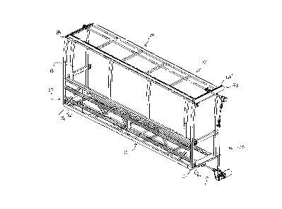
Figure 1 is a perspective view of the frame of a extendable room and the
synchronized drive system
in accordance with the invention;
Figure 2 is a perspective view of the pinion drive system in accordance with
the invention;

CA 02313854 2000-07-11
Figure 3 is an enlarged perspective view of the upper rack and pinion of the
drive system in
accordance with the invention; and,
Figure 4 is an enlarged perspective view of the lower rack and pinion of the
drive system in
accordance with the invention;

CA 02313854 2000-07-11
4
Detailed Description ojthe Inventian
With reference to Figure 1, the support and drive system for an extendable
room 12 is shown. The
room 12 includes appropriate structural members defining the bottom 14, sides
16 and 18, top 20 and
front 22 of the room and is constructed from appropriate structural members as
is understood by
those skilled in the art. With particular reference to the upper and lower
corner edges of the
extendable room 12, corner members 16a, 16b, 18a and 18b are a component of
the frame of the
extendable room for support of and interaction with a drive system 50 enabling
the room to be
extended and retracted from the main vehicle body.
The drive system ~0 includes a rack and pinion system operatively connected to
each of the corner
members 16a, 16b, 18a and 18b to provide uniform extension and retraction of
the extendable room
and support of the room within the main vehicle body (not shown).
With specific reference to Figure 2, the drive system 50 includes pinion
elements 51, 52, 53 and 54
located adjacent the corner elements 16a, 16b, 18a and 18b. Rack elements
16a', 16b', 18a' and 18b'
are incorporated into or are operatively connected to corner elements 16a,
16b, 18a and 18b. A drive
rod ~6 operatively connects lower pinion element 51 with lower pinion element
54 and drive rod 58
connects upper pinion element 52 with upper pinion element 53. The upper and
lower drive rods 56
and '.i8 are secured to the frame of the vehicle through bearing supports 56a,
56b, 58a, and 58b
respectively. Drive rod 56 synchronizes the rotation of pinion elements 51 and
54 with respect to one
another and drive rod 58 synchronizes the rotation of pinion elements 52 and
53 with respect to one
another.
In addition, the drive system 50 includes gear-box elements 60 and 62
operatively connected to the
drive rods 58 and 56 respectively to synchronize the rotation of the upper and
lower drive rods 56 and
58. Connection of the gear boxes 60 and 62 is achieved through vertical drive
rod 64. Preferably, in
order to permit offsetting of gear box 60 with respect to gear box 62,
flexible or universal couplings
66, 68 may be provided. Operation of the device is achieved through electric
motor 70 operatively
connected to one gear box.

CA 02313854 2000-07-11
Wil:h reference to Figures 3 and 4, details of the upper and lower rack and
pinion systems located at
each corner are shown. With specific reference to Figure 3, pinion 53 is shown
engaged with rack
53a located on corner member 16b. Support bearing 58a is shown engaged with
drive rod 58 with
flanges 58b for attachment to the main body of the vehicle (not shown).
Flanges 58b and 58c (Figure
2) are secured to the main vehicle body so as to prevent travel of pinions 52
and 53 with respect to
one another.
With specific reference to Figure 4,. pinion 51 is shown operatively engaged
with rack Sla on corner
member 18a. Pinion 51 and drive rod 56 are supported by bearing block 19 which
is fixedly attached
to the main vehicle body (not show:n). Accordingly, as can be seen from
Figures 1 and 4, pinions 51
and 54 and drive rod 56 support the extendable room structure within the
vehicle.
In operation, actuation motor 70 provides rotational input into gear box 62.
Gear box 62 drives gear
box 60, and together they simultaneously drive rods 56 and 58 through their
respective couplings.
The output of gear boxes 60 and 62 are equal with respect to one another. In
order to ensure that
linear travel of the upper and lower drive systems is synchronized,
appropriate mechanical gearing
withain gear boxes 60 and 62 is provided. In addition, an appropriate gearing
ration may be provided
to ensure electromechanical efficiency between the motor 70 and the output of
gear box 62.
In addition, appropriate electrical control of the actuation motor 70 may be
provided to automate the
extension or retraction of the extendable room. Such control may include
appropriately mounted
sensors on the extendable room and vehicle body which deactivate the actuation
motor 70 at specific
linear positions of the extendable room with respect to the vehicle body.
It is understood that various modifications may be made to the system without
departing from the
spirit and scope of the invention.

Dessin représentatif
Une figure unique qui représente un dessin illustrant l'invention.
États administratifs

2024-08-01 : Dans le cadre de la transition vers les Brevets de nouvelle génération (BNG), la base de données sur les brevets canadiens (BDBC) contient désormais un Historique d'événement plus détaillé, qui reproduit le Journal des événements de notre nouvelle solution interne.

Veuillez noter que les événements débutant par « Inactive : » se réfèrent à des événements qui ne sont plus utilisés dans notre nouvelle solution interne.

Pour une meilleure compréhension de l'état de la demande ou brevet qui figure sur cette page, la rubrique Mise en garde , et les descriptions de Brevet , Historique d'événement , Taxes périodiques et Historique des paiements devraient être consultées.

Historique d'événement

Description Date
Demande non rétablie avant l'échéance 2005-07-11
Le délai pour l'annulation est expiré 2005-07-11
Réputée abandonnée - omission de répondre à un avis sur les taxes pour le maintien en état 2004-07-12
Inactive : Page couverture publiée 2001-01-22
Demande publiée (accessible au public) 2001-01-20
Inactive : CIB attribuée 2000-08-31
Inactive : CIB en 1re position 2000-08-31
Lettre envoyée 2000-08-17
Inactive : Certificat de dépôt - Sans RE (Anglais) 2000-08-17
Demande reçue - nationale ordinaire 2000-08-15

Historique d'abandonnement

Date d'abandonnement Raison Date de rétablissement
2004-07-12

Taxes périodiques

Le dernier paiement a été reçu le 2003-04-11

Avis : Si le paiement en totalité n'a pas été reçu au plus tard à la date indiquée, une taxe supplémentaire peut être imposée, soit une des taxes suivantes :

  • taxe de rétablissement ;
  • taxe pour paiement en souffrance ; ou
  • taxe additionnelle pour le renversement d'une péremption réputée.

Les taxes sur les brevets sont ajustées au 1er janvier de chaque année. Les montants ci-dessus sont les montants actuels s'ils sont reçus au plus tard le 31 décembre de l'année en cours.
Veuillez vous référer à la page web des taxes sur les brevets de l'OPIC pour voir tous les montants actuels des taxes.

Historique des taxes

Type de taxes Anniversaire Échéance Date payée
Enregistrement d'un document 2000-07-11
Taxe pour le dépôt - générale 2000-07-11
TM (demande, 2e anniv.) - générale 02 2002-07-11 2002-04-30
TM (demande, 3e anniv.) - générale 03 2003-07-11 2003-04-11
Titulaires au dossier

Les titulaires actuels et antérieures au dossier sont affichés en ordre alphabétique.

Titulaires actuels au dossier
PREVOST CAR INC.
Titulaires antérieures au dossier
JEAN-PAUL CYR
NORMAND LESSARD
Les propriétaires antérieurs qui ne figurent pas dans la liste des « Propriétaires au dossier » apparaîtront dans d'autres documents au dossier.
Documents

Pour visionner les fichiers sélectionnés, entrer le code reCAPTCHA :


Pour visualiser une image, cliquer sur un lien dans la colonne description du document. Pour télécharger l'image (les images), cliquer l'une ou plusieurs cases à cocher dans la première colonne et ensuite cliquer sur le bouton "Télécharger sélection en format PDF (archive Zip)" ou le bouton "Télécharger sélection (en un fichier PDF fusionné)".

Liste des documents de brevet publiés et non publiés sur la BDBC .

Si vous avez des difficultés à accéder au contenu, veuillez communiquer avec le Centre de services à la clientèle au 1-866-997-1936, ou envoyer un courriel au Centre de service à la clientèle de l'OPIC.


Description du
Document 
Date
(aaaa-mm-jj) 
Nombre de pages   Taille de l'image (Ko) 
Dessin représentatif 2001-01-21 1 23
Description 2000-07-10 5 184
Abrégé 2000-07-10 1 16
Revendications 2000-07-10 2 65
Dessins 2000-07-10 4 132
Courtoisie - Certificat d'enregistrement (document(s) connexe(s)) 2000-08-16 1 120
Certificat de dépôt (anglais) 2000-08-16 1 163
Rappel de taxe de maintien due 2002-03-11 1 113
Courtoisie - Lettre d'abandon (taxe de maintien en état) 2004-09-06 1 178
Rappel - requête d'examen 2005-03-13 1 117