Note : Les descriptions sont présentées dans la langue officielle dans laquelle elles ont été soumises.
CA 02313915 2000-07-14
PATENT
NETWORK INTERFACE DEVICE
Cross Reference to Related Applications
The present application claims the benefit of priority of U.S. Provisional
Application Serial Number 60/143,949, filed on July 15, 1999.
Background of Invention
Descriution of Related Art
Current multi-line NIDs (Network Interface Devices) usually contain an
assembly
for many telephone lines with a stub input, an RJ-11 jack and plug for each of
the lines,
and screw terminal outputs. The NID is mounted on the side of a house or in a
basement
to of a building and functions as a demarcation point that separates
subscriber-owned wiring
from telephone company-owned (telco) wiring. The plug-and jacks in the NID
function
as the actual demarcation point for each of the lines. If the plug is removed
from the
jack, then the subscriber wires are physically and electrically disconnected
from the telco
wires. The plug-and jack allows the subscriber to plug his/her own telephone
into the
~5 jack to determine if the telco wires are working correctly. If there is a
dial tone at the
Nll~ but not in the subscriber's house or building, then the problem lies
between the NID
and the jack in the house or building. The subscriber is then responsible for
fixing the
problem. Alternatively, if there is no tone at the NID, then the telephone
company has a
problem with the line carrying signals to the NID. Therefore, the Nff~ allows
20 subscribers to determine if there are any problems on their line, whose
problems they are,
and potentially how to get them corrected.
HE0071
1
CA 02313915 2000-07-14
PATENT
The telco connection in the prior art N1D is also accomplished by means of
either
an RJ-21 connector on the rear of the unit or a stub. The NID usually includes
a hinged
cover with instructions on how to test the lines. There are also specific
areas for
recording identification or location numbers for each line. However, such
design causes
problems because, especially in the multi-line NIDs, the cost of the plugs and
jacks is
high; the subscriber may forget to plug the jack back in after testing,
thereby interrupting
service; and each of the lines is subject to being tampered with by others at
the
connection point.
Summary of the Invention
t 0 Accordingly, a network interface device is needed that alleviates the
problems
noted above by providing a more secure and lower cost device. Features and
advantages
of the invention will be set forth in the description which follows, and, in
part, will be
apparent from the description, or may be learned by practice of the invention.
The
objectives and advantages of the invention will be realized and attained by
the assembly
15 particularly pointed out in the written description and claims hereof, as
well as the
appended drawings.
To achieve these and other advantages, and in accordance with the purpose of
the
invention as embodied and broadly described herein, the present invention is
directed to a
network interface device including at least one pair of provider wires, at
least one pair of
20 customer wires, the customer wires being electrically connected to the
provider wires at a
junction, a switch in the proximity of the junction, and a pair of test
contacts having a
HE0071
CA 02313915 2000-07-14
PATENT
first end that is configured to be connected to a testing device and a second
end in the
junction, whereby the pair of provider wires is disconnected from the pair of
customer
wires and is electrically connected to the second end of the test contacts
upon activation
of the switch.
It is to be understood that both the foregoing general description and the
following detailed description are exemplary and explanatory and are intended
to provide
further explanation of the invention as claimed.
The accompanying drawings are included to provide a further understanding of
the invention and are incorporated in and constitute a part of this
specification, illustrate
t o one or several embodiments of the invention, and, together with the
description, serve to
explain the principles of the invention.
Brief Descriution of the Drawings
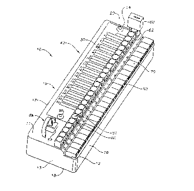
Fig. 1 is a perspective view of one embodiment of a NID constructed in
~ 5 accordance with the present invention.
Fig. 2 is a schematic of a portion of the NID of Fig. 1 illustrating the
connections
in the NID in a normal position.
Fig. 3 is a schematic of the test button of Fig. 2, with the test button in a
test
position (with the button depressed), thereby connecting the test circuit.
HE0071
CA 02313915 2000-07-14
PATENT
Figs. 4A and 4B show an alternate embodiment of the test button with the test
button in an open position in Fig. 4A, and the test button depressed in Fig.
4B, thereby
connecting the test circuit.
Fig. 5 is a perspective view of a third embodiment of the invention that
involves
the use of a push button switch and a printed circuit board.
Fig. 6 is a schematic of three test circuits constructed in accordance with
the
invention, the circuits being connected to a common ring test buss and tip
test buss,
which in turn connect to a single test port.
t o Detailed Description of The Invention
Fig. 1 shows a network interface device (N)?7) 10 that typically has a molded
thermoplastic housing 15 having a first top surface 11 and second top surface
12, a first
13 and second 14 end surface, a first 16 and second 17 side surface and a
bottom surface
18. Typically, the N1D also has a cover (not shown) that is hinged about one
side to
15 protect the subassembly 10 of the NID from the elements, tampering, etc.
The cover may
also have instructions on the use of the NID, either attached or molded to the
cover.
Sheet metal or structural plastic parts fastened together by conventional
methods well
known in the art could be used to create a viable housing as an alternative to
a molded
thermoplastic housing. Two tamper proof screws 20 are used to hold the
subscriber list
20 30 in place on the first top surface 12 of the housing to identify the
lines. A test jack 50
is shown with a dummy plug 52 inserted into the jack. A plurality of test
buttons 60 are
HE0071
4
CA 02313915 2000-07-14
PATENT
shown adjacent the list 30, each test button having a top surface 61 and a
hole 62 that
extends through the test button to provide a channel for inserting a padlock
80 to lock an
individual subscriber line by preventing the test buttons 60 from being pushed
downward,
as described in detail below. The test buttons are inserted through the top
surface of the
housing 15 to engage the wiring as discussed in detail below. Customer wires
65 (see
Fig. 6) are inserted into holes 90 of wire connectors 70, which are on the
second top
surface 12. Wire connectors 70 are shown in Fig. 1 in a representative way and
may take
many forms, including tool-less insulation displacement contacts (lDCs) and
screw
terminals, among others. The wire connectors 70 can attached to the housing 15
in a
variety of ways, including, for example, integrally molded, snap fit, etc.,
depending upon
design preference.
Fig. 2 schematically shows the wire connectors 70 connect to the test button
with
tip-out wire leads 120 and ring-out wire leads 140. Wire leads 120,140 can
also be
circuit trace leads or any other type of electrical conductors. The terminals
70 also
connect on the outside with the subscribers' equipment as shown, for example,
in Fig. 6.
Provider leads 110 and 130, which come from the provider's central office,
mechanically
and electrically connect to tip-out wire 120 and ring-out wire 140 to provide
telecommunications service to the subscriber through junction 166. When the
subscriber's service is interrupted, the location of the interruption must be
determined;
whether it is within the subscriber's (customer's) equipment or the provider's
line. If the
subscriber can test the provider's signal up to the Nm and the provider's
lines are
HE0071
5
CA 02313915 2000-07-14
PATENT
working, then the subscriber will know that the fault lies within the
subscriber's own
equipment or wiring. A test jack 50 having a pair of contacts is provided to
allow a
subscriber to directly connect to the provider's lines at the NID. To perform
the check,
the subscriber would remove dummy plug 52 from the test jack 50 and plug in a
telephone or other appropriate device. The plug 52 is a dummy plug in that,
contrary to
the prior art, it does not function to connect the provider's lines to the
subscribers' lines.
Rather, it has no electrical contacts and its only function is to keep dust,
dirt, and other
contaminants out of the test jack 50. Since the plug 52 is a dummy plug, if
the subscriber
forgets to plug it back in after testing the line, the only adverse affect is
that dust, dirt,
and other contaminants could get into the test jack. In the prior art, since
the plug-and-
jack connected the provider's lines to the subscribers' lines, if the
subscriber forgot to re-
insert the plug, there would be no service on the subscriber's line until the
plug was re-
inserted into the jack.
As an alternative embodiment, the jack 50 could be a dummy jack and the plug
52
15 could have the pair of contacts or connections. In this embodiment, the
subscriber would
insert the plug into the device to see if the signal was present on the
provider's lines. The
dummy jack's function would then be to hold the plug to protect it from
contaminants.
In order to perform the test as mentioned above, a test button 60 is provided
in the
N1D. As illustrated in Fig. 2, which shows the normal operating position of
test button
20 60, the test button 60 has two prong contacts 165, each positioned adjacent
a junction
166. The junction 166 comprises an engagement of the tip-in wire 110 with tip-
out wire
HE0071
6
CA 02313915 2000-07-14
PATENT
120 and ring-in wire 130 with ring-out wire 140. One side of each contact 165
is an
insulator 150 and the other side is a conductor 160. When test button 60 is
depressed as
illustrated in Fig. 3, insulator 150 on contacts 165 make contact with tip-out
wire 120 and
ring-out wire 140, and conductor 160 make contact with tip-in wire 110 and
ring-in wire
130. This breaks the connection between tip-in wire 110 and tip-out wire 120
and also
between ring-in wire 130 and ring-out wire 140. The contacts 165 push the
flexible
junction 166 apart, causing tip-in wire 110 and ring-in wire 130 to connect to
a buss bar
100 via tip test wire 180 and ring test wire 170, respectively. Buss bar 100
can be either a
pair of wire leads or trace leads that extend the length of the housing 15
(see Fig. 1) to
to connect with terminals (not shown) in the general area of the customer wire
leads. Test
wires 170 and 180, could also be traces or any other electrical conductor to
make
electrical connection to buss bar 100. Buss bar leads 172 and 182 in turn
connect the
buss bar 100 to test jack 50. Buss leads 172 and 182 could also be wires,
traces, or any
other electrical conductors. Since the signal from the provider lines 110, 130
are now
connected to the test jack 50 rather than to the subscriber's lines, a
subscriber/user can
insert a telephone or other appropriate device in the jack 50 to ensure that
the provider
lines 110, 130 are working correctly. The subscriber would then remove the
plug from
the test jack 50 and replace the dummy plug 52 after testing. The subscriber
would also
replace the lock 80 inserted through the holes b2 in the test button 60 The
lock 80
2o prevents others from pushing down on the test button 60 and disconnecting
the
subscriber's line from the provider's line.
HE0071
CA 02313915 2000-07-14
PATENT
Figs. 4A and 4B illustrate an alternative embodiment of the present invention.
In
this embodiment, as shown in Fig. 4A, the test wires are connected directly to
the
conductor 160 of contacts 165. When the test button 60 moves from the normal
position
to the test position (Fig. 4B), the junction 166 between the provider and
customer is
broken and the test wires 170, 180 are directly connected to the provider's
lines 110,130
through the contacts 165. Again, as with the embodiment above, the provider
lines 110,
130 can be tested by inserting a jack from a telephone or other appropriate
device into the
test jack 50. While the conductors 160 are shown coming from the top in Figs.
2 and 3
and the bottom in Figs. 4A and 4B, the conductors could come from any
orientation and
still fall within the scope of the invention.
Fig. 5 illustrates in a representative fashion an alternative embodiment of
the
present invention. A printed circuit board 250 has a representative button 220
that is
manually operated (e.g., a push button, a slide switch, etc.) that connects to
provider
wires 110,130 by provider tip and ring traces 214,216 on one side and to
subscriber wires
15 120,140 by tip and ring traces 210,212 on the other side. The button 220 is
also
connected to buss bar 100 by tip and ring traces 222,224. While only one
button is shown
for clarity purposes, the number of buttons that correspond to the lines in
the N1D, e.g.,
twenty five such buttons for twenty-five lines, would be mounted on a board
250. When
operated, button 220 activates a double pole, double throw switch, to connect
the
20 provider wires 110,130 to test jack 50 via the buss bar 100 and traces
222,224. The
buttons 220 are commercially available from a number of vendors.
HE0071
CA 02313915 2000-07-14
PATENT
Fig. 6 shows a schematic of another embodiment of the present invention that
includes the possibility of optional electronics included in the NID. The
schematic
illustrates three sets of wire connectors 70 (again, in a standard
configuration there would
be 25 wire connectors and associated circuits) to connect customer wires 6S to
provider
wires 110,130. In this embodiment, the switch 230 is the same as or similar to
that
illustrated in Figs. 2-5 and uses the button 60 discussed above to provide
connection to
the test port 50 by buss bar 100, through wires 170,180. This embodiment,
however,
includes optional electronics 240 in parallel to the rest of the circuit. The
optional
electronics may include a half-ringer, splitter circuit, maintenance
termination unit, etc.
If no electronics are provided, then the optional electronics circuit is an
open circuit. The
provider wires 110,130, typically in an outer covering or sheath 280, enter
the NID from
the building or from an outside location.
It will be understood that various changes in the details, materials and
arrangements of parts which have been herein described and illustrated in
order to
~ 5 explain the nature of the invention, may be made by those skilled in the
art within the
principle and scope of the invention as expressed in the appended claims.
HE0071
9