Note : Les descriptions sont présentées dans la langue officielle dans laquelle elles ont été soumises.
CA 02314029 2000-07-13
VTN-0492
.
REFLECTORS FOR UV RADIATION SOURCE
This invention claims the benefit of earlier filed US Provisional Application
No.
60/143,608 filed July 13, 1999 having the same title, incorporated herein by
reference, and this application is a continuation in part of US Serial No.
09/259,758, titled "Method of Sterilization", filed March 1, 1999 (VTN-388),
_- incorporated herein by reference.
FIELD OF THE INVENTION
This invention relates to a new reflector for a radiation source which
delivers ultraviolet radiation.
BACKGROUND OF THE INVENTION
US Patent 5,786,598 discloses the broad concept that a flash lamp
system might be used for deactivating microorganisms in containers including
a polyolefln container with a foil backing that contains a contact lens and a
preservative fluid. Although the patent discloses the idea of using a flash
lamp
system to sterilize contact lenses in a preserved solution in a container,
there
are no conditions defined to accomplish sterility, nor examples provided which
show that sterility can be accomplished.
U.S. Patents 5,034,235 and 4,871,559 disclose the use of intermittent
pulses of very intense, very short duration pulses of light to inactivate
microorganisms on the surface of food products, and suggests that the method
can be used for containers, medical devices, and food products in packages.
Efforts have been made to use a flash lamp system for sterilization of
contact lenses in containers; however, to date no system has been developed
that will consistently achieve the sterility required to provide a high
confidence
level in the system. In experimentation with a commercially available system
sterility was not achieved for all microorganisms under the normal operating
conditions. To increase the radiation intensity to the containers it was
necessary to increase the voltage applied to the flash lamps; however, this
shortened the lifetime of the lamps, and also damaged the container and
product materials. Further, anytime a lamp was changed, which was required
CA 02314029 2000-07-13
VTN-0492
more frequently due to the shortened life of the lamp, the lamp to lamp
variations in radiation intensity resulted in variations in the sterility
level that
was achieved. For the sterilization of a single-use contact lens, the USFDA
requires a minimum sterility assurance level (SAL) of 10$ (number of
microorganisms per container). A sterility assurance level of 10'~ is the
probability of having 1 non-sterile container out of one million containers.
__ Therefore, there still remains a need for a way to deliver high energy UV
radiation uniformly to a product for sterilization using a flash lamp system
that
is repeatable and capable of commercial use.
SUMMARY OF THE INVENTION
This invention provides a reflector for a high energy radiation system
wherein said reflector at least partially encompasses a radiation source
comprising a reflective material having a diffuse reflective surface which
reflects greater than 50 % of the radiation from 240-280nm which impinges
upon it. The reflector of this invention provides uniform UV radiation to a
target
area or volume. Not only is the radiation more uniform, but the diffuse
reflectors are able to reflect more of the radiation from a lamp which
impinges
upon the reflectors as compared to specular reflectors. The uniform UV
radiation allows the lamps to be used at lower voltages to deliver a minimum
quantity of radiation everywhere within a target volume which extends their
useful lives. The variability from lamp to lamp is decreased by the diffuse
reflector.
This invention also provides for a reflector or reflectors which are
elliptical in shape. If multiple elliptically shaped reflectors are used to
form a
reflective cavity, preferably where substantially all or all of the surfaces
of the
cavity are diffuse reflective surfaces, the bases of the reflectors where the
reflectors intersect to form the volume to be filled by the target are sized
to the
target, thereby providing minimal dead space. Dead space is where radiation
could otherwise pass by the target without impinging on the target. The design
of the reflectors maximizes the reflection of the radiation from the lamp to
the
target.
2
CA 02314029 2000-07-13
VTN-0492
The new reflectors make it possible to use a radiation system, preferably
a pulsed flash lamp system having these reflectors to sterilize products
including pharmaceutical, medical, and cosmetic products, and can be used in
an in-line mode in the manufacture of these products. The reflectors disclosed
herein which provide uniform radiation to a target can also be used for
photopolymerization, surface treatments and laser applications.
DESCRIPTION OF THE FIGURES
The invention will be described with reference to the following figures:
Figure 1 shows a cross-section of a radiation system having two
reflectors of this invention;
Figure 2 shows a cross-section of a radiation system having one
reflector of this invention;
Figure 3 shows a contour of the radiation energies in a target area using
a prior art reflector.
Figure 4 shows a contour of the radiation energies in a target area using
the same reflector used to generate the contour shown in Fig. 3, except that
the surface of the reflector had a diffuse coating applied to it.
Figure 5 shows a contour of the radiation energies in a target area using
a reflector having the shape shown in Fig. 1 and a diffuse coating.
Figure 6 is a graph which shows the Q Factor for a radiation system
having a cavity formed using two of the reflectors used to generate the
contour
shown in Fig. 3.
Figure 7 is a graph which shows the Q Factor for a radiation system
having a cavity formed using two of the reflectors used to generate the
contour
shown in Fig. 4.
Figure 8 is a graph which shows the Q Factor for a radiation system
having a cavity formed using two of the reflectors used to generate the
contour
shown in Fig. 5.
DESCRIPTION OF THE INVENTION
The term "ultraviolet radiation" or "UV radiation" means radiation having
a wavelength or wavelengths from 200 to 400nm. If a range is specked
3
CA 02314029 2000-07-13
VTN-0492
following the term "ultraviolet radiation" or "UV radiation", a narrower range
of
radiation is meant within the 200 to 400nm range. Further, the range
specified,
unless otherwise stated, means radiation having a wavelength or wavelengths
within the range.
The term "broad spectrum of radiation" means radiation having at least a
majority of the wavelengths from 20 to 1100nm wherein at least a portion of
the
-- radiation is UV radiation.
The phrase "to direct radiation towards a target" means to send
radiation towards a target by reflection, transmission or reflective-emission.
The directed radiation may reach the target directly, and/or indirectly minus
any
amounts which are attenuated intentionally or unintentionally. The "target" is
the medical device, container, or surface at which the radiation is directed.
This invention provides reflectors for use for a high energy radiation
source. A high energy radiation source that can be used with the reflectors of
this invention includes discrete or continuum producing, incoherent lamps,
such as flash lamps, arc lamps, lasers (continuous or non-continuous),
deuterium lamps, or continuous wave light sources, e.g. xenon gas or mercury
vapor light sources. The UV radiation sources are high energy, that is, they
generate greater than 0.1 J/cm2 per pulse for a flash lamp or 20 watts/cm2for
a
continuous radiation source, preferably of which at least 1 percent of the
radiation is from 240 to 280nm. The presently preferred UV radiation source is
a flash lamp system, having any number of lamps, e.g. one to six lamps, which
produces at least 1 J/cm2 broad spectrum radiation (100 - 3000nm) per flash of
which at least 10 mJ/cmZ per flash is UV radiation. The preferred application
of
this invention is in a flash lamp system for the sterilization of contact
lenses
(target). US Serial No. 09/259,758, titled "Method of Sterilization", VTN-388,
incorporated herein by reference, discloses more details of the method of
sterilizing contact lenses. The radiation from 240 to 280nm is the most
effective range for the sterilization of microorganisms, with many references
indicating that 254nm is the peak of that range.
The reflector comprises a reflective material and a diffuse reflective
surface. The reflector reflects greater than 50 %, more preferably greater
than
75 %, and most preferably greater than 90 % of the radiation from 240 to
4
CA 02314029 2000-07-13
VTN-0492
280nm which impinges upon it. Many of the reflectors of this invention using
the materials described herein reflect greater than 95% of the radiation from
240 to 280nm. For some embodiments the reflective material reflects greater
than 50 %, more preferably greater than 75 %, and most preferably greater
than 90 % of the radiation from 250 to 270nm which impinges upon it. The
ranges 240 to 280nm, and 250 to 270nm will be referred to as the desired
-- ranges, the reflector may or may not reflect additional radiation outside
the
ranges specified, but at a minimum will reflect the specified percentages of
the
radiation within the desired ranges. The amount of reflected radiation may
include radiation which is absorbed by the reflector and re-emitted at
different
wavelengths within the desired ranges. It is preferred that the reflector
reflects
at least a portion of all the wavelengths of desired radiation which impinges
upon it. The reflective materials may not reflect all the wavelengths within
the
desired ranges at a single percentage, so certain reflective materials will be
better suited for some applications than others. Mixtures of the reflective
materials can be used to achieve improved reflection at certain or all of the
wavelengths in the desired ranges.
The reflectors of this invention preferably provide a Quality Factor, ("Q")
greater than 1.7 , preferably greater than 2 most preferably greater than 3 .
The Quality Factor is defined as the ratio of the total energy measured in the
target area from all the radiation sources and their reflectors configured in
a
closed cavity divided by the summation of the energy from each lamp and
reflector measured individually in the target area or volume of an open
cavity.'
For the preferred embodiment comprising two reflectors and two lamps, the Q
is greater than 3, preferably greater than 4, and most preferably greater than
5.
The reflective materials which are part of the reflector reflects radiation
from a radiation source to a target. The target can be any material which is
to
be effected by the radiation for the purpose of, for example, sterilization,
photoactivation, surface treatments, photopolymerization, etc. The target can
be, for example, products, particularly a medical product, polymers, monomers,
laser medium, and dyes. The preferred target is a medical product for
sterilization. The reflector of this invention is shaped to direct the desired
radiation toward the target. Preferably one or more of the reflectors of this
5
CA 02314029 2000-07-13
VTN-0492
invention are used in a radiation system comprising one or more lamps.
Preferably the reflector or reflectors substantially encompass or at least
partially encompass the radiation source or sources of the radiation.
Preferably the reflectors encompass at least 180° from the centerline
of the
lamp. Additionally, the reflector or reflectors preferably encompass the
target
too. It is preferred that the reflector or reflectors preferably form a
cavity,
-- tunnel, hollow sphere, or chamber encompassing the target area or volume
which is sized to be substantially the size and shape of the target, such that
the
amount of radiation that can pass from one reflector to another reflector or
from
one surface to another surface of the reflector located on opposite sides of
the
target without going through or being absorbed by the target is minimized.
Preferably less than 50 percent more preferably less than 25 percent and most
preferably less than 10 percent of the total radiation produced by each
radiation source will be able to pass by the target without going through or
being absorbed by the target. The target area or volume is located at the
focal
point or plane of the reflector(s). The reflector reflects the desired
radiation
towards the target either directly or indirectly, that is, the desired
radiation may
impinge an apparatus before striking the target, e.g. another surface of the
reflector or reflectors, minors, fiber optics, or the like.
The diffuse reflectors of this invention deliver a uniform amount of
radiation, at least of the desired radiation, to a target area or volume. A
uniform amount of radiation means that the variation in the levels of the
energy
within the target area and/or volume is less than 8 mJ/cm2, more preferably '
less than 6 mJ/cm2, most preferably less than 5 mJ/cm2. The variation in the
levels of the energy within the target area or volume is less than 15 percent,
more preferably less than 10 percent, most preferably less than 5 percent.
Therefore, for two radiation systems having equivalent radiation sources
encompassed by reflectors) to form a treatment cavity having a target area or
volume, the only difference being the types of reflectors, the system using
the
diffuse reflectors) will typically provide at least an equivalent average
amount
of radiation to a target area or volume, and a more uniform amount of
radiation
in the target area or volume.
6
CA 02314029 2000-07-13
VTN-0492
The diffuse reflectors also provide radiation at a broader array of angles
with the benefit, in the preferred embodiment, that there is a smaller chance
that microorganisms will escape the radiation. When specular reflectors are
used the angle of incidence of the radiation is not as varied increasing the
likelihood that microorganisms may be shielded from the radiation by other
microorganisms, or by refracting, diffracting, or reflecting elements within
the
-- package. The angle of incidence to a target area or volume for a system
having one or more specular reflectors is from one-half degree to 6 degrees.
For a system having one or more reflectors of this invention, the angles of
incidence comprise angles from 40 to 180 degrees. The greater variance in
the angle of incidence in the radiation to the target which is more lethal to
the
microorganisms, and provide for a larger contrast ratio. The contrast ratio is
the ratio of the intensity of radiation in an unobstructed (empty) target area
or
volume to the intensity of radiation for an obstructed target area or volume.
An
obstructed target area or volume is one in which there is one or more elements
present in the target area or volume which diminish intensity due to
absorption,
reflection, refraction, defraction, or scatter. Examples of such elements
include
lenses, packaging, microorganisms, bubbles, surface geometries, etc.. The
radiation can be measured using the monitoring system described in Ebel, et
al, US Patent Application (VTN-443) entitled "Sterilization
System", incorporated herein by reference. The obstructed measurement of
radiation can be made by placing a sensor within the packaging. The reflectors
of this invention provide a contrast ratio of less than 1.5 in the target area
or -
volume. This can be compared to a specular reflector which would provide a
contrast ratio of greater than 10.
The preferred reflective materials for the diffuse reflectors of this
invention include, but are not limited to, alkaline metal compounds (oxides
and
halides), heavy metal oxides (e.g. barium), divalent metal oxides (e.g.
magnesium), and polyvalent metal oxides (e.g. ytterbium or aluminum).
Reflective materials can also be selected according to the following formula
MaObX~Hd wherein M is a single metal or a mix of metals, preferably a rare
earth metal, O is oxygen, X is a heteroatom such as sulfur, nitrogen and
phosphorous or the like, and H is a halide, preferably fluorine, a is 1 to 20,
7
CA 02314029 2000-07-13
VTN-0492
preferably 1 to 12, b is 0 to 20, preferably 0 to 12, c is 0 to 20, preferably
0 to
12, and d is 0 to 20, preferably 0 to 12, with the proviso that at least b, c
or d is
at least 1. These materials need to be of sufficient purity such that the
levels of
impurities do not degrade the reflector performance. Preferably the materials
are more than 99.9 % pure, more preferably more than 99.99 % pure.
Examples of useful reflective materials are listed in Table 1. Included in
Table
__ 1 are the mean percent reflectivities of the reflective materials. The
percent
reflectivities were determined by packing a dry powder sample of solid
material
into a cuvette, and putting the cuvette into a spectrophotometer having an
integrating sphere which measured the radiation reflected from the sample.
Table 1. Reflective Materials
Observe %R %R %R %R %R %R
d
Visual Mean Std Dev Mean Std Dev Mean Std Dev
M t vial Color ~0,~- 2~Q- 240- 40- ?~- 2
ann dnn ~Qn ~o~ "." -
".,. .. c~rv
Aluminum Oxide White 93.39 4.93 90.53 0.43 87.24 3.58
Barium Sulfate White 100.09 1.71 100.8 0.27 101.033.53
Barium Titanate Beige 18.55 10.1114.42 0.27 21.44 9.04
Cerium Oxide Beige 62.69 26.6355.84 18.08 23.08 11.18
Erbium Oxide Pink 62.69 26.6355.84 18.08 23.08 11.18
Europium Oxide White 54.79 34.3 45.1 1.26 23.78 10.73
Germanium Dioxide White 84.13 21.3272.83 10.51 50.72 14.64
Hafnium Oxide Beige 32.26 7.49 25.83 0.51 31.04 9.69
Holmium Oxide Pink 66.75 27.3767.18 20.46 20.88 9.31
Lanthanum Oxide White 82.99 28.3988.23 11.97 29.49 12.36
Magnesium FluorideWhite 100.44 6.12 95.79 0.75 110.287.2
Magnesium Oxide White 97.27 14.21101.44 0.52 19.68 24.49
Praseodymium OxideBlack 13.67 5.59 12.13 0.33 20.7 9.49
Samarium Oxide L. Yellow68.84 27.6251.32 23.08 27.58 6.59
Tellurium Oxide White 35.95 22.2418.56 0.39 28.1 11.42
Terbium Oxide Brown 13.11 6.09 11.55 0.58 21.15 9.99
Titanium Dioxide White 14.92 5.17 13.12 0.28 20.75 9.14
Ytterbium Oxide White 70.72 33.1645.8 26.02 23.2 11.84
Yttrium Oxide White 85.81 24.1489.38 6.51 41.14 15.4
Zinc Oxide White 15.85 13.3910.99 0.35 20.72 11.36
8
CA 02314029 2000-07-13
VTN-0492
In the formula for the reflective materials, when a is 1 to 6 and b is 2 to
11, and c and d are 0 then the reflective materials is a metal oxide, such as
calcium oxide (Ca0) and hafnium oxide (Hf02), lanthanum oxide (La203),
terbium oxide (Tb40,), and barium titanate (BaTi03). An example of reflective
material for which a is 1 and d is 2 and b and c are 0 is magnesium fluoride
(MgF2). Additional examples of reflective materials include magnesium oxide
-- (Mg0), aluminum oxide (AI203) barium oxide (Ba0), barium titanate (BaTi03),
holmium oxide (Hoz03), calcium oxide (Ca0), lanthanum oxide (La203),
germanium oxide (Ge02), tellurium oxide (Te02), europium oxide (Eu203),
erbium oxide (Er203), neodymium oxide (Nd203), samarium oxide (Sm203),
ytterbium oxide (Yb203), yttrium oxide (Y203), magnesium fluoride (MgF2),
barium sulfate (BaS04), and dysprosium oxide (Dy203). Other examples
include refractory oxides of other rare earths, rare earth halides and
metallic
combination oxides. The preferred reflective materials are magnesium oxide,
magnesium fluoride, aluminum oxide, barium sulfate, lanthanum oxide, yttrium
oxide, and ytterbium oxide, and the most preferred are magnesium oxide,
magnesium fluoride, aluminum oxide and barium sulfate.
The preferred shape for the reflectors is elliptical. For a single elliptical
shaped reflector the target area or volume and the location of the lamp are
preferably at the foci of the ellipse. For a radiation system having more than
one reflector, which preferably intersect to form a cavity, the target area or
volume is preferably located at or encompasses the foci of the ellipses, and
the
one or more lamps are located at the opposite foci of the ellipses. In the
preferred design, having two elliptically shaped reflectors, the foci of each
reflector opposite the lamps is at a different location within the target
volume.
In the preferred design (shown in Fig. 1 ) the foci of the lower reflector is
at the
top of the target volume and the foci of the top reflector is at the bottom of
the
target volume.
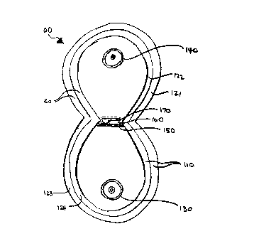
Fig. 1 shows two diffuse reflectors 110 and 120 of this invention for use
in a radiation system 100, e.g. a flash lamp system 100. (More information on
flash lamp systems can be found in US Patents 4,464,336; 5,034,235; and
4,871,559, incorporated herein by reference.) The radiation system comprises
reflectors 110 and 120, and flash lamps 130 and 140. Reflector 110
s
VTN-0492
CA 02314029 2000-07-13
substantially encompasses flash lamp 130. Reflector 120 substantially
encompasses flash lamp 140. Flash lamps 130, 140 are located at one foci of
each reflector 120, 130, respectively. Reflectors 110 and 120 encompass the
target volume 160 (shown in dashed lines) in which the target 170 is placed.
The second foci (not shown) of reflectors 120, 130 are within the target
volume.
As shown, the reflectors are shaped to provide a target volume which allows
__ minimal radiation to pass from one reflector to another reflector without
passing through the target. The target 170 is a contact lens container
containing a contact lens (not shown) and solution (not shown). The target 170
is held in place by a target support 150 which defines the bottom of the
target
volume 160. The target support 150 is a transparent glass, crystalline
material,
quartz plate or the like 150. In Fig. 1, the flash lamp system 100 is shown
having a vertical configuration; however, the system can be rotated by any
number of degrees; however, the target support 150 might have to be modified
or changed to for example, a hook, conveyor, or hollow block to accommodate
the target 170. Alternatively, there can be any number of reflectors to direct
the radiation at the target. Preferably the reflectors are designed to form a
closed cavity, which can be opened via a door or the like to place the target
within the cavity, the treatment with radiation can occur when the cavity is
closed, and then the cavity can be opened or otherwise accessed to remove
the target after treatment. When the cavity is closed, the cavity is light-
tight.
The reflectors are shown having the same size and shape; however,
they can differ if desired. As shown, the reflectors 110 and 120 each comprise
a reflector support 121, 123 and a reflective coating 122, 124. The reflective
coatings 122, 124 can be made of any reflective material which provides a
diffuse reflective layer. The reflective coatings 122, 134 are shown as a
single
layer, but the coatings 122, 124 can comprise multiple layers of various
- reflective materials, if desired.
The reflective coatings 122, 124 can be the same or different and can
be applied by painting, spraying, dipping, casting, conversion coating, gel
coating, etching, chemical vapor depositing, sputtering, plasma spraying,
laser-
deposition, or chemical or mechanical bonding, e.g. by adhesives of a film
comprising the attenuating materials to the reflector support 121, 123. The
CA 02314029 2000-07-13
VTN-0492
preferred method of applying the reflective coatings is to paint or spray
reflective materials onto the reflector support 121, 123. To paint or spray
them
onto the support 121, 123, an aqueous or non-aqueous suspension is formed
preferably comprising reflective material and binder. Useful binders are
polymeric, inorganic or sol-gels, more preferably inorganic or sol gel, and
most
preferably inorganic. The preferred suspension comprises 0.1 to 50 % by
-- weight binder, 0.1 to 99.9 % by weight reflective material, and 0.1 to 90 %
by
weight carrier. The carrier is a liquid used to form a dilution of the
reflective
materials and binder to apply the coating. Examples of useful carriers are
water, alcohols, alkanes, freons, and the like, most preferably water.
Examples of polymeric binders useful in making coatings comprising
reflective materials are polyvinyl alcohols, cyanoacrylates, acrylics, and
silicones. Presently the polymeric binders are limited in their use, because
they tend to degrade in the high energy UV radiation. Examples of inorganic
1 S binders useful in making coatings comprising reflective materials are
sodium
silicate, low-temperature sintered glasses, alkali oxide silicates, such as
sodium, potassium and lithium silicates. Examples of sol gel binder precursors
useful in making coatings comprising reflective materials are aluminum tert
butoxide, sodium silicate, tetraethylorthosilicate (TEOS), metal
isopropoxides,
dysprosium ethylhexano-diisopropoxide in isopropanol, dysprosium 2-
ethylhexanoate in hexane, dysprosium isopropoxide in toluene-isopropanol,
dysprosium 2-methoxyethoxide in 2-methoxyethanol, erbium ethylhexano-
diisopropoxide in isopropanol, erbium 2-ethylhexanoate in hexane, erbium
isopropoxide in toluene -isopropanol, holmium ethylhexano-diisopropoxide in
isopropanol, holmium isopropoxide in toluene -isopropanol, holmium 2-
methoxyethoxide in 2-methoxyethanol, lanthanum acetate, lanthanum 2-
ethylhexanoate in hexane, lanthanum isopropoxide, lanthanum 2-
methoxyethoxide in 2-methoxyethanol, magnesium ethoxide in ethanol,
magnesium methoxide in methanol, magnesium 2-methoxyethoxide in 2-
methoxyethanol, neodymium ethylhexano-diisopropoxide in isopropanol,
neodymium 2-ethylhexanoate in hexane, neodymium isopropoxide in toluene -
isopropanol, neodymium 2-methoxyethoxide in 2-methoxyethanol, samarium
ethylhexano-monoisopropoxide in toluene isopropanol, samarium 2-
CA 02314029 2000-07-13
VTN-0492
ethylhexanoate in hexane, samarium isopropoxide in toluene -isopropanol,
samarium 2-methoxyethoxide in 2-methoxyethanol, ytterbium isopropoxide in
toluene-isopropanol, ytterbium 2-methoxyethoxide in 2-methoxyethanol, yttrium
ethylhexano-diisopropoxide in toluene-isopropanol, yttrium ethylhexano-
monoisopropoxide in toluene-isopropanol. The preferred sol gel precursors are
erbium ethylhexano-diisopropoxide in isopropanol, erbium 2-ethylhexanoate in
-- hexane, erbium isopropoxide in toluene -isopropanol, holmium ethylhexano-
diisopropoxide in isopropanol, holmium isopropoxide in toluene -isopropanol,
holmium 2-methoxyethoxide in 2-methoxyethanol, lanthanum acetate,
lanthanum 2-ethylhexanoate in hexane, lanthanum isopropoxide, lanthanum 2-
methoxyethoxide in 2-methoxyethanol, magnesium ethoxide in ethanol,
magnesium methoxide in methanol, magnesium 2-methoxyethoxide in 2-
methoxyethanol, samarium ethylhexano-monoisopropoxide in toluene
isopropanol, samarium 2-ethylhexanoate in hexane, samarium isopropoxide in
toluene -isopropanol, samarium 2-methoxyethoxide in 2-methoxyethanol,
ytterbium isopropoxide in toluene-isopropanol, ytterbium 2-methoxyethoxide in
2-methoxyethanol, yttrium ethylhexano-diisopropoxide in toluene-isopropanol,
yttrium ethylhexano-monoisopropoxide in toluene-isopropanol. The more
preferred sol gel precursors are lanthanum acetate, lanthanum 2-
ethylhexanoate in hexane, lanthanum isopropoxide, lanthanum 2-
methoxyethoxide in 2-methoxyethanol, ytterbium isopropoxide in toluene-
isopropanol, ytterbium 2-methoxyethoxide in 2-methoxyethanol, yttrium
ethylhexano-diisopropoxide in toluene-isopropanol, yttrium ethylhexano-
monoisopropoxide in toluene-isopropanol.
Some of the binders can be used alone as the reflective materials,
particularly the sol gels which can be applied as described above in a
suspension or sintered to form a reflective composition, either coating or
solid
- block. Examples of binder precursors which can be used alone as the
reflective materials include dysprosium isopropoxide, dysprosium ethylhexano-
diisopropoxide in isopropanol, dysprosium 2-ethylhexanoate in hexane,
dysprosium isopropoxide in toluene -isopropanol, dysprosium 2-
methoxyethoxide in 2-methoxyethanol, erbium ethylhexano-diisopropoxide in
isopropanol, erbium 2-ethylhexanoate in hexane, erbium isopropoxide in
12
CA 02314029 2000-07-13
VTN-0492
s
toluene -isopropanol, holmium ethylhexano-diisopropoxide in isopropanol,
holmium isopropoxide in toluene -isopropanol, holmium 2-methoxyethoxide in
2-methoxyethanol, Lanthanum acetate, Lanthanum 2-ethylhexanoate in
hexane, Lanthanum isopropoxide, Lanthanum 2-methoxyethoxide in 2-
methoxyethanol, Magnesium ethoxide in ethanol, Magnesium methoxide in
methanol, Magnesium 2-methoxyethoxide in 2-methoxyethanol, Neodymium
__ ethylhexano-diisopropoxide in isopropanol, Neodymium 2-ethylhexanoate in
hexane, Neodymium isopropoxide in toluene -isopropanol, Neodymium 2-
methoxyethoxide in 2-methoxyethanol, Samarium ethylhexano-
monoisopropoxide in toluene isopropanol, Samarium 2-ethylhexanoate in
hexane, Samarium isopropoxide in toluene -isopropanol, Samarium 2-
methoxyethoxide in 2-methoxyethanol, Ytterbium isopropoxide in toluene-
isopropanol, Ytterbium 2-methoxyethoxide in 2-methoxyethanol, yttrium
ethylhexano-diisopropoxide in toluene-isopropanol, Yttrium ethylhexano-
monoisopropoxide in toluene-isopropanol.
Alternatively, the reflective coatings described above can comprise any
of the reflective materials and binders listed above which are formed in the
shape of a film and then chemically or mechanically bonded to a reflector
support. Alternatively, the reflective materials can be combined with metal
oxides or powdered glass and sintered to form films of the reflective
materials
which can be chemically or mechanically bonded to a reflector support. As
stated above, the most prefer-ed reflective materials are barium sulfate,
aluminum oxide, magnesium fluoride, and magnesium oxide.
The reflective coatings are preferably applied to form a coating having a
thickness from 0.1 to 2500 microns. (A coating greater than 2500 microns is
considered a block of the material). The coatings are preferably applied in
multiple layers of the same attenuating material(s), preferably using the same
coating composition.
The reflector supports 121, 123 can be non-reflective reflector supports
or reflective reflector supports which can comprise additional coatings, such
as
films or foils onto which the one or more reflective coatings described above
are applied. Reflective supports can be diffuse or specular. Reflective
supports can comprise metal. An example of a reflective reflector support is a
13
CA 02314029 2000-07-13
VTN-0492
metal, such as, solid polished aluminum, which is thick enough to hold its
shape, and is bolted or otherwise mounted into place encompassing the lamp,
or is a film, e.g. a vapor-deposited specular metal sheet, which is adhered to
another part having the desired reflector shape to form a reflective reflector
support. The reflective reflector support can also be made from solid blocks
comprising reflective materials onto which the reflective coating can be
applied.
_- Reflectors comprising solid blocks of the reflective materials will be
described
below.
Almost any material can be used as a non-reflective reflector support
including wood, polymers, metals and ceramics.
In an alternative embodiment, the diffuse reflector of this invention can
comprise formed solids comprising the reflective materials. The formed solids
can be formed by combining the reflective materials with metal oxides or
powdered glass, and sintering them to form the reflector. The reflective
materials and metal oxides or powdered glass are sintered in the shape of the
reflector. Alternatively, the reflector can be made by combining the
reflective
materials with binders and forming a formed solid either in the shape of the
reflector or not in the shape of the reflector and subsequently machining the
formed solid into the shape of the reflector. Alternatively, a glass reflector
can
be formed by adding the reflective materials as a dopant to the feed stock
used
to make a quartz, crystalline material, sapphire, or UV radiation-transparent
glass in the shape of the reflector.
Fig. 2 shows an alternative embodiment of this invention. In Fig. 2 the-
radiation system shown comprises a single lamp and a single reflector 220.
The reflector 220 encompasses both the lamp and the target. The target
volume 260 is at the foci, focal point or plane of the reflector (shown in
dashes), and is where the target 270 is placed. The target 270 is a contact
lens container. The reflector 220 comprises a reflector support 221, a
material
layer 210 and a transparent support 201. The transparent support 201 is
transparent to at least a portion of the radiation which impinges upon it,
preferably the desired radiation. The transparent support 201 preferably
comprises glass, quartz, sapphire, crystalline material or the like. The
reflector
support 221 can comprise any of the combinations of reflective or non-
14
CA 02314029 2000-07-13
VTN-0492
reflective supports, or coatings on the supports as described above. The
material layer 210 comprises one or more reflective materials, and/or can be
any of the compositions comprising reflective materials as described above;
however, this embodiment is particularly suited for reflective materials that
will
not stay in place without the presence of the transparent support 201, such as
a packed powder. The material layer 47 preferably has a thickness from 0.1 to
-_ 2500 microns.
Also shown in Fig. 2 in the radiation system 200 is an optional reflective
blocking element 202. The reflective blocking element 202 can be used to
provide more uniform radiation to a target area or volume particularly in a
situation where the direct radiation from the radiation source is non-uniform.
To prevent the radiation from the radiation source from striking the target
directly, the reflective blocking element 202 is placed between the radiation
source 240 and the target 270. The reflective blocking element 202 preferably
has a simple geometric form, more preferably an optically concentrating form,
and most preferably an integral form of the reflecting optics. Examples of
useful shapes are a triangle (shown in Fig. 2) and a half circle. It is
preferred
that the reflective blocking element is a diffuse reflector comprising the
reflective materials described herein. The reflective blocking element can
comprise any of the reflector compositions described herein. Preferably, the
blocking element is sized to occlude any direct radiation from the radiation
source to the target.
All the difhrse reflectors described herein can comprise optional
attenuating materials as a coating on the reflector, or as an additive to the
reflector compositions. Attenuating materials are used to attenuate undesired
radiation from the radiation which is produced by the radiation source and
eventually reaches the target. Attenuating materials and ways to add the
attenuating materials to a radiation system are disclosed and described in
concurrently filed, Kimble et al, US Serial No. , titled "UV Radiation
System Having Materials for Selectively Attenuating Radiation" (VTN-0462),
incorporated herein by reference. Any of the attenuating materials and the
ways of incorporating the attenuating materials into a radiation system
disclosed therein can be used with the reflectors herein. In fact, some of the
CA 02314029 2000-07-13
VTN-0492
attenuating materials disclosed in the referenced application are reflective
materials useful in this invention. Because some of the reflective materials
reflect some wavelengths of radiation and absorb other wavelengths of
radiation, careful selection of reflective materials may provide for the
attenuation of undesired radiation. For the preferred use of the reflectors of
this invention, that is, in a radiation system which sterilizes contact
lenses, the
radiation from 100 up to 240nm which damages the contact lens polymers is
preferably attenuated. It is preferred to attenuate greater than 30 %, more
preferably greater than 60 % and most preferably greater than 90 % of the
undesired radiation from the radiation to the contact lens polymers. Examples
of reflective materials which also attenuate the radiation from 100 up to
240nm
are magnesium oxide, lanthanum oxide, ytterbium oxide, and yttrium oxide.
The uniformity in the radiation directed to the target area or volume is
greatly improved using a diffuse reflector having any shape compared to a
specular reflector having the same shape. In addition the quantity of the
radiation can be increased by diffuse reflector or reflectors which at least
partially encompass the lamp or lamps, even more preferably at least
substantially encompass the lamps) and the target, forming a cavity or
chamber, preferably a closed cavity in which all the radiation is directed
toward
the target by the lamps and the reflective surfaces of the cavity. The one or
more reflectors can have a cylindrical, polygonal, parabolic or elliptical
shape;
however, the preferred shape is an elliptical shape. Elliptical reflectors are
shown in Figs. 1 and 2. The prior art reflectors are specular and have
straight
sides which cause a large loss in the radiation, particularly when the
radiation
hits the straight sides at a small angle of incidence. The preferred radiation
system comprises two elliptically-shaped reflectors which have a target volume
with minimal space between the reflector cavity and the target to minimize the
amount of radiation which passes from one reflector to the other without
hitting
the target. However, any configuration of one or more diffuse reflectors
provide the benefits described herein.
Example and Comparative Exam les
CA 02314029 2000-07-13
VTN-0492
A spectroradiometric monitoring system was used to measure the
radiation within the desired range of 240 to 280nm in a target area that two
prior art reflectors and a reflector of this invention, individually and in
pairs,
directed at the target area using a pulsed radiation system. The monitoring
system is further described in Ebel, et al, US Patent Application
(VTN-443) entitled "Sterilization System", earlier incorporated by reference.
__ The monitoring system disclosed in Ebel et al, can measure the
spectroradiometric output of each flash. The reflectors were mounted in pairs
into the same radiation system, and the spectroradiometric measurements
were performed. The reflectors all had the same parabolic shape. The
radiation system was a PurePulse PBS1-4 system (manufactured by
PurePulse Technologies, Inc., San Diego, CA) which consisted of two flash
lamp assemblies connected in series, each of the flash lamp assemblies
consisted of a lamp, and a reflector partially encompassing the lamp. The
PBS1-4 system consists of a pulse-generator capable of generating a large
pulse of energy by virtue of its large capacitance (80-160 p,F) and high
potential (greater than 6 kV), and control circuits. Both lamps generate a
broad
spectrum of radiation which includes ultraviolet, infrared and visible light.
For
two of the three measurements made for this example using the reflectors
described below, the radiation from the second lamp and reflector was isolated
from the first lamp and reflector (for which the measurements were made) by
using an aluminum sheet between the lamp assemblies. The first
measurements made were used to generate a contour plot of the radiant
energy per flash for one lamp and one reflector (one lamp assembly) in the
target area 21 mm from the lamp assembly's protective window.
After generating the contour plot, the radiant energies at one point
(where an integrating sphere was placed) 21 mm away from the lamp was
measured for one lamp and one of each of the reflectors described below as
the voltage to the lamp was varied. The total measured radiant energy from
240 to 280nm was plotted as a function of the voltage. Then, the just-
described steps were repeated except that both lamp assemblies, each
consisting of a lamp and a reflector described below, were used to measure
the total radiant energy from 240 to 280nm at the same point. (The aluminum
CA 02314029 2000-07-13
VTN-0492
sheet between the lamp assemblies was removed.) The total measured
radiant energy from 240 to 280nm was plotted as a function of the voltage on
the same graph as when the radiant energy from only one lamp assembly was
measured.
A blocking element was not part of the radiation system.
Prior Art Reflector A was a shaped aluminum reflector having a vapor
__ deposited layer of aluminum on which was a coating of silicon monoxide for
protection, provided by the manufacturer of the PBS1-4 System. A contour
plot of the radiant energy using the Prior Art Reflector A is shown in Fig. 3.
Fig.
6 shows the a curve of the total energy from 240 to 280nm at different lamp
voltages measured for one lamp assembly using the Prior Art Reflector A, and
a second curve of the total energy in the cavity formed by both lamp
assemblies and having straight sides between the lamp assemblies using the
Prior Art Reflector A.
Reflector B was made by modifying the Prior Art Reflector A by adhering
a thin sheet of a specular aluminum foil, coated with an antioxidative
protective
layer onto Prior Art Reflector A. The specular aluminum foil material used is
called a Light Sheet. A contour plot of the radiant energy directed into the
target area of the lamp using the Prior Art Reflector B is shown in Fig. 4.
Fig. 7
shows a curve of the total energy from 240 to 280nm at different lamp voltages
measured for one lamp assembly using the Prior Art Reflector B, and a second
curve of the total energy in a cavity formed by both lamp assemblies using the
Reflector B. Reflector B provides a more uniform level of energy than Prior
Art
Reflector A.
Reflector C was made by modifying the Prior Art Reflector A by coating
it with BaS04. The surface of the Prior Art Reflector A was first blasted with
small glass beads. A barium sulfate coating composition was prepared by
mixing 1 part by weight sodium silicate (binder), 10 parts by weight barium
sulfate (reflective material) and 10 parts by weight water (carrier). Twenty
layers of the coating composition were sprayed onto the aluminum substrate.
Each coating was air dried between coatings. A contour plot of the radiant
energy directed into the target area of the lamp using the Reflector C is
shown
in Fig. 5. Fig. 8 shows the a curve of the total energy from 240 to 280nm at
18
CA 02314029 2000-07-13
VTN-0492
-i
different lamp voltages measured for one lamp assembly using the Reflector C,
and a second curve of the total energy in a cavity formed by both lamp
assemblies using the Reflector C.
The contour plot of the Reflector C (Fig. 5) shows the increase in
uniformity of the energy that the difhrse reflector directs at the target area
as
compared to the Prior Art Reflector A and Reflector B (Fig. 3 and 4) Greater
__ uniformity decreases the chances that microorganisms can avoid the minimum
dose required for sterilization. The circles on the contour plots represent
the
target, that is, 12 contact lens containers which can be removably-attached to
each other. These removably-attached containers are commonly used to
configure multi-packs of contact lens containers.
Figure 8, compared to Figure fi, shows that the preferred diffuse
reflector of this invention when used to at least partially encompass the
lamps)
and the target area or volume, although more preferably used to form a cavity,
more preferably a closed cavity in which the radiation from the lamps) can be
reflected and re-reflected and directed at the target, provide a higher Q, and
higher energy than the same chambers using specular reflectors.
This invention has been described with reference to particular
embodiments; however, variations within the scope of the following claims are
apparent to those of ordinary skill in the art.