Note : Les descriptions sont présentées dans la langue officielle dans laquelle elles ont été soumises.
CA 02315870 2000-04-11
WO 99/20349 PCT/US98/19035
CREW OXYGEN MASK WITH IMPROVED
COMFORT CONTROL APPARATUS
BACKGROUND OF THE INVENTION
Field of the Invention
The present invention is broadly concerned with respiratory apparatus of the
type commonly used by commercial or private aircraft crew during emergency
situations. More particularly, the invention pertains to such respiratory
apparatus
having a full or partial face mask with an extensible and inflatable strap
element
coupled to the mask which is initially inflated and expanded to allow ready
donning of
the respiratory device followed by deflation of the strap element to draw the
mask into
tight engagement with the user's head; the respiratory apparatus of the
invention
includes a comfort control assembly permitting controlled lessening of the
engagement
force exerted by the mask against the user's face so that the apparatus 'may
be worn for
an extended period of time without discomfort.
Description of the Prior Art
An inflatable head harness for respirator devices is described and illustrated
in
U.S. Pat. No. 3,599,636 and comprises a mask that is connected to an
elongated,
extensible harness or strap having internal conduits connected by a valve to a
source of
pressurized air. When the valve is opened, air admitted to the conduits of the
strap
cause the strap to stretch and assume a somewhat rigid configuration. In this
manner,
the user can grasp the mask with one hand and direct the inflated strap behind
his or her
head, a particularly useful feature in an emergency situation for a flight
crew when only
one free hand is available.
Once the harness of the respirator shown in U.S. Pat. No. 3,599,636 is placed
over the head, the strap is deflated and contracts in length. Thereafter, the
inherent
resiliency of the deflated strap urges the mask in tight engagement with the
nose and
mouth areas of the wearer's face in an attempt to avoid peripheral leakage of
the
breathable gas.
As a rule, flight crew masks must be pressurized when the aircraft is flying
at
cabin altitudes above approximately 40,000 feet in order to force air into the
user's
lungs. At these altitudes, therefore, the straps must exert a relatively large
biasing force
CA 02315870 2000-04-11
WO 99/20349 PCT/US98/19035
-2-
pressing the mask against the face to overcome the pressure of the oxygen
urging the
mask away from the skin and prevent oxygen leakage around the peripheral seal
of the
mask. However, at cabin altitudes of less then 40,000 feet, pressurized
breathing
conditions within the chamber of the mask are unnecessary and the regulator
operates
upon demand breathing such that an oxygen enriched air mixture is admitted to
the
mask only as the user. inhales.
In general, the substantial majority of flight time is incurred at cabin
altitudes
at less then 40,000 feet. There are many situations, however, where the
respiratory
mask must be worn at all times such as cases where only one crew member is
present.
Therefore, the harness straps represent a substantial source of discomfort at
lower
altitudes when the respirator must be worn on the head at all times since the
straps
normally present a large degree of force even though pressurized breathing
conditions
are unnecessary.
U.S. Pat. No. 5,036,846 describes an inflatable harness crew oxygen mask
provided with a pneumatic comfort adjustment. In the '846 patent, inflation
control
means is provided having structure for selective establishing and maintaining
the
inflatable strap element at an intermediate pressure therein between the high-
pressure
extended position of the strap element and low-pressure retracted position
thereof.
Similarly, U.S. Pat. Nos. 5,623,923 and 5,503,147 describe inflatable strap
comfort
control devices which selectively inflate or deflate the strap element during
use so as
to achieve user comfort.
A problem with these prior comfort adjustment devices stems from the
pneumatic character thereof i.e., they rely upon controlling pressure
conditions within
the strap element. However, this can be a problem if the strap element
experiences
significant leakage, in as much as the comfort control feature can then be
rendered
inoperative.
There is accordingly a need in the art an improved comfort control assembly
forming a part of an inflatable harness respiratory device which permits
comfort control
without the need for controlled partial inflation or deflation of the strap
element during
wearing of the respiratory device. Preferably, such an improved comfort
assembly
would permit the desired degree of comfort control adjustment while the strap
element
remains fully deflated and essentially at ambient pressure.
CA 02315870 2000-04-11
WO 99/20349 PCT/US98/19035
-3-
SUMMARY OF THE INVENTION
The present invention overcomes the problems outlined above, and provides an
improved comfort adjustment for inflatable harness respiratory apparatus.
Broadly
speaking, the respiratory apparatus of the invention includes a mask
presenting a fitting
surface adapted to fit against the face of a user and has means for delivery
of
pressurized breathable gas into the mask. The mask is further equipped with an
extensible, selectively inflatable and deflatable strap element presenting a
pair of
terminal ends operatively coupled with the mask. the strap element is designed
so that
when inflated it assumes an enlarged configuration for ready donning over the
head of
the user; when the strap element is deflated it constricts and comes into
engagement
with the user's head, thereby drawing the mask into tight fitting engagement
with the
user's face. The comfort adjustment allows lessening of the engagement force
exerted
by the mask against the user's face. This comfort adjustment comprises a
mounting
member on the mask operatively supporting at least one of the strap element
terminal
ends and allowing translational shifting movement between the one strap
element
terminal end and the mask fitting surface. Further, a stop is provided for
locking the
one terminal end on the mounting member at a selected position relative to the
mask
fitting surface. As indicated, in preferred forms, such relative translational
shifting
movement occurs when the strap element is fully deflated.
Preferably, the strap element is mounted with both terminal ends thereof
adjustably supported on corresponding mounting members. In this way one or
both
sides of the strap element can be adjusted.
The mounting members are advantageously stationary and in the form of
elongated tubular bodies which are oriented coaxially within corresponding
housing
assemblies secured to the terminal ends of the inflatable strap. In this form,
the terminal
ends are axially adjustable along the length of the mounts so as to vary the
distance
between the strap terminal ends and the fitting surface of the mask. In
addition, the
stationary tubular mounts are coupled with a mask regulator so that the mounts
serve
as a means of inflating and deflating the strap element. Each housing assembly
includes
an elongated tubular housing secured to a corresponding strap element terminal
end.
A pair of annular, opposed, front and rear seals are located within the
housing and
cooperatively defined therein a cavity; one of the seals is movable with the
housing
while the other seal is secured to the tubular mount. An aperture is provided
through
the wall of the tubular mount between the front and rear seals. Upon inflation
of the
strap element, the housing and strap element terminal end are shifted along
the length
CA 02315870 2000-04-11
WO 99/20349 PCT/US98/19035
-4-
of the tubular mount to a normal or initial position, and the cavity is
pressurized along
with the strap element. When the strap element is deflated to essentially
ambient
internal pressure, the pressurized gas within the cavity is also exhausted.
Thereupon,
the housing assembly and attached terminal end of the strap element can be
manually
adjusted along the length of the tubular support. This effectively increases
the internal
size of the strap element and reduces the engagement force exerted by the mask
fitting
surface against the user's face.
In another embodiment a similar comfort adjustment is provided which serves
to position the mask fitting surface relative to the strap element tenninal
ends at a preset
intermediate position. In this adjustment structure, the housing is equipped
with a relief
orifice which is normally closed by means of a spring-loaded seal. When the
strap
element is inflated the internal housing cavity is pressurized until the
spring-loaded seal
is overcome and pressurized gas from the cavity begins to escape to the
atmosphere.
Upon deflation of the strap element the housing cavity remains in a
pressurized
condition.
BRIEF DESCRIPTION OF THE DRAWINGS
Figure 1 is a perspective view of a preferred respiratory apparatus in
accordance
with the invention;
Fig. 2 is an enlarged, fragmentary cross-sectional view illustrating the
construction and mounting of the terminal ends of the inflatable harness strap
element
to the mask of the respiratory apparatus of Fig. 1, with the mounting
structure shown
in its normal position;
Fig. 3 is a view similar to that of Fig. 1, but illustrating the mounting
structure
in its most extended position;
Fig. 4 is a view similar to that of Fig. 2, but illustrating the adjustment
sequence
wherein the terminal end of the inflatable harness strap element is adjusted
relative to
the fitting surface of the mask; and
Fig. 5 is an enlarged, fragmentary cross-sectional view illustrating another
embodiment of the invention and depicting the construction and mounting of the
terminal ends of the inflatable harness strap.
DETAILED DESCRIPTION OF THE PREFERRED EMBODIMENT
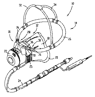
Turning now to the drawings and particularly Fig. 1, respiratory apparatus 10
in accordance with the invention is illustrated. Broadly speaking the
apparatus 10
CA 02315870 2006-08-15
-5-
includes a mask 12 equipped with an inflatable-type harness assembly 14 and a
comfort
adjustment assembly 16 which allows lessening of the engagement force exerted
by the
mask against a user's face_
In more detail, the mask 12 includes a synthetic resin main body 18 presenting
a marginal resilient lip defining a fitting surface 20 adapted to eingage a
user's face in
surrounding relationship to the user's nose and mouth. The mask 12 is also
equipped
with a regulator 22 which is designed to mix incoming pressurized breathable
gas
(usually oxygen) with atmospheric air for delivery of a breathable gas mixture
into the
confines of the mask body 18; the regulator is of the type described in U.S.
Patent No.
5,307,793. A gas line 24 is operatively
coupled to the regulator 22 as shown with the remote end thereof adapted for
coupling
to a conventional gas source_ A harness inflation button 25 is also provided
as a part
of the regulator 22.
The hamess assembly 14 includes an elongated, inflatable, tubular strap
element
26 having a pair of terminal ends 28, 30 operatively coupled to mask 12 as
will be
described. A somewhat U-shaped strap 32 is connected to opposite sides of the
element
26 as shown, and is configured to extend over a wearer's head. A secondary
strap 34
extends from the top of strap 32 and is secured to strap element 26 at a rear
portion
thereof. The strap element 26 is formed of extensible synthetic resin material
and is
selectively inflatable so as to extend and assume an enlarged configuration
allowing
ready fitting of the harness assembly over the user's head. Upon deflation of
the strap
element 26, the latter constricts and comes into tight engagement with the
user's head,
thereby serving to draw the mask 12, and particularly fitting surface 20
thereof, into
tight engagement with the user's face. Strap elements of this type are known,
see, e.g.,
U.S. Patent No_ 4,915,106.
The comfort adjustment assembly 16 includes a pair of elongated, tubular
metallic (aluminum) mounts 36 which extend from regulator 22 as shown, as well
as
a housing assembly 38 (see Figs. 2-4) supported at each terminal end 28,30 of
the strap
element 26. Referring specifically to Figs. 2-4, it will be observed that each
assembly
3 8 includes an elongated, tubular metallic housing 40 presenting opposed,
front and rear
ends 42 and 44, as well as an inwardly extending integral annular stop wall
46. As
shown, a corresponding tubular mount 36 extends coaxially throughout the
length of
housing 40 and into the confines of strap element 26. The forward end of
housing 40
includes an annular Delrin washer or bushing 48 which abuts the forward face
of stop
wall 46. A coil spring 50 engages the face of bushing 48 remote from stop wall
46.
CA 02315870 2000-04-11
WO 99/20349 PCTIUS98/19035
-6-
Three separate, annular brake or stop washers 52 engage the forward end of
spring 50.
As is evident from the drawings, the bushing 48, spring 50 and stop washers 52
each
slidably receive the tubular mount 36. However, the stop washers 52 have
relatively
large central openings therethrough permitting the washers to rock to a
limited degree
on the mount 36 and assume a canted, locking position relative thereto. A pin
54 is
mounted through the sidewall of housing 40 adjacent end 42 and engages the
adjacent
face of the forward most stop washer 52, thus captively retaining, with the
mount 36,
the stop washers 52, spring 50 and bushing 48 between the pin wa1146.
The mid-portion of housing 40 is provided with a fixed Delrin bushing 56
spaced rearwardly from stop wa1146. A resilient annular forward seal 58 is
located
between the wal146 and bushing 56 as shown. The rearward end of housing 40 has
a
Delrin rear seal 60 secured to the housing body. The seal 60 has an enlarged,
irregular
annular relieved zone 62 at the rearward end thereof which houses a
supplemental
resilient annular sea164.
Referring specifically to the mount 36, it will be observed that it includes
an
aperture 66 through the sidewall thereof and moreover has an adjacent relieved
area 68
formed in the outer sidewall thereof. The mount 36 carries a fixed Delrin
bushing 70
rearwardly of the aperture 66 and relieved area 68, with the bushing 70 being
secured
via a coupler 72. An annular resilient rear seal 74 is situated in engagement
with the
forward face of bushing 70, with the front edge of the seal 74 engaging the
forward
shoulder of the relieved area 68. Thus, the bushing 70 and seal 74 are secured
to the
mount 36 and move in unison therewith. As best observed in Fig. 2, a cavity 75
is
defined between the seals 58 and 74.
The terminal ends 28, 30 of the strap element 26 are affixed to the
corresponding
housings 40 by means of a crimp ferrule 76 or other expedient. Thus, the
housing 40
and components coupled thereto are effectively secured to the strap element
26.
An annular adjustment button 78 is slidably secured to the forward end 42 of
housing 40. Specifically, the button 78 includes an annular recess 80
receiving the end
42. The sidewall of the button has a slot 82 therein which accommodates pin
54, thus
defining the movement stroke of the button. The inner annular wa1184 of the
button
slidably receives the mount 36 and presents an annular butt end 86.
The use of the embodiment of Figs. 1-4 proceeds as follows, assuming that the
mask is stored in a ready position, usually in a stowage box adjacent the crew
seating.
As stowed, the respective terminal ends 28, 30 of the strap element 26 are
slidably
mounted on the corresponding mounts 36, and are releasably locked in place via
the
CA 02315870 2000-04-11
WO 99/20349 PCT/US98/19035
-7-
stop washers 52. The user first grasps the mask and pulls it from its stowage
box while
depressing the button 25. This causes pressurized oxygen to flow through the
regulator
and thence through the mounts 36 so as to fully inflate harness 26 so that the
latter
assumes an enlarged position permitting ready donning over the head of the
user (see
Figs. 2-4). At the same time, however, pressurized oxygen flows through
aperture 66
so as to pressurize the cavity 75. This induces movement of housing 40 the
left as
viewed in Fig. 4, and the frictional engagement between the tube 36 and stop
washer
52 moves the latter to their upright release position thereby allowing free
movement of
the housing. In this condition, the assembly 38 assumes the normal position
depicted
in Fig. 2.
Once the mask is donned with the strap element 26 in its inflated condition,
the
user releases the button 25. This causes an immediate deflation of the strap
element 26,
with the oxygen therein flowing back through the tubular mount 36 for
exhaustion to
the atmosphere through regulator 22. During this sequence, the pressurized
oxygen
within chamber 75 is also exhausted via aperture 66. Thus, the strap element
26 and the
cavity 75 are at essentially ambient pressure, with the seals 58 and 74 spaced
apart as
shown in Fig. 2 and with the strap element 26 shifted relative to the mount 36
so that
the latter extends well into the confines of the strap element.
It will be appreciated that in the initially deflated condition, the strap
element
may fit extremely tightly against the head of the user, to the extent that it
may be
uncomfortable. In order to afford a more comfortable wearing, the user may
then
optionally depress the button 78 as best seen in Fig. 4. When this is done,
the butt end
86 of wall 84 comes into contact with the canted stop washers 52, to move
these to a
more orthogonal position relative to the mount 36 out of frictional locking
engagement
with the mount. Further depression of the button 78 serves to compress spring
50 and
translates housing 40 and the terminal end 30 of the strap element 26 along
the length
of the tubular mount 36. This effectively increases the harness size, i.e.,
the relative
distance between the terminal end 30 and fitting surface is changed so as to
lessen the
engagement force exerted by the fitting surface 20 of mask 12 against the
user's face.
It will be appreciated that once the button 78 is released, the spring 50
serves to shift
the button back to its starting position and causes the stop washers 52 to
reassume their
canted, locking position. As a consequence, the effective size of the strap
element 26
can be increased to any desired extent within a preset range, thus permitting
essentially
infinite adjustment of the mask engagement force against the user's face.
CA 02315870 2000-04-11
WO 99/20349 PCT/US98/19035
-8-
It will of course be appreciated that either one or both of the terminal ends
28,
30 of the strap element 26 may be adjusted along the length of the
corresponding
mounts 36. This effectively doubles the range of adjustment afforded by the
apparatus
10. Generally, each terminal end of strap element 26 is translatable along a
correspond-
ing mount 36 through a distance of at least about 1/2 inch, more preferably at
least
about 3/4 inch.
Fig. 3 illustrates the adjustment assembly 16 at its most extended position,
where it will be observed that the aperture 66 is between the seals 58 and 74.
Thus,
upon inflation of the strap element 26 through the medium of regulator 22, the
seal 58
and associated structure is shifted leftwardly as seen in Fig. 3 until the
assembly 38
assumes the normal Fig. 2 position. Thus, no matter what the relative position
of the
strap assemblies 38 may be on the corresponding mounts 36, upon inflation of
the strap
element 26, the assemblies 38 each reset to the same, normal position shown in
Fig. 2.
Fig. 5 illustrates an alternative embodiment in accordance with the invention
making use of a modified housing assembly 88 for each terminal end of the
strap
element 26. As in the case of the embodiment of Figs. 1-4, each assembly 88
includes
a tubular housing 90 which is secured to a terminal end 3 8 of the strap 26,
being affixed
by ferrule 76. The housing 90 includes a forward end 92 and an opposed
rearward end
94. The forward end 92 is externally threaded, and an annular cap 96 is
mounted
between.
The forward end 92 is configured to present an annular relief passageway 98
which communicates with an axial relief passageway 100. An annular metallic
bushing
102 is supported adjacent passageway 98 and abuts an annular, cup-shaped seal
retainer
104. A small clearance is provided between the rearward face of bushing 102
and
passageway 98. A resilient annular sea1106 is seated within retainer 104, and
engages
mount 36. The passageway 100 communicates with a cavity or zone 108 between
cap
96 and the forward butt end 109 of housing 90. An 0 ring I 10 is seated
against the butt
end 109 in surrounding relationship to the passageway 100. An annular bushing
112
engages 0-ring 110 and butt end 109 as illustrated. A spring 114 is situated
within zone
108 between cap 96 and bushing 112. The engagement force of spring 114 against
bushing 112 serves to compress 0 ring 110 and form a seal, normally preventing
escape
of gas through passageway 100. An oxygen escape opening (not shown) is
provided
through a wall of cap 96 in communication with zone 108.
The rearward end of housing 90 is equipped with a seal 116 similar to the seal
62 described previously; the sea1116 carries an annular resilient inner
sealing ring 118
CA 02315870 2000-04-11
WO 99/20349 P(,'T/US98/19035
-9-
as shown which engages mount 36. A bushing unit 120 is affixed to element 36
and
supports a resilient annular near seal 122. The latter is maintained in place
by
engagement with the forward shoulder of relieved area 124 provided on the
mount 36.
An aperture 126 is provided through the wall of mount 36 at area 124. A cavity
128 is
thus formed between the seal 122 and the forward end 92 of housing 90.
The use of the Fig. 5 embodiment proceeds in its initial stages exactly as
described with reference to the first embodiment. That is, the user grasps the
mask
body and depresses button 25 thereby causing pressurized oxygen to flow
through the
mount 36 for expansion of strap element 26. At the same time, such pressurized
oxygen
is delivered via aperture 126 so as to pressurize cavity 128. This moves
housing 90 and
the terminal end 38 of strap element 26 leftwardly as shown in Fig. 5 until
the pressure
within cavity 128 exceeds a predetermined maximum set by the engagement force
of
spring 114 against bushing 112 and 0 ring 110. When this maximum pressure is
exceeded, oxygen begins to escape through passageway 100 and to the atmosphere
via
the cap escape opening. This in turn prevents further movement of the housing
90 and
terminal end 38 relative to the mount 36. Upon deflation of the strap element
26, the
cavity 128 remains pressurized.
During use of the respiration assembly of Fig. 5, the cavity 128 remains
pressurized and maintains the comfort position for the mask. It will be
appreciated that
once the spring engagement force for the assembly 88 is set, the Fig. 5
embodiment is
not further adjustable.
It will be appreciated that the comfort control apparatus of both of the above
embodiments indefinitely maintains a comfortable engagement force between the
fitting
surface 20 of mask 12 and the user's face, while the strap element 26 is fully
deflated.
Thus, leakage from strap 26 is not a factor in maintaining comfort control.
When the user wishes to remove the respiratory apparatus 10, the button 25 is
again depressed to fully inflate the strap element 26 allowing the apparatus
10 to be
easily removed. At this point the strap element 26 is again deflated and is
ready for
stowage.