Note : Les descriptions sont présentées dans la langue officielle dans laquelle elles ont été soumises.
CA 02316448 2000-08-18
A VALVE MOVEMENT CONTROL SYSTEM OF AN INTERNAL COMBUSTION ENGINE
BACKGROUND OF THE INVENTION
The present invention relates to a valve movement control
system of an internal combustion engine having a hydraulic
operational characteristic variable mechanism for altering
operational characteristic such as opening-closing time of an
engine valve, including a hydraulic phase variable mechanism
for altering opening-closing time of an engine valve such as
a suction valve or an exhaust valve.
Hitherto, there has been known a valve movement control
system of an internal combustion engine having a hydraulic phase
variable mechanism which alters opening-closing time of a
suction valve or an exhaust valve by altering relative phase
of a camshaft to a crankshaft in accordance with operational
state of the engine, in order to improve engine output and fuel
consumption.
For example, in a valve timing control system of an
internal combustion engine disclosed in Japanese Laid-Open
Patent Publication Hei 11-173119, a valve timing adjusting
mechanism provided on an end of a suction side camshaft has a
rotor housing drivingly connected to a crankshaft and a vane
rotor having a plurality of vanes drivingly connected to the
suction side camshaft. On both sides of the each vane are formed
a retard chamber and an advance chamber respectively, and
charging and discharging of operating oil to the retard chamber
and the advance chamber are controlled by a OCV (oil control
valve) operated based on operational state of the engine, so
that relative phase of the suction side camshaft to the
crankshaft is altered to adjust opening-closing timing of the
suction valve.
The operating oil supplied by an oil pump driven by the
engine and controlled by the OCV is charged to or discharged
from the retard chamber and the advance chamber, passing through
a head oil passage provided in a cylinder head, an annular oil
groove provided on an inner peripheral surface of a journal
1
CA 02316448 2000-08-18
bearing formed by the cylinder head and a bearing cap for
supporting the camshaft, and an oil passage provided in the
camshaft.
Generally, a minute gap exists between the camshaft and
the journal bearing. Therefore, in the prior art, when the
engine is stopped to stop the oil pump and the operating oil
is not supplied to the oil passage, the operating oil in the
oil passage provided in the suction side camshaft and the
operating oil in the retard chamber and the advance chamber flow
out through the minute gap as time goes by, though by very small
amount , so that the operating oil in the oil passage , the retard
chamber and the advance chamber has a tendency to decrease.
When the engine is started from the state that operating
oil in the oil passage, the retard chamber and the advance
chamber is reduced, some waiting time is required after the
engine is started to drive the oil pump, for filling the oil
passage and the retard chamber or the advance chamber with the
operating oil (whether any one chamber or both chambers must
be filled with the operating oil depends on setting of the valve
timing adjusting mechanism during the engine is stopped) , and
enabling the valve timing adjusting mechanism to operate.
However, a time required for the engine to reach a loaded
operation necessitating valve timing adjustment is relatively
long in general and the oil passage and the retard chamber or
the advance chamber can be filled with the operating oil during
the time, therefore the above-mentioned required waiting time
does not came into question.
However, on re-starting of the engine when the engine
is started from a state that warming-up is completed, the time
required for the engine to reach the loaded operation is
relatively short in general, so that sometimes the oil passage
and the retard chamber or the advance chamber are not filled
with the operating oil before the engine reaches the loaded
operation. In this case, the valve timing adjusting mechanism
can not operate until the oil passage and the retard chamber
or the advance chamber are filled with the operating oil. This
2
CA 02316448 2000-08-18
late operation causes lowering of the engine output, and
lowering of drive-ability in case of an engine mounted on a
vehicle.
SUMMARY OF THE INVENTION
The present invention has been accomplished in view of
the foregoing, and an object of the invention is to provide a
hydraulic operational characteristic variable mechanism with
no operational lag or a shortened operational lag on re-starting
of the engine. Another object of the invention is to provide
a structure facilitating preparation of a operating oil reserve
chamber.
The present invention provides a valve movement control
system of an internal combustion engine, comprising a camshaft
driven by a crankshaft having a cam journal supported for
rotation by a support member; a hydraulic operational
characteristic variable mechanism provided on the camshaft for
altering operational characteristic of an engine valve driven
by a cam of the camshaft; an operating oil passage extending
from an oil pressure supply source driven by the internal
combustion engine to the operational characteristic variable
mechanism passing through a plurality of members including at
least the camshaft and the support member; and an oil pressure
control valve provided in the operating oil passage for
controlling pressure of operating oil sent to the operating
characteristic variable mechanism. The operating oil passage
forms a control oil passage having a first oil passage and a
second oil passage between an operation chamber of the
operational variable mechanism and the oil pressure control
valve, the first oil passage provided in the camshaft has an
end communicating with the operation chamber and another end
communicating with the second oil passage formed between the
cam journal and the support member. In such a valve movement
control system, an operating oil reserve chamber communicating
with the control oil passage is provided above the cam journal.
According to this invention, since the operating oil
3
CA 02316448 2000-08-18
reserve chamber is provided above the cam journal and there is
a greater quantity of the operating oil above the minute gap
between the cam journal and the support member in comparison
with the prior art , even if the operating oil flows out through
the minute gap during the engine is stopped, the oil pressure
supply source is not driven and the operating oil is not supplied
to the operation chamber of the operational characteristic
variable mechanism and the control oil passage, a time required
for the operating oil in the operation chamber and the first
and second oil passages to decrease to the same extent as the
prior art can be prolonged
As the result , a possibility that the operation chamber
and the first and second oil passages are filled with the
operating oil or relatively large quantity of the operating oil
remains in the operation chamber and the first and second oil
passages upon re-starting such as starting after idle stop can
be raised, by setting a quantity of the operating oil reserved
in the operating oil reserve chamber suitably. Therefore,
there is no operation lag or operation lag time is shortened,
so that the engine can be operated by the engine valve of a
desired operational characteristic relatively soon and output
lowering caused by non-operation of the operational
characteristic variable mechanism can be prevented with a high
possibility.
In such a valve movement control system of an internal
combustion engine, the support member may comprise a lower
member and a cam holder disposed above the lower member, and
the operating oil reserve chamber may be provided in the cam
holder and may communicate with the second oil passage within
the cam holder.
According to this valve movement control system, the
operating oil reserve chamber can be provided utilizing the cam
holder disposed above the lower member to support the cam
journal from the upside. Therefore, there is no necessity to
dispose an additional member for forming the operating oil
reserve chamber above the cam journal. Moreover, it is possible
4
CA 02316448 2000-08-18
to provide an operating oil reserve chamber in a customary
engine having a phase variable mechanism easily only by changing
the cam holder and without changing arrangement of parts around
the camshaf t .
Since the second oil passage constituting the control
oil passage is provided in the cam holder constituting the
support member, the operating oil reserve chamber can be
connected with the control oil passage compactly and easily,
without necessitating an additional connection passage, by
connecting the operating oil reserve chamber with the second
oil passage within the cam holder.
BRIEF DESCRIPTION OF THE DRAWINGS
Fig. 1 is a schematic whole view of an internal combustion
engine applied with the present invention;
Fig. 2 is a sectional front view of Fig. 1;
Fig. 3 is a sectional view taken along the line III-
I I I of Fig . 2 ;
Fig. 4 is a sectional view taken along the line IV-IV
of Fig. 2;
Fig . 5 is a schematic view of oil passages of the valve
movement control system; and
Fig. 6 is a partial sectional view of an oil pressure
control valve.
DETAILED DESCRIPTION OF THE PREFERRED EMBODIMENT
Hereinafter, a preferred embodiment of the present
invention will be described with reference to Figs. 1 to 6.
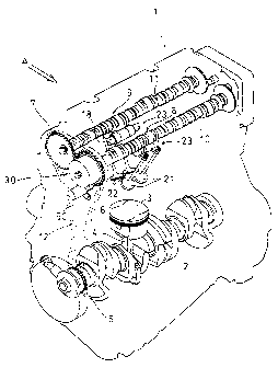
In this embodiment , the internal combustion engine 1 is
a spark-ignition DOHC type four cylinders internal combustion
engine mounted on a vehicle with a crankshaft directed in
right-left direction of the vehicle. As shown in Fig. 1, a
piston 3 fitted slidingly in a bore of a cylinder is connected
to the crankshaft 2 by means of a connecting rod 4. A drive
sprocket 5 is provided at a right end ( left end in Fig. 1 ) portion
of the crankshaft 2 and a suction cam sprocket 6 and an exhaust
CA 02316448 2000-08-18
cam sprocket 7 are provided at respective right end portions
of a suction camshaft 10 and an exhaust camshaft 7 which are
disposed in parallel with each other. The suction camshaft 10
and the exhaust camshaft 7 are provided with a suction cam 8
and an exhaust cam 9 respectively. A timing chain 12 is wound
round the sprockets 5, 6, 7 so that camshafts 10, 11 are driven
by the crankshaft 2 so as to rotate with a sped reduction ratio
of 1 / 2 . As shown in Fig . 2 , the sprockets 5 , 6 , 7 and the timing
chain 12 are housed in a chain chamber 16 formed by a cylinder
head cover 14 , an oil pan and a chain cover 15 attached to right
sides of a cylinder head 13 and a cylinder block.
In this description, "front" , "rear" , "right" and "left"
are expressed with respect to one who looks toward the front
of the vehicle with the engine mounted riding on the vehicle.
In Fig. 1, the arrow A shows traveling direction of the vehicle.
And upside and downside mean those with respect to the internal
combustion engine 1 mounted on the vehicle.
Referring to Fig. 3 too, a plurality of rocker shaft
holders is put on the cylinder head 13 at both ends of the row
of cylinders and between the neighboring cylinders. In each
of the rocker shaft holders is fixed a suction rocker shaft 17
and an exhaust rocker shaft 18 which extend in front-rear
direction in parallel with each other and support for rocking
motion a suction rocker arm and an exhaust rocker arm
respectively. On the each rocker shaft holder is put a
corresponding cam holder. In the drawings, a rocker shaft
holder 19 at the right end and a cam holder 20 at the right end
are shown. Each pair of the rocker shaft holder and the cam
holder is fixed to the cylinder head 13 by bolts.
In order to support the suction and exhaust camshafts
, 11 so as to rotate relatively to the cylinder head 13 , cam
journals of the both camshafts 10, 11 are supported in circular
holes each having a lower support surface formed by a semi-
cylindrical hollow on an upper surface of the rocker shaft
holder and an upper support surface formed by a semi-cylindrical
hollow on a lower surface of the cam holder . In the drawings ,
6
CA 02316448 2000-08-18
cam journals 10a, lla at the right end, a lower support surface
19a of a rocker shaft holder 19 at the right end and an upper
support surface 20a of a cam holder 20 at the right end are shown.
The rocker shaft holders and the cam holders constitute support
members for the cam journals, and the rocker shaft holders
constitute lower members of the support members.
Each cylinder has a pair of suction valves ( engine valves )
21 driven by the suction rocker arm and a pair of exhaust valves
( engine valves ) 22 driven by the exhaust rocker arm. Between
the suction camshaft 10 and the suction valve 21 and between
the exhaust camshaft 11 and the exhaust valve 22, there are
provided respective changing mechanisms 23 which change lift
and opening time of the valves in accordance with engine
rotational speed.
On a right end portion of the suction camshaft 10 having
the suction cam sprocket 6 is provided a phase variable
mechanism 30, which is a hydraulic operational characteristic
variable mechanism for altering relative phase of the suction
camshaft 10 or the suction cam to the crankshaft 2 to advance
or retard opening-closing time of the suction valve 21.
The construction of the phase variable mechanism 30
provided on the right end portion of the suction camshaft 10
will be described with reference to Figs . 2 and 4 . In Fig . 2 ,
a part of the suction camshaft 10 is shown by a section other
than that of the other part for the convenience of the
description.
A cylindrical boss member 31 is connected to the suction
camshaft 10 by a pin 32 and a bolt 33 in a state that a support
hole 31a formed at the center of the boss member 31 is coaxially
fitted to the right end portion of the suction camshaft 10. The
boss member 31 constitutes a camshaft side member drivingly
connected to the suction camshaft 10 so as to rotate as one body.
The suction cam sprocket 6 is formed in a cup-like shape
having a circular hollow 6a and sprocket teeth 6b are formed
on a periphery of the sprocket 6. An annular housing 34 fitted
in the hollow 6a of the suction cam sprocket 6 and a plate 35
7
CA 02316448 2000-08-18
piled on the housing 34 axially are connected to the suction
cam sprocket 6 by four bolts 6 penetrating them so as to
constitute a crankshaft side member drivingly connected to the
camshaft 2 through the timing chain 12.
The boss member 31 is enclosed in a space surrounded by
the housing 34 and the plate 35 so as to rotate relatively to
the housing 34. The boss member 31 has a pin hole penetrating
it axially in which a lock pin 37 is fitted so as to slide. The
lock pin 37 is forced toward a lock hole 6c formed in the suction
cam sprocket 6 by a spring 38 inserted between the lock pin 37
and the plate 35 in a compressed state.
Within the housing 34, four fan-shaped hollows 34a are
formed around axis of the suction camshaft 10 at intervals of
90 degrees, and four vanes 31b radially projecting from an outer
periphery of the boss member 31 are fitted in the respective
hollows 34a so as to rotate about the axis of the boss member
31 by 30 degrees relatively to the hollows 34a. Four seal
members 39 provided at respective tip ends of the vanes 31b make
sliding contact with bottom walls of the hollows 34a, and four
seal members 40 provided on an inner peripheral surface of the
housing 34 make sliding contact with an outer peripheral surface
of the boss member 31, so that a retard chamber 41 and an advance
chamber 42 , which are operation chambers of the phase variable
mechanism 30, are formed on both sides of each vane 31b
respectively.
In a right end portion of the suction camshaft 10 are
formed a pair of oil passages 43 and a pair of oil passages 44
in parallel with axis of the suction camshaft 10. These oil
passages 43, 44 have respective openings 43a, 44a on an outer
periphery of the cam journal l0a at the right end. The oil
passages 43 communicate with the retard chambers 41 through oil
passages 45 including annular grooves formed on an outer
periphery of the suction camshaft 10 and oil passages 47
radially penetrating the boss member 31, and the oil passages
44 communicate with the advance chambers 42 through oil passages
46 including annular grooves formed on an outer periphery of
8
CA 02316448 2000-08-18
the suction camshaft 10 and oil passages 48 radially penetrating
the boss member 31. The lock hole 6c for fitting to the lock
pin 37 communicates with any one of the advance chambers 42
through a not shown oil passage.
When the advance chamber 42 is not supplied with the
operating oil, the lock pin 37 is fitted in the lock hole 6c
of the suction cam sprocket 6 by force of the spring 38, so that
the suction camshaft 10 is locked in a most retarded state that
the suction camshaft 10 is rotated counterclockwise relatively
to the suction cam sprocket 6. Then, if the advance chamber
42 is supplied with the operating oil to raise oil pressure in
the chamber 42 gradually, the lock pin 37 escapes from the lock
hole 6c by the oil pressure in the advance chamber 42 against
the spring 38, the suction camshaft 10 rotates clockwise
relatively to the suction cam sprocket 6 by difference of
pressures acting on both sides of the vane 31, relative phase
of the suction camshaft 10 to the crankshaft 2 alters in an
advancing direction, phase of the suction cam 8 relative to the
crankshaft 2 also advances, and opening time and closing time
of the suction valve 21 change toward advancing side. Thus,
opening-closing time of the suction valve 21 can be changed
continuously by controlling oil pressure in the retard chamber
41 and the advance chamber 42.
Next, operating oil passages of the valve movement
control system will be described with reference to Fig. 5.
Oil pumped up by an oil pump 50 driven by the crankshaft
2 from an oil pan 51 through an oil passage 52 is discharged
as lubricant oil of neighborhood of the crankshaft 2 and the
valve movement mechanism, and as operating oil of the phase
variable mechanism 30 and the changing mechanism 23.
The operating oil passage through which the oil
discharged from the oil pump 50 passes , includes a supply oil
passage leading to the oil pressure control valve 60 and the
oil pressure changing valve 58 from the oil pump 50, a control
oil passage 55 and a changing oil passage 57. And the supply
oil passage includes a common supply oil passage 53 , a supply
9
CA 02316448 2000-08-18
oil passage for phase 54 and a supply oil passage for change
56.
From the common supply oil passage 13 formed through the
cylinder block and the cylinder head 13 branches the supply oil
passage for phase 54 leading to the oil pressure control valve
60 which controls oil pressure of the retard chamber 41 and the
advance chamber 42. To the oil pressure control valve 60 is
connected the control oil passage 55 leading to the phase
variable mechanism 30. Further, the supply oil passage for
change 56 leading to the oil pressure changing valve 58 is
connected to the common supply oil passage 53 branching from
the passage 53. To the oil pressure changing valve 58 is
connected the changing oil passage 57 leading to the changing
mechanism 23.
Signals from various engine operational state detecting
means, such as a suction camshaft sensor detecting a rotational
position OI of the suction camshaft 10, a TDC sensor detecting
a top dead center OTD of the piston 3 based on an exhaust camshaft
sensor detecting a rotational position of the exhaust camshaft
11, a crankshaft sensor detecting a rotational position UC of
the crankshaft 2, a suction negative pressure sensor detecting
suction negative pressure P, a cooling water temperature sensor
detecting cooling water temperature TW, a throttle opening
degree sensor detecting throttle opening degree O TH and a
rotational speed sensor detecting rotational speed Ne of the
engine 1, are inputted into an electronic control unit 59.
More detailed construction of the oil passages and the
oil pressure control valve 60 will be described with reference
to Figs. 2, 3 and 6.
As shown in Fig. 3, the common supply oil passage 53 is
formed in the right end portion of the cylinder head 13 extending
upward from a contact surface to the cylinder block. The supply
oil passage 56 branches from the common supply oil passage 53
at right angles to the passage 56 and communicates with the oil
pressure changing valve 58.
The oil pressure changing valve 58 which acts in
CA 02316448 2000-08-18
accordance with instructions from the electronic control unit
59, has a normal-close-type solenoid valve 58a and changes
pressure of operating oil in the changing oil passage 57 in
accordance with engine rotational speed into a low pressure or
a high pressure to operate the changing mechanism 23.
The supply oil passage for phase 54 is connected to the
common supply oil passage 53 at a downstream position of the
supply oil passage for change 56. The supply oil passage 54
includes an oil passage section 54a which extends from the
common supply oil passage 53 at right angles and opens on an
attachment surface provided on a front surface 13a of the
cylinder head 13 , an oil passage section 54b formed in a cover
24 attached on the attachment surface, and an oil passage
section 54c extending in parallel with the oil passage section
54a to reach the oil pressure control valve 60.
The oil pressure control valve 60, which is inserted in
an insertion hole 13b drilled from a right end surface of the
cylinder head 13 at inside of the looped timing chain 12,
comprises a cylindrical sleeve 61, a spool 62 fitted for sliding
in the sleeve 61, a duty solenoid 63 fixed to the sleeve 61 for
driving the spool 62 , and a spring 64 forcing the spool 62 toward
the duty solenoid 63. Electric current to be supplied to the
duty solenoid 63 is duty controlled by ON duty in accordance
with instructions from the electronic control unit 59 so that
axial position of the spool 62 is changed continuously against
the spring 64.
The sleeve 61 has an inlet port 61a positioned at the
center communicating with the supply oil passage for phase 54 ,
a retard port 61b and an advance port 61c provided on both sides
of the inlet port 61a respectively, and drain ports 61d, 61e
formed outside of the ports 61b, 61c respectively. On the one
hand, the spool 62 has a central groove 62a, lands 62b, 62c
provided on both sides of the groove 62a respectively, and
grooves 62d, 62e provided outside of the lands 62b, 62c
respectively. A tip end portion of the sleeve 61 provided with
the drain port 61e penetrates the insertion hole 13b to project
11
CA 02316448 2000-08-18
into a space formed in the cylinder head 13. The drain port
61d communicates with the drain oil passage 49.
In Fig. 6, the spool 62 is positioned at a neutral position
and duty ratio of the duty solenoid 63 is set at 50~ for example.
If the duty ratio is increased, the spool 62 is moved to the
right in Fig. 6 from the neutral position against the spring
64, the inlet port 61a communicates with the advance port 61
through the groove 62a, and the retard port 61b communicates
with the drain port 61d through the groove 62d. As the result ,
the advance chamber 42 of the phase variable mechanism 30 is
supplied with operating oil, the suction camshaft 10 rotates
clockwise relatively to the suction cam sprocket 6 in Fig. 4,
and phase of the suction camshaft 10 changes continuously toward
advancing side. Then, duty ratio of the duty solenoid 63 is
set at 50~ when a target relative phase is obtained. The spool
62 is held again at the neutral position where the inlet port
61a is closed between the lands 26b, 26c, and the retard port
61b and the advance port 61c are held at positions closed by
the lands 62b, 62c respectively. Thus, the suction cam sprocket
6 and the suction camshaft 10 are integrated to maintain the
relative phase constant.
In order to change relative phase of the suction camshaft
continuously toward retard side, duty ratio of the duty
solenoid 63 is decreased from 50$. In this case, the spool 62
is moved from the neutral position to the left in Fig. 6, the
inlet port 61a communicates with the retard port 61b through
the groove 62a, the advance port 61c communicates with the drain
port 61e through the groove 62e, and the retard chamber 41 of
the phase variable mechanism 30 is supplied with operating oil.
Then duty ratio of the duty solenoid 63 is set at 50~ when a
target relative phase is obtained. The spool 62 is held again
at the neutral position shown in Fig. 6 to maintain a constant
relative phase.
The control oil passage 55 (Fig. 5) includes a retard
side control oil passage 70 and an advance side control oil
passage 71 as shown in Figs . 2 and 3 . The retard side control
12
CA 02316448 2000-08-18
oil passage 70 includes an oil passage 70a extending upward from
the retard port 61b within the cylinder head 13 and the rocker
shaft holder 19 , an oil passage 70b formed on a contact surface
of the rocker shaft holder 19 to the cam holder 20 to communicate
with the oil passage 70a, an oil passage 70c communicating with
the oil passage 70b and extending along an outer periphery of
the cam journal l0a of the suction camshaft 10 which is formed
by a semi-annular groove on the lower surface 19a of the rocker
shaft holder 19, an oil passage 70d communicating with the oil
passages 70b, 70c and integrally joined with a retard side
operating oil reserve chamber 72 which opens on the upper
support surface 20a of the cam holder 20 and a contact surface
of the cam holder 20 to the rocker shaft holder 19, the
aforementioned oil passage 43 communicating with the oil
passage 70d through the opening 43a, and the aforementioned oil
passage 45.
On the one hand, the advance side control oil passage
71 includes an oil passage 71a extending upward from the advance
port 61c within the cylinder head 13 and the rocker shaft holder
19 , an oil passage 71b formed on a contact surface of the rocker
shaft holder 19 to the cam holder 20 to communicate with the
oil passage 71a ( Fig . 3 ) , an oil passage 71c communicating with
the oil passage 71b and extending along an outer periphery of
the cam journal l0a of the suction camshaft 10 which is formed
by a semi-annular groove on the lower support surface 19a of
the rocker shaft holder 19, an oil passage 71d communicating
with the oil passages 71b, 71c and integrally joined with an
advance side operating oil reserve chamber 73 which opens on
the upper support surface 20a of the cam holder 20 and a contact
surface of the cam holder 20 to the rocker shaft holder 19, the
aforementioned oil passage 44 communicating with the oil
passage 71d through the opening 44a, and the aforementioned oil
passage 46. The oil passage 71b of the advance side control
oil passage 71 corresponds to the oil passage 70b of the retard
side control oil passage 70.
Therefore, the retard side control oil passage 70 and
13
CA 02316448 2000-08-18
the advance side control oil passage 71 constitute operating
oil passages formed through a plurality of members including
the cylinder head 13 , the rocker shaft holder 19 , the cam holder
20 and the suction camshaft 10.
The operating oil reserve chambers 72, 73 are composed
of deep cuts formed in the cam holder 20 which include the oil
passages 70d, 71d as a whole. As mentioned above, the oil
passages 70d, 71d are semi-annular oil passages to be formed
on the upper support surface 20a of the cam holder 20 in order
to connect the openings 43a, 44a of the oil passages 43, 44 formed
in the suction camshaft 10 with the oil passages 70b, 71b. The
oil passages 70d, 71d have the same depth as that of the oil
passages 70c, 71c as shown in Figs. 2 and 3 by a two-dots-and-dash
line . The deep cuts are formed simultaneously with casting of
the cam holder 20.
Upper surfaces 72a, 73a of the operating oil reserve
chambers 72, 73 are positioned higher by a predetermined
distance A than the cam journal l0a (Fig. 3). Further, when
the retard chamber 41 and the advance chamber 42 of the phase
variable mechanism 30 are in their highest position, height of
the uppermost portion of the chambers 41, 42 is the same as height
of the upper surfaces 72a, 73a. Width of the operating oil
reserve chambers 72, 73 in the direction of axis of the suction
camshaft 10 is the same as that of the oil passages 70c, 71c.
Rear ends of the operating oil reserve chambers 72, 73 are
positioned at substantially the same positions as rear ends of
the oil passages 70b, 71b and at the middle of the suction
camshaft 10 and the exhaust camshaft 11.
The distant A between the upper surface 72a (73a) and
the uppermost portion of the cam journal l0a is decided
depending on a volume of an upper part of the operating oil
reserve chamber 72 (73) existing above the uppermost portion
of the cam journal 10a. The volume of the upper part is decided
so that even if operating oil flows out through the
aforementioned minute gap during a set time set in consideration
of a statistically most feasible time elapsing while the engine
14
CA 02316448 2000-08-18
1 is once stopped then re-started, the oil passage 43 ( 44 ) in
the suction camshaft 10 is filled with operating oil still.
During operation of the engine 1, the phase variable
mechanism 30 is finely controlled by the oil pressure control
valve 60 which acts corresponding to the engine operational
condition. Therefore, the retard side control oil passage 70
and the advance side control oil passage 71 are scarcely closed
for a long time. Accordingly, amount of operating oil flowing
out through the minute gap when relative phase of the suction
camshaft 10 is kept at a target phase is little compared with
the amount of operating oil flowing out when the engine 1 is
stopped, and also the flowing out of operating oil when a
relative phase of the suction camshaft 10 is kept, can be dealt
with by the above-mentioned set time.
It is desirable that the upper surfaces 72a, 73a of the
operating oil reserve chambers 72 , 73 are positioned higher than
the uppermost position of the retard chamber 41 or the advance
chamber 42 as far as the chambers 72, 73 are enclosed in the
cylinder head cover 14 , because the retard chamber 41 and the
advance chamber 42 , which are sometimes positioned higher than
the oil passages 43 , 44 , can be maintained in a state that they
are filled with operating oil during a long time when the engine
1 is stopped, so that the phase variable mechanism 30 can operate
with no operation lag more frequently.
In the above-mentioned embodiment , when the engine 1 is
stopped and therefore the oil pump 50 is stopped, volume of the
retard chamber 41 is maximum while volume of the advance chamber
42 is substantially zero and the lock pin 37 is fitted in the
lock hole 6c of the suction cam sprocket 6 to hold the phase
variable mechanism 30 in the most retarded position. As for
the oil pressure control valve 60, the spool 62 is forced by
the spring 64 so that the inlet port 61a communicates with the
retard port 61b and the advance port 61c communicates with the
drain port 61c.
Now, suppose that a long time has elapsed after the engine
1 was stopped so that substantially no operating oil exists in
CA 02316448 2000-08-18
the retard side control oil passage 70, the advance side control
oil passage 71 and the advance chamber 42.
When this engine 1 of cold condition is started and
becomes cranking state, the oil pump 50 is operated and
delivered oil is sent to the oil pressure control valve 60
through the common supply oil passage 53 as operating oil.
On starting, since the target phase is set at zero, that
is , the most retarded condition, the oil pressure control valve
60 maintains a state at a time when the engine is stopped in
accordance with an instruction from the electronic control unit
59. At this time, the retard chamber 41 communicating with the
inlet port 61a is filled with operating oil through the retard
side control oil passage 70, and substantially at the same time,
the retard side operating oil reserve chamber 72 is also filled
with operating oil . On the one hand, substantially no operating
oil exists in the advance chamber 42. And this state is
maintained also when starting of the engine 1 has been completed
and the engine becomes idling state.
When the engine 1 shifts to a loaded operation thereafter,
duty ratio of the duty solenoid 63 is controlled by instructions
from the electronic control unit 59 so that phase of the suction
cam 8 becomes equal to a target phase set in accordance with
the engine load and the engine rotational speed. Therefore,
the spool 62 is moved so that the inlet port 61a communicates
with the advance port 61c, the advance chamber 42 is filled with
operation oil through the advance side control oil passage 71,
and substantially at the same time, the advance side operating
oil reserve chamber 73 is also filled with operating oil.
When oil pressure in the advance chamber 42 exceeds a
predetermined value, the lock pin 37 is separated from the lock
hole 6c by the oil pressure to enable the phase variable
mechanism 30 to operate, and the suction camshaft 10 rotates
relatively to the suction cam sprocket 6 to change phase of the
suction camshaft 10 toward advance side. When a target phase
is obtained, duty ratio of the duty solenoid 63 is set at 50~
and spool 62 is positioned at the neutral position.
16
CA 02316448 2000-08-18
Then, duty ratio of the duty solenoid 63 is controlled
by instructions from the electronic control unit 59 so that
relative phase of the suction camshaft 10 becomes equal to a
target phase set in accordance with an engine load and an engine
rotational speed at that time. Accordingly, the spool 62 is
moved right or left from the neutral position to control supply
of operating oil to one of the retard side control oil passage
70 and the advance side control oil passage 71 and drainage of
operating oil from another oil passage. Thus, oil pressure of
the retard chamber 41 and the advance chamber 42 is controlled
to change phase of the suction camshaft 10 continuously. When
the target phase is obtained, duty ratio of the duty solenoid
63 is set at 50~ to hold the spool 62 of the oil pressure control
valve 60 at the neutral position, thus the control oil passage
55 composed of the retard side control oil passage 70 and the
advance side control oil passage 71 is closed and relative phase
of the suction camshaft 10 is held constant.
If the engine 1 is once stopped for idling stop or the
like, the inlet port 61a communicates with the retard port 61a
and the advance port 61c communicates with the drain port 61e
in the oil pressure control valve 60, while the retard chamber
41 is filled with operating oil to the maximum volume and volume
of the advance chamber 42 becomes zero in the phase variable
mechanism 30. At this time, since also the oil pump 50 is
stopped, operating oil is not supplied to the retard side
control oil passage 70, the advance side control passage 71,
the retard chamber 41 and the advance chamber 42. On the one
hand, a little operating oil flows out through the minute gap
formed among the cam journal 10a, the rocker shaft holder 19
and the cam holder 20.
However, because the retard side operating oil reserve
chamber 72 is provided above the cam journal 10a, quntity of
operating oil reserved above the minute gap is larger than that
in the prior art. Therefore, a time required for operating oil
in the retard chamber 41, the oil passage 43 and the oil passage
70d to decrease to the same degree as the prior art can be
17
CA 02316448 2000-08-18
prolonged.
Therefore, when the engine 1 is started again, the retard
chamber 41, the oil passage 43 and the oil passage 70d is filled
with operating oil or more operating oil remains in the retard
chamber 41, the oil passage 43 and the oil passage 72d compared
with the prior art , so that operation lag of the phase variable
mechanism 30 does not occur, or the suction valve 21 becomes
a desired relative phase ( a target phase ) with relatively short
operation lag time, to prevent lowering of output owing to
operation lag of the phase variable mechanism 30.
As aforesaid, when the target phase is obtained, the spool
62 of the oil control valve 60 takes the neutral position to
close the retard side control oil passage 70 and the advance
side control oil passage 71 and hold the relative phase constant .
Also in this case, the retard side control oil passage 70, the
advance side control oil passage 71, the retard chamber 41 and
the advance chamber 42 are not supplied with operating oil. At
this time, owing to torque fluctuation of the suction camshaft
caused by forces given by the suction valve 21, the boss member
31 of the phase variable mechanism 30 compresses operating oil
in the retard chamber 41 and the advance chamber 42 repeatedly,
and a little operating oil flows out from the minute gap through
the oil passages 43, 44 and the oil passages 70c, 70d, 71c, 71d.
Operating oil in the oil passages 43, 44 and the oil
passages 70c, 70d, 71c, 71d is reduced gradually owing to
flowing out of the operating oil through the above-mentioned
minute gap, and at last, air is inhaled in the passages when
the retard chamber 41 and the advance chamber 42 are expanded
by the torque of the suction camshaft 10 based on forces given
by the suction valve 21. However, because a large amount of
operating oil is reserved in the retard side and advance side
reserve chambers 72, 73 above the cam journal 10a, operating
oil flowing out of the oil passages 43, 44 and the oil passages
70c, 70d, 71c, 71d is supplemented by the operating oil in the
operating oil reserve chambers 72, 73. Accordingly, it takes
much time for the air to be inhaled through the minute gap.
18
CA 02316448 2000-08-18
Thus, a possibility that air is inhaled in the oil
passages 43, 44 and the oil passages 70c, 70d, 71c, 71d or the
air further reaches the retard chamber 41 and the advance
chamber 42 of the phase variable mechanism 30 while relative
phase of the suction camshaft 10 is held to a target phase, can
be lowered, so that a phenomenon that phase of the suction
camshaft 10 deviates to the retard side and the advance side
alternately synchronizing with the torque fluctuation of the
suction camshaft 10 does not occur and fluctuation and lowering
of the engine output can be prevented more frequently.
Since the operating oil reserve chambers 72, 73 can be
provided utilizing the cam holder 20 disposed on an upper
portion of the rocker shaft holder 19 for supporting the cam
journal l0a from above, it is unnecessary to provide an
additional member for forming the operating oil reserve chamber
above the cam journal 10a, and the operating oil reserve
chambers 72 , 73 can be provided easily in a customary internal
combustion engine with a phase variable mechanism only by
changing the cam holder without changing arrangement of members
around the suction and exhaust camshafts.
Since the oil passages 70d, 71d constituting the retard
side and advance side control oil passages 70, 71 are provided
in the cam holder, the operating oil reserve chambers 72, 73
can be connected with the retard side and advance side control
oil passages 70, 71 by connecting the operating oil reserve
chambers 72 , 73 with the oil passages 70d, 71d within the cam
holder 20, without necessitating additional connecting
passages, compactly and easily.
Since the operating oil reserve chambers 72, 73 and the
oil passages 70d, 71d can be formed concurrently with casting
of the cam holder 20 , the working man-hour and the cost can be
reduced. Further, the operating oil reserve chambers 72, 73
are formed as deep cuts including the oil passages 70d, 71d
integrally, no construction for connecting the operating oil
reserve chambers 72, 73 with the oil passages 70d, 71d is
necessary to facilitate formation of the operating oil reserve
19
CA 02316448 2000-08-18
chambers 72, 73 and the oil passages 70d, 71d.
In the above-mentioned embodiment, the phase variable
mechanism 30 is provided on the suction camshaft 10 only. But
the phase variable mechanism 30 may be provided on the exhaust
camshaft 11 only or may be provided on both the suction camshaft
and the exhaust camshaft 11. Further, the support member
composed of the cam holder 20 and the rocker shaft holder 19
may be composed of the cam holder and the cylinder head.
Though semi-annular oil passages 70d, 71d to be formed
in the cam holder 20 are formed by deep cuts integral with the
retard side and advance side operating oil reserve chambers 72,
73 in the above embodiment , the operating oil reserve chambers
and the oil passages may be formed separately with each other
and communication passages connecting them may be formed in the
cam holder.
In place of the phase variable mechanism 30 changing
relative phase of the suction camshaft 10 to the crankshaft 2
according to the above embodiment, a phase variable mechanism,
in which the suction cam or the exhaust cam is provided so as
to rotate relatively to the camshaft and the cam is rotated by
oil pressure to change relative phase of the suction valve or
the exhaust valve to the crankshaft 2, can be used.
In the above embodiment, the oil passages 70c, 70d of
the retard side control oil passage 70 and the oil passages 71c,
71d of the advance side control oil passage 71 are formed in
the rocker shaft holder 19 and the cam holder 20. But the oil
passages may be formed on the cam journal 10a.