Note : Les descriptions sont présentées dans la langue officielle dans laquelle elles ont été soumises.
CA 02316827 2004-O1-02
ROTARY HEAT EXCHANGE WHEEL
Background of the Invention
Regenerator heat exchange devices or regenerators are well known. One type of
regenerator is the rotary air-to-air heat exchanger, which is typically in the
form of a rotary
heat exchange wheel including a matrix of heat exchange material. For example,
see
Canadian Patent No. 1,200,237 (Hoagland), U.S. Patent Nos. 4,432,409 (Steele),
4,875,520
(Steele et al.), and 5,937,933 (Steele et al.). Rotary air-to-air heat
exchangers transfer sensible
heat and moisture, usually between ducted and counterflowing airstreams, for
the purpose of
conserving energy within a building, while providing outdoor air ventilation
to remove air
pollutants from a building. For example, heat and moisture from indoor air
being exhausted
to the outdoors during the heating season are transferred to the cooler, dryer
incoming fresh
air, and during the cooling season, heat and moisture from entering warm moist
outdoor air
are transferred to the cooler drier air as it is exhausted to the outdoors.
Transfer of heat and
moisture in this manner can typically reduce the amount of energy required to
heat, cool,
humidify or dehumidify the incoming ventilation air typically anywhere between
about 50%
and about 85%, depending primarily on the performance characteristics of the
rotary energy
transfer wheel.
It is well known to make such rotary heat exchange wheels with a matrix of
heat
exchange material (capable of absorbing sensible heat) coated with a desiccant
material
(capable of absorbing moisture and thus latent as well as sensible heat). Such
regenerators are
used in ventilation systems, such as provided in energy recovery ventilators
or in heating
and/or air conditioning systems, in which the transfer of both sensible and
latent heat is
desired as, for example, in the case of air conditioning systems used in
summer climates
characterized by hot and humid outdoor air. In such climates, it is often
desirable to bring
fresh air in from the outdoors. In this case the regenerators
-1-
CA 02316827 2000-06-29
WO 99/35442 PCT/US99/00138
are used to transfer sensible and latent heat from incoming air to the
outgoing air. The
removal of latent heat from incoming air prior to passing the air over
evaporation coils
of an air conditioning system helps reduce the heat load imposed on the air
conditioning
system.
To achieve maximum latent heat transfer, as is well known in the prior art. a
suitable sensible heat exchange matrix material such as plastic (i.e., high
molecular
weight, synthetic polymers), aluminum, or Kraft or other fibrous paper is
completely and
uniformly coated with a desiccant material in accordance with processes known
to those
skilled in the art. In one type of regenerator, the matrix comprises a plastic
strip coated
with a desiccant material wound around a hub so as to form a heat exchange
wheel. The
airflow through the wheel, and the efficiency of heat transfer by the wheel
matrix, are
determined in part by the spacing between opposing surfaces of adjacent
portions of the
strips of the matrix. This spacing can be controlled by controlling the height
of
embossments in the strip. For a given air flow, the tighter the spacing (or
the denser the
wrap), the higher the efficiency of heat exchange matrix and the greater the
pressure
drop across the two sides of the wheel. See U.S. Patent Nos. 4,432,409 to
Steele and
4,825,936 to Hoagland et al.
There has been a trend toward the requirement for increased ventilation rates
to
decrease indoor air pollutants. These larger ventilation rates necessarily
require larger
energy recovery wheels. As the wheels have increased in size, they have
increased in
weight so that it has become desirable to manufacture the wheel in wedge-
shaped
segments (typically eight segments, each subtending a 45 ° angle) and
mount the
segments in a wheel frame so that the wedge-shaped segments can each be
separately
mounted in the frame and removed for cleaning and/or replacement.
The wedge-shaped segments have worked well for wheels as large as 74 inches
in diameter. However, wheels of even larger dimension are required, e.g.,
wheels having
diameters on the order of 104 inches and larger. Increasing the wheel to this
size creates
problems. One problem relates to the wheel frame. The forces of the increased
counterflowing air can provide bending moments to the larger wheel frame,
which in
turn can cause distortion of the wheel, as well as leaks around the periphery
of the
wheel. In addition, the increased weight of each wedge-shaped segment makes it
relatively heavy and difficult to assemble in the wheel frame, and remove from
the
-2-
CA 02316827 2000-06-29
WO 99/35442
PCT/U S99/00138
wheel frame for cleaning and replacement. For example. a wedge-shaped wheel
segment
made of plastic strips coated with a desiccant material, subtending a 45
° angle. and
designed for a 104 inch wheel would weigh on the order of 60 pounds or more
depending on the thickness of the wheel. This is particularly a problem in the
field,
where commercial ventilation systems are typically mounted on the roofs of
buildings
making it difficult to service the wheels. In some designs it is necessary to
remove the
wheels with heavy equipment, making it often impractical to replace the wheel.
and thus
providing little incentive to do so.
Accordingly, the objects of the invention are to provide an improved rotary
heat
regenerator wheel assembly: (aj with an i~:'?proved and stronger wheel fr; me
assembly
i,~r supporting segments, (b) which is easy to assemble and disassemble, and
(c) which
includes differently shaped segments so that the segments can be of a reduced
size to
facilitate mounting and removing them from the frame, and cleaning and
replacing them.
Summary of the Invention
A regenerator heat exchange device comprises a frame, and a plurality of
segments of an energy transfer material. In accordance with one aspect of the
invention
the frame includes a plurality of spokes, wherein each of the spokes includes
at least a
portion having an I-beam cross section for receiving at least an edge of one
of the
segments and for resisting the bending moment from forces of the
counterflowing air.
Preferably, each of the spokes comprises (a) an I-beam portion having an I-
beam
cross section and a T-bar portion having a T-bar cross section, and (b) a bar
constructed
to secure segments in the frame.
In accordance with another aspect of the present invention, the matrix
comprises
a plurality of removable, interchangeable segments, wherein the segments
include at
least two types, each type having a different shape, so as to cooperate with
one another
so as to facilitate the assembly and removal of the segments from the frame.
In accordance with one embodiment the frame includes a plwality of spokes,
and at least one of each of the types of segments is disposed between adjacent
spokes.
In accordance with another embodiment each of the spokes is radially directed.
In accordance with yet another embodiment one of the types of segments, the
-3-
CA 02316827 2000-06-29
WO 99/35442
PCT/US99/00138
inner radial segment, is shaped and sized to slide radial into and out of
place when
mounting the segment between spokes, the segment fitting between the I-beam
portions
of two adjacent spokes at a radial inside position, and the other one of the
types of
segments is shaped and sized to move axially into and out of place and fit
between the
T-bar portions of two adjacent spokes in a radial outside position so as to
facilitate the
mounting and removal of segments in the field, without the need to completely
remove
the wheel from the ventilation system to which it is mounted.
In accordance with another aspect of the present invention, each of the spokes
includes a I-beam cross-section having a web portion and a flange portion on
each side
of the web portion and adapted to carry a significant amount of the bending
stresses
placed on the wheel from the forces placed on the wheel by the counterflowing
air
streams. At least some of the segments are shaped and sized to fit between the
flange
portions of each spoke and between the web portions between adjacent spokes
when
properly positioned in the wheel frame.
1 S In accordance with yet another embodiment, each spoke includes an inner
spoke
portion having an inner I-beam portion for radially receiving and securing an
inner
segment, and an outer T-bar portion for axially receiving the outer segment so
as to lock
the inner radially positioned segment in place, and a bar for locking the
outer radially
positioned segment in place.
Still other objects and advantages of the present invention will become
readily
apparent to those skilled in this art from the following detailed description
wherein a
preferred embodiment is shown and described, simply by way of illustration of
the best
mode of the invention. As will be realized, the invention is capable of other
and
different embodiments, and its several details are capable of modifications in
various
respects, all without departing from the invention. Accordingly, the drawings
and
description are to be regarded as illustrative in nature, and not restrictive.
Brief Descriytion of the Drawings
For a fuller understanding of the nature and objects of the present invention,
reference should be had to the following drawings, wherein:
Fig. l is a front view of a preferred embodiment of a rotary heat exchange
wheel,
positioned within a rotary heat exchange system, the wheel comprising a matrix
made
CA 02316827 2000-06-29
WO 99/35442 PCT/US99/00138
with removable segments in accordance with the present invention;
Fig. 2 is a perspective view of a portion of the wheel of Fig. I ;
Figs. 3 and 4 are perspective views of a part of the wheel of Fig. 1 showing
the
mechanism for securing and removing the outer radial segments from the wheel
frame;
Fig. 5 is a front view of a portion of a wheel illustrating the mounting and
removal of an inner radial segment from the wheel frame; and
Fig. 6 is a cross-sectional view taken along line 6-6 in Fig. 1.
Detailed Description of the Drawines
In Fig. 1, the regenerator of the present invention is preferably in the form
of an
energy recovery wheel 10 supported within a housing 12, the wheel being
adapted to be
mounted in the path of two counterflowing ducted airstreams, so that at any
one instant
of time, one airstream flows through one half of the wheel, and the other
through the
other half of the wheel. The wheel is mounted for rotation about its axis I 4
so that heat
is transferred from the warmer airstream to the cooler airstream.
The wheel comprises a supporting frame iv :~~ energy transfer segments 18 of
a heat exchange material. The frame is constructed to withstand the bending
moments
of counterflowing air streams, while also providing a strong construction for
retaining
and easily removing energy transfer segments from the frame.
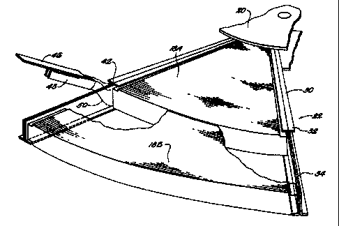
As shown in Fig. 1, and greater detail in Fig. 2-5, the supporting frame 16 of
energy recovery wheel 10 comprises a hub 20 (shown in Figs. 1, 2 and 5),
spokes 22
(shown in Figs. 2-5) and a rim assembly 24 (best shown in Figs. 3 and 4) for
supporting
the energy transfer segments 18 (shown in detail in Figs. 2 and 5). The frame
16 of the
wheel 10 is preferably made of a light weight, sturdy material, such as
aluminum or
steel. The frame includes a plurality of spokes 22, preferably although not
necessarily
extending radially from the hub 20 to the rim assembly 24, equiangularly
around the
hub. For example, eight spokes spaced 45° apart can be provided,
although the number
and angle can vary. The spokes can also extend at an angle to the radial
direction.
As best shown in Figs. 2-4, each spoke 22 includes an elongated spoke element
30 preferably having an inner I-beam portion 32 attached to the hub 20, and an
outer T-
bar portion 34 extending from the I-beam portion 32 to the rim assembly 24. As
best
seen in Fig. 6, the I-beam portion 32 includes a pair of flanges 36 and 38
with an
-5-
CA 02316827 2004-O1-02
intermediate web 40. The T-bar portion 34 is essentially an extension of one
flange and the
web of the I-beam portion so that the I-beam portion and T-bar portion is
preferably an,
integrated, unitary construction, although the T-bar portion can be made
separately from the
I-beam portion and the two secured together to form a each spoke. The inner I-
beam portion
extends a predetermined distance from the center of the wheel where it
terminates at point 42
(see Fig. 2), while the T-bar portion 34 extends from the termination point 42
of the I-beam
to the outer rim assembly 24 of the frame 16.
With this configuration, two differently shaped energy transfer segments 18A
and 18B
can be utilized, thus providing smaller segments facilitating assembly,
removal, replacement
and/or cleaning of the segments. The inner segment is wedge-shaped, and is
similar to the
prior art segments described, for example, in aforementioned U.S. Patent No.
5,937,933.
When properly positioned in the frame, the inner segment preferably has an
inner arcuate edge
having a radius of curvature so as to cooperate with the hub section, and an
outer axcuate edge
having a radius of curvature that extends exact to the termination point 42,
or a predetermined
distance (e.g., a fraction of an inch) beyond the termination point 42 so that
a portion of the
inner segment extends into the T-bar portion 34 of the two adjacent spoke
elements 22. The
outer energy transfer segment 18B is an arcuate shaped segment and when
properly positioned
in the frame, has an inner radius of curvature substantially the same as the
outer radius of
curvature of the inner segment, and an outer radius of curvature substantially
the same as the
outer rim assembly. Thus, the outer segment 18B is adapted to fit between the
inner segment
18A and the rim assembly 24, and in the T-bar portions 34 of the adjacent
spoke elements.
The energy transfer segments 18A and 18B can be formed from strips of plastic
(e.g.,
high molecular weight, synthetic polymers), aluminum, Kraft or other fibrous
paper, or steel.
Any polymers of a type capable of being heat sealed is preferably used. Each
of the inner and
outer radially positioned segments can be formed, for example, by cutting
completely through
one or more strips which are wound into a wheel and subsequently cut, for
example, with a
heated tool from one face to the opposite face so that the resulting wedge-
shaped or
arcuate-shaped elements each have arc-shaped strips fused at their ends along
the cut line. As
shown in Fig. 6, both the inner and outer segments can be framed with a
suitable frame, such
as a c-channel bracket indicated generally at 44 sized so as to fit within
with the I-beam
construction formed by the spoke
-6-
CA 02316827 2000-06-29
WO 99/35442 PCT/US99100138
element 30. Alternatively. the c-channel bracket can be omitted.
Those skilled in the art will recognize that other matrix construction
techniques
may be employed, and matrices of other configurations. such as those
containing flat
layers, or a honeycomb structure, may be produced. As is known in the art,
suitable
spacing means are provided in the matrix so as to form gas passageways in an
axial
direction through the wheel segments at a given surface area density.
As shown in Fig. 5, the inner pie-shaped segment thus can be positioned
between
the spokes and spaced from the hub, and radially slid into position against
the hub. In
position the inner segment will be secured between the flanges of the two
adjacent I=
beam portions of the adjacent spoke elements, and extend at its outer radial
edge, to or
a short distance past the end of the I-beam flange where the T-bar starts at
the
termination point 42. Ouee t'rie inner segment is in position, the outer
segment can be
axially slid into place between the rim assembly 24 and the inner segment and
between
the T-bar portions 34 of the adjacent spoke elements securing the inner
segment in place.
1 S In order to secure the outer segments within the frame assembly, as seen
in Fig.
2 a bar 46 is provided. The bar 46 preferably locks or clamps the straight
edge of the
outer segment so as to secure the outer segment in place. The bar 46 can be
secured in
any known manner. Preferably, the bar includes means for attaching the bar so
that it
covers the T-bar portion. The bar preferably includes a pair of strips 48 that
are adapted
to extend (as indicated in Fig. 2 by dotted lines 50) into the I-beam portion
of the spoke
element between the straight edge of the inner segment and the web of the I-
beam
portion, and fit over at least a portion of the web 40 of the T-bar portion 34
and the
straight edge of the outer energy transfer segment 18B on the opposite sides
of the
spoke.
The rim assembly preferably includes suitable retainer means, such as the
mechanism 58 shown in Figs. 3 and 4, for retaining the bar 46 in place. The
mechanism
58 preferably includes a pivotal arm 60 attached to the inside of the outer
rim 62, which
pivots about the pivot pin 64 between an open position (seen in position A in
Fig. 4) and
a closed, clamping position (seen in position B in Fig. 3) wherein the arm 60
is held in
place by the catch 66 provided on the inner periphery of the outer rim 62. The
arm 60
is provided with two tabs 68 and 70. Tab 68 is adapted to fit over the outer
end of the
bar 46 when the arm is moved to the closed position so as to secure the bar 46
in place.
_7_
CA 02316827 2000-06-29
WO 99/35442 PCT/US99/00138
The other tab 70 provides the means for moving the arm radially inward so that
it can
clear the catch 66 when moving the arm between the closed position to an open
position.
It should be appreciated that bar 46 can be attached to the frame in other
ways.
For example, the bar 46 can be secured to spoke with one or more fasteners,
such as
screws and/or bolts. The bar can be provided with clips that attach to the web
of the T-,
bar portion. In addition, the bar is shown as extending the length of the T-
bar portion,
but alternatively could be of other lengths, as for example extending further
over the I-
beam portion, or be shortened to cover only a portion of the T-bar portion.
Tr should be noted that the face area of the wheel through which air can flow
is
an important factor affec~:~?Q pressure drop and efficiency of energy transfer
within a
given wheel radius. In the present illustrated desig: , the face area of the
wheel is
reduced by both the width of the I-beam portion of the spoke element 30, and
the
segment frame 44. In a typical wheel design, eight I-beam spokes can represent
as much
as 5% of the total surface area of a wheel, as can the frames 44 of eight
wedge shaped
segments. By nesting the frames 44 of the segments within the I-beam
construction,
flow through area of the wheel will not be appreciably affected.
It should be appreciated that using the I-beam construction provides a light
weight and inexpensive construction for resisting the bending moments caused
by the
counterflowing air streams. Using an I-beam construction, a high proportion of
material
is located in the parallel flanges at the extremities of the beam where
maximum bending
forces of compression and tension occur. Although ideal for reasons of
strength, the
parallel flanges (alternate compression and tension members of the I beam)
occupy face
area of the wheel through which air could otherwise flow, although by nesting
the
brackets of the segments within the I-beam construction, the disadvantage is
minimized.
Further, by using the inner and outer segments, smaller and lighter segments
are
provided facilitating the assembly and removal of the segments. By making the
faces
of the inner and outer segments of substantially the same surface area (the
surface area
normal to the flow of air), they will weigh approximately the same and be one-
half the
size of a single wedge unit of comparable size designed for the same sized
wheel. The
parts provide a convenient way of assembling and disassembling the inner and
outer
radial segments not afforded by a unitary I-shaped cross-section spoke
construction.
-g_
CA 02316827 2000-06-29
PCT/US99/00138
WO 99/35442
This is extremely important in view of the size of the wheels currently being
manufactured, where the segments weigh on the order of 30 pounds each. In
addition,
it is well known that an 1-beam construction provides extremely strong support
against
bending stresses, to which the wheel will be subjected as the wheel rotates in
two
counterflowing airstreams. A unitary T-bar construction does not provide the
support
provided by a unitary I-beam construction. However, Applicants have determined
that
most of the bending stress is concentrated on the inner radial segment, and
thus provided
on the I-shaped cross section of the inner spoke section. This allows for the
outer spoke
section to be of a T-shaped cross section, and creates the ability to provided
thinner (and
thus lighter) matrixes, despite the size of the wheel. It is important to note
that when the
bar clamps the edge of each of two outer segments in the frame, the resulting
structwe
of the T-shaped cross section and bar will not provide the support of an I-
beam
construction, nor does it need to. The clamping bar provides little additional
support to
bending stresses
Other alternative structures can be provided. For example, the inner segments
can be made smaller or larger than the outer segments. In addition, while the
preferred
arrangement is to provide an inner I-beam portion, and the outer T-bar
portion, under
certain circumstances where it is determined for example that most of the
bending
stresses are carried by the outer segment, due for example to the difference
in sizes
between the inner and outer segments, the T-bar portion can be provided as the
inner
portion and the I-beam portion as the outer portion. In this latter case the
outer segment
would first be inserted radially into the I-beam portions of the spokes, and
then the inner
segments would be inserted axially into the T-bar portions of the spokes. In
this case
a bar or other suitable device would secwe the inner segment in place. In
addition,
while two different segments have been shown and described, the wheel can
include
more than two types of different types of segments.
In this disclosure, there are shown and described various preferred
embodiments
of the invention, but as aforementioned, it is to be understood that the
invention is
capable of use in various other conditions and environments and is capable of
changes
or modifications within the scope of the inventive concept as expressed
herein.
-9-