Sélection de la langue

Search

Sommaire du brevet 2317298 

Énoncé de désistement de responsabilité concernant l'information provenant de tiers

Une partie des informations de ce site Web a été fournie par des sources externes. Le gouvernement du Canada n'assume aucune responsabilité concernant la précision, l'actualité ou la fiabilité des informations fournies par les sources externes. Les utilisateurs qui désirent employer cette information devraient consulter directement la source des informations. Le contenu fourni par les sources externes n'est pas assujetti aux exigences sur les langues officielles, la protection des renseignements personnels et l'accessibilité.

Disponibilité de l'Abrégé et des Revendications

L'apparition de différences dans le texte et l'image des Revendications et de l'Abrégé dépend du moment auquel le document est publié. Les textes des Revendications et de l'Abrégé sont affichés :

  • lorsque la demande peut être examinée par le public;
  • lorsque le brevet est émis (délivrance).
(12) Demande de brevet: (11) CA 2317298
(54) Titre français: FIXATION POUR EVIDEMENT AVEUGLE
(54) Titre anglais: BLIND APERTURE FASTENER
Statut: Réputée abandonnée et au-delà du délai pour le rétablissement - en attente de la réponse à l’avis de communication rejetée
Données bibliographiques
(51) Classification internationale des brevets (CIB):
  • F16B 13/10 (2006.01)
  • F16B 21/18 (2006.01)
(72) Inventeurs :
  • LEVEY, KEN (Etats-Unis d'Amérique)
(73) Titulaires :
  • ILLINOIS TOOL WORKS INC.
(71) Demandeurs :
  • ILLINOIS TOOL WORKS INC. (Etats-Unis d'Amérique)
(74) Agent: FINLAYSON & SINGLEHURST
(74) Co-agent:
(45) Délivré:
(22) Date de dépôt: 2000-08-31
(41) Mise à la disponibilité du public: 2001-04-05
Requête d'examen: 2000-08-31
Licence disponible: S.O.
Cédé au domaine public: S.O.
(25) Langue des documents déposés: Anglais

Traité de coopération en matière de brevets (PCT): Non

(30) Données de priorité de la demande:
Numéro de la demande Pays / territoire Date
09/412,277 (Etats-Unis d'Amérique) 1999-10-05

Abrégés

Abrégé anglais


The fastener includes a stud with a post element, a
cylindrical inner sleeve with inwardly extending half-hemispherical
bosses immediately adjacent to outwardly extending
half-hemispherical bosses, and a base element with a blind aperture.
The inner sleeve is received within the blind aperture and the post
element is received within the inner sleeve. The pressure exerted
upon the insertion of the post element of the stud and the
structure of the bosses cause the inner sleeve to cock into a
locked position. The exposed edges of the inwardly extending
half-hemispherical bosses of the inner sleeve engage the post element
while the exposed edges of the outwardly extending
half-hemispherical bosses of the inner sleeve engage the walls of the
blind aperture in order to resist the subsequent withdrawal of the
post element from the blind aperture.

Revendications

Note : Les revendications sont présentées dans la langue officielle dans laquelle elles ont été soumises.


CLAIMS
What is Claimed is:
1. A fastener including:
a stud with a post;
a base with an aperture formed by inner walls therein;
a sleeve including a cylindrical wall and open ends, said
cylindrical wall having an inner diameter and an outer diameter,
said sleeve further including at least one inwardly extending boss
and at least one outwardly extending boss formed on said
cylindrical walls;
said outer diameter and said at least one outwardly extending
boss being sized so that said sleeve can be inserted into said
aperture, and said inner diameter and said at least one inwardly
extending boss being sized so that said post can be inserted into
said sleeve whereby said at least one outwardly extending boss
engages said inner walls and said at least one inwardly extending
boss engages said post.
2. The fastener of Claim 1 wherein said at least one inwardly
extending boss includes a plurality of inwardly extending bosses
and said outwardly extending boss includes a plurality of outwardly
10

3. The fastener of Claim 2 wherein each of said plurality of
inwardly extending bosses is immediately adjacent to a respective
one of said plurality of outwardly extending bosses.
4. The fastener of Claim 3 wherein said plurality of inwardly
extending bosses and said plurality of outwardly extending bosses
is formed from half hemispheres.
5. The fastener of Claim 4 wherein each of said plurality of
inwardly extending bosses shares a geometric center with a
respective one of said plurality of outwardly extending bosses.
6. The fastener of Claim 5 wherein each of said plurality of
inwardly extending bosses presents a first edge and each of said
plurality of outwardly extending bosses presents a second edge,
wherein each of said first edges is formed from a common seam on
said cylindrical wall with a respective one of said second edges.
7. The fastener of Claim 6 wherein said cylindrical wall of said
sleeve includes a longitudinally oriented gap.
8. The fastener of Claim 7 wherein said sleeve is formed from
sheet metal and said plurality of inwardly extending bosses and
11

said plurality of outwardly extending bosses are stamped onto said
sleeve.
9. The fastener of Claim 8 wherein said blind aperture includes
a stop to limit insertion of said sleeve therein.
10. The fastener of Claim 9 wherein said stop is a cylindrical
chamfered section leading to a portion of reduced diameter.
11. The fastener of Claim 10 wherein said portion of reduced
diameter has a diameter to receive said post.
12. The fastener of Claim 11 further including a ring adjacent to
said post, said ring being of greater diameter than said post, said
aperture including a mouth with a diameter to receive said ring.
12

Description

Note : Les descriptions sont présentées dans la langue officielle dans laquelle elles ont été soumises.

CA 02317298 2000-08-31
029-76 BLIND APERTURE FASTENER
BACKGROUND OF THE INVENTION
Field of the Invention
This invention pertains to a fastener with a stud, an inner
sleeve and a base member. The stud includes a post which fits into
a blind aperture in the base member. The sleeve fits between the
post and the base member and includes a boss structure which locks
the post into the base member.
Description of the Prior Art
In the prior art, fasteners with a post which inserts into a
blind aperture within the base member are known. However, to
insure a tight fit between the post and the base member, relatively
accurate manufacturing tolerances were required. Similarly, these _--
fasteners frequently had intricate or complex shapes which had to
be manufactured precisely. Additionally, many of these fasteners
require complicated installation procedures, such as twisting, or
specialized installation tools. All of these factors can add to
the final total cost of such a fastener.

CA 02317298 2000-08-31
OBJECTS AND SUMMARY OF THE INVENTION
It is therefore an object of this invention to provide a
fastener which has relatively relaxed manufacturing tolerances.
It is therefore a further object of this invention to provide
a fastener which has a reduced complexity of structure.
It is therefore a still further object of this invention to
provide a fastener which has a simple installation process.
It is therefore a final object of this invention to provide a
fastener which reduces or eliminates the need for specialized tools
in the installation process.
These and other objects are attained by providing a fastener
with a base element including a blind aperture, a stud with a post
element which fits into the blind aperture, and an inner sleeve
which fits between the walls of the blind aperture and the post
element. The inner sleeve includes inwardly and outwardly
extending protrusions which function as boss elements against the
post and base element, respectively. These protrusions ride
smoothly on the walls of the blind aperture of the base element
upon insertion of the post element into the blind aperture.
Stamping of the stud into the aperture causes the protrusions to
"cock" into a locked position. Additionally, the inner sleeve
includes a longitudinally oriented slot in order to allow the
2

CA 02317298 2000-08-31
sleeve to accommodate somewhat varying sizes of the blind aperture
and post.

CA 02317298 2000-08-31
BRIEF DESCRIPTION OF THE DRAWINGS
Further objects and advantages of the invention will become
apparent from the following description and claims, and from the
accompanying drawings, wherein:
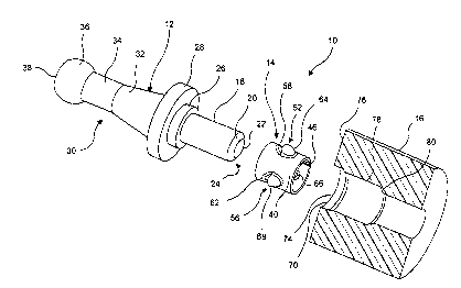
Figure 1 is an exploded partially cut-away perspective view of
the fastener of the present -invention.
Figure 2 is a partially cut-away perspective view of the
fastener of the present invention in the engaged position.
Figure 3 is a cross-sectional view of the fastener of the
present invention in the engaged position.
Figure 4 is a perspective view of the inner sleeve of the
fastener of the present invention.
DETAILED DESCRIPTION OF THE PREFERRED EMBODIMENT
Referring now to the drawings in detail wherein like numerals ---
indicate like elements throughout the several views, one sees from
Figures 1, 2 and 3 that fastener 10 includes stud 12, inner sleeve
14 and base element 16.
Stud 12 is radially symmetric and includes cylindrical post
element 18 with chamfer 20 on tip 22 on distal end 24. Proximal
end of cylindrical post element 18 includes enlarged stabilizing
ring 26 (optional, as described hereinafter). Cylindrical base 28
4

CA 02317298 2000-08-31
is formed adjacent to stabilizing ring 26. Gripping element 30 is
formed adjacent to cylindrical base 28 and, in the illustrated
embodiment, consecutively includes frusto-conical portion 32,
cylindrical portion 34 and partially hemispherical head 36 with
outer planar surface 38.
Stud 12 is typically formed of glass-filled plastic, but those
skilled in the art will recognize that other materials may be used.
Stud 12 is typically molded as a single integral piece.
Inner sleeve 14 is typically formed from sheet metal or a
similar material. As shown in Figure 4, the sheet metal forms
roughly cylindrical walls 40 with open ends 42, 44. However,
longitudinal slot or gap 46 is formed between ends 48, 50 of the
sheet metal. Longitudinal slot or gap 46 allows for flexure of
cylindrical walls 40 during installation.
Boss structures 52, 54, 56 are formed about the periphery of
cylindrical walls 40. Boss structures 52, 54, 56 include inwardly
extending half-hemispherical bosses 58, 60, 62, respectively, which
are formed immediately adjacent to outwardly extending half-
hemispherical bosses 64, 66, 68, respectively. As can be seen from
Figure 4, in boss structure 52, outwardly extending half-
hemispherical boss 64 shares substantially the same geometric
center as inwardly extending half-hemispherical boss 58.

CA 02317298 2000-08-31
Additionally, the exposed edge of outwardly extending half-
hemispherical boss 64 is formed from a common original seam in
inner sleeve 14 as the exposed edge of inwardly extending half-
hemispherical boss 58. Boss structures 54, 56 are similarly
formed. The shape and immediately adjacent structure of the
inwardly extending half-hemispherical bosses 58, 60, 62 with the
outwardly extending half-hemispherical bosses 64, 66, 68 allow for
the formation of a sharp exposed edge on the bosses 58-68 with a
simple sheet metal stamping process. Additionally, this structure
allows the bosses 58-68 to maintain their shape under load and to
be pushed into blind aperture 70 with the lowest possible friction
and ease of manufacturing. However, a variety of shaped dimples
would be possible such as a dimple with a radius equal to or less
than the inner diameter radius of blind aperture 70, an oval, a
triangle, a cone, a square, a rectangle or any other shape which
would present an edge to grab the plastic when opposing force is
applied. It is further important that the dimples do not
inelastically or otherwise permanently deform the inner diameter of
blind aperture 70 in such a way that the boss edges no longer have
the ability of interfering with the inner diameter of blind
aperture 70.
Base element 16 is typically formed of plastic or a similar
6

CA 02317298 2000-08-31
material. Base element 16 is roughly cylindrical with blind
aperture 70 formed about the longitudinal axis thereof. Blind
aperture 70 includes enlarged portion 72 which forms mouth 74 in
planar surface 76. Enlarged portion 72 has a diameter to
accommodate stabilizing ring 26. This gives fastener 10 additional
stability against lateral forces. Central portion 78 of blind
aperture 70 is formed adjacent to enlarged portion 72 and is sized
to allow inner sleeve 14 to fit therein and to be engaged by inner
sleeve 14 when cylindrical post element 18 is inserted into inner
sleeve 14. While stabilizing ring 26 and enlarged portion 76 are
illustrated in the drawings and described herein, these element s
should be considered optional in that it may be at least equally
preferred to omit these elements. Cylindrical chamfered stop
section 80 is formed adjacent to central portion 78 and serves to
limit the insertion of inner sleeve 14 into blind aperture 70.
Cylindrical chamfered stop section 80 leads to blind aperture
portion 82 which has a diameter to receive cylindrical post element
18.
To use fastener 10, the installer typically inserts inner
sleeve 14 into central portion 78 of blind aperture 70 as limited
by cylindrical chamfered stop section 80 and aligns blind,aperture
70 with the first side of an aperture in a panel or panels to be
7

CA 02317298 2000-08-31
fastened (not shown). The user then pushes cylindrical post
element 18 through the second side of the aperture in the panel or
panels to be fastened (not shown) and into cylindrical sleeve 14
which is positioned within blind aperture 70. Stud 12 can then be
stamped into position thereby driving post element 18 so that edges
of inwardly extending half-hemispherical bosses 58, 60, 62 engage
post element 18 and outwardly extending half-hemispherical bosses
64, 66, 68 engage the walls of blind aperture 70. The pressure
exerted upon the insertion of stud 12 and the stamping into blind
aperture 70 cause the inner diameter and the outer diameter of
inner sleeve 14, along with inwardly extending half-hemispherical
bosses 58, 60, 62 and outwardly extending half-hemispherical bosses
64, 66, 68, cause inner sleeve 14 to "cock" into position. Any
subsequent forces attempting to withdraw stud 12 from base element
16 are opposed by the engagement of bosses 58-68 as described
above. The final locked position of fastener 10 typically has
planar surface 76 flush with a first side of the panel or panels to
be fastened and cylindrical base 28 of stud 12 flush with a second
side of the panel or panels to be fastened. The order of steps
above is meant to be illustrative and those skilled in the art
could have occasion to use a different order of steps of
installation. -
8

CA 02317298 2000-08-31
Thus the several aforementioned objects and advantages are
most effectively attained. Although a single preferred embodiment
of the invention has been disclosed and described in detail herein,
it should be understood that this invention is in no sense limited
thereby and its scope is to be determined by that of the appended
claims.
9

Dessin représentatif
Une figure unique qui représente un dessin illustrant l'invention.
États administratifs

2024-08-01 : Dans le cadre de la transition vers les Brevets de nouvelle génération (BNG), la base de données sur les brevets canadiens (BDBC) contient désormais un Historique d'événement plus détaillé, qui reproduit le Journal des événements de notre nouvelle solution interne.

Veuillez noter que les événements débutant par « Inactive : » se réfèrent à des événements qui ne sont plus utilisés dans notre nouvelle solution interne.

Pour une meilleure compréhension de l'état de la demande ou brevet qui figure sur cette page, la rubrique Mise en garde , et les descriptions de Brevet , Historique d'événement , Taxes périodiques et Historique des paiements devraient être consultées.

Historique d'événement

Description Date
Inactive : CIB de MCD 2006-03-12
Demande non rétablie avant l'échéance 2004-08-09
Inactive : Morte - Aucune rép. dem. par.30(2) Règles 2004-08-09
Réputée abandonnée - omission de répondre à un avis sur les taxes pour le maintien en état 2003-09-02
Inactive : Abandon. - Aucune rép dem par.30(2) Règles 2003-08-07
Inactive : Dem. de l'examinateur par.30(2) Règles 2003-02-07
Demande publiée (accessible au public) 2001-04-05
Inactive : Page couverture publiée 2001-04-04
Inactive : CIB en 1re position 2000-10-11
Exigences de dépôt - jugé conforme 2000-09-21
Lettre envoyée 2000-09-21
Inactive : Certificat de dépôt - RE (Anglais) 2000-09-21
Demande reçue - nationale ordinaire 2000-09-20
Exigences pour une requête d'examen - jugée conforme 2000-08-31
Toutes les exigences pour l'examen - jugée conforme 2000-08-31

Historique d'abandonnement

Date d'abandonnement Raison Date de rétablissement
2003-09-02

Taxes périodiques

Le dernier paiement a été reçu le 2002-08-13

Avis : Si le paiement en totalité n'a pas été reçu au plus tard à la date indiquée, une taxe supplémentaire peut être imposée, soit une des taxes suivantes :

  • taxe de rétablissement ;
  • taxe pour paiement en souffrance ; ou
  • taxe additionnelle pour le renversement d'une péremption réputée.

Les taxes sur les brevets sont ajustées au 1er janvier de chaque année. Les montants ci-dessus sont les montants actuels s'ils sont reçus au plus tard le 31 décembre de l'année en cours.
Veuillez vous référer à la page web des taxes sur les brevets de l'OPIC pour voir tous les montants actuels des taxes.

Historique des taxes

Type de taxes Anniversaire Échéance Date payée
Taxe pour le dépôt - générale 2000-08-31
Enregistrement d'un document 2000-08-31
Requête d'examen - générale 2000-08-31
TM (demande, 2e anniv.) - générale 02 2002-09-02 2002-08-13
Titulaires au dossier

Les titulaires actuels et antérieures au dossier sont affichés en ordre alphabétique.

Titulaires actuels au dossier
ILLINOIS TOOL WORKS INC.
Titulaires antérieures au dossier
KEN LEVEY
Les propriétaires antérieurs qui ne figurent pas dans la liste des « Propriétaires au dossier » apparaîtront dans d'autres documents au dossier.
Documents

Pour visionner les fichiers sélectionnés, entrer le code reCAPTCHA :


Pour visualiser une image, cliquer sur un lien dans la colonne description du document. Pour télécharger l'image (les images), cliquer l'une ou plusieurs cases à cocher dans la première colonne et ensuite cliquer sur le bouton "Télécharger sélection en format PDF (archive Zip)" ou le bouton "Télécharger sélection (en un fichier PDF fusionné)".

Liste des documents de brevet publiés et non publiés sur la BDBC .

Si vous avez des difficultés à accéder au contenu, veuillez communiquer avec le Centre de services à la clientèle au 1-866-997-1936, ou envoyer un courriel au Centre de service à la clientèle de l'OPIC.


Description du
Document 
Date
(aaaa-mm-jj) 
Nombre de pages   Taille de l'image (Ko) 
Dessin représentatif 2001-03-19 1 10
Description 2000-08-30 9 259
Revendications 2000-08-30 3 77
Abrégé 2000-08-30 1 26
Dessins 2000-08-30 4 91
Courtoisie - Certificat d'enregistrement (document(s) connexe(s)) 2000-09-20 1 120
Certificat de dépôt (anglais) 2000-09-20 1 163
Rappel de taxe de maintien due 2002-04-30 1 111
Courtoisie - Lettre d'abandon (taxe de maintien en état) 2003-10-27 1 176
Courtoisie - Lettre d'abandon (R30(2)) 2003-10-15 1 166