Sélection de la langue

Search

Sommaire du brevet 2319235 

Énoncé de désistement de responsabilité concernant l'information provenant de tiers

Une partie des informations de ce site Web a été fournie par des sources externes. Le gouvernement du Canada n'assume aucune responsabilité concernant la précision, l'actualité ou la fiabilité des informations fournies par les sources externes. Les utilisateurs qui désirent employer cette information devraient consulter directement la source des informations. Le contenu fourni par les sources externes n'est pas assujetti aux exigences sur les langues officielles, la protection des renseignements personnels et l'accessibilité.

Disponibilité de l'Abrégé et des Revendications

L'apparition de différences dans le texte et l'image des Revendications et de l'Abrégé dépend du moment auquel le document est publié. Les textes des Revendications et de l'Abrégé sont affichés :

  • lorsque la demande peut être examinée par le public;
  • lorsque le brevet est émis (délivrance).
(12) Demande de brevet: (11) CA 2319235
(54) Titre français: INSTRUMENT DE FIXATION
(54) Titre anglais: A CLAMPING TOOL
Statut: Réputée abandonnée et au-delà du délai pour le rétablissement - en attente de la réponse à l’avis de communication rejetée
Données bibliographiques
(51) Classification internationale des brevets (CIB):
  • A01B 23/02 (2006.01)
  • A01B 35/22 (2006.01)
  • F16B 07/04 (2006.01)
(72) Inventeurs :
  • HANSEN, STEEN ANKER (Danemark)
(73) Titulaires :
  • KONGSKILDE INDUSTRIES A/S
(71) Demandeurs :
  • KONGSKILDE INDUSTRIES A/S (Danemark)
(74) Agent: DENNISON ASSOCIATES
(74) Co-agent:
(45) Délivré:
(86) Date de dépôt PCT: 1999-02-03
(87) Mise à la disponibilité du public: 1999-08-12
Requête d'examen: 2004-01-28
Licence disponible: S.O.
Cédé au domaine public: S.O.
(25) Langue des documents déposés: Anglais

Traité de coopération en matière de brevets (PCT): Oui
(86) Numéro de la demande PCT: PCT/DK1999/000054
(87) Numéro de publication internationale PCT: DK1999000054
(85) Entrée nationale: 2000-07-26

(30) Données de priorité de la demande:
Numéro de la demande Pays / territoire Date
0160/98 (Danemark) 1998-02-05

Abrégés

Abrégé français

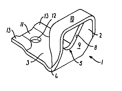
L'invention concerne un élément de fixation (1) conçu pour fixer une pièce à un équipement agricole, plus particulièrement pour fixer une dent à un élément de structure et qui comprend un morceau de feuille en acier qui est divisée par un fléchissement (4) en deux branches (2, 3). Une des branches (2) présente une ouverture (5) ayant un bord (8), sensiblement plan, destiné à recevoir une partie d'une pièce à fixer, la feuille comprenant le long du bord (8) une partie (9) s'étendant vers le fléchissement (4) et une partie restante (10) entourant l'ouverture (5) et s'étendant de préférence sensiblement perpendiculaire à et depuis le plan du bord (8) d'ouverture en s'éloignant de la seconde branche (3).


Abrégé anglais


The clamp (1) is intended for securing a workpiece to an agricultural
implement, in particular for securing a cultivator tine to a frame member, and
comprises a piece of steel sheet which by a bending (4) is divided into two
legs (2, 3), one leg (2) of which has an aperture (5) with an edge (8), which
is substantially positioned in a plane, for receiving a part of a workpiece to
be secured, the sheet material comprising along the edge (8) a part (9)
extending towards the bending (4) and a remaining part (10) extending around
the aperture (5) and extending from, and preferably substantially
perpendicular to, the plane of the aperture edge (8) in a direction away from
the second leg (3).

Revendications

Note : Les revendications sont présentées dans la langue officielle dans laquelle elles ont été soumises.


6
CLAIMS
1. A clamp (1) for securing a workpiece to an
agricultural implement, in particular for securing a
cultivator tine (6) to a frame member (7), comprising
a piece of steel sheet which by a bending (4) is
divided into two legs (2, 3), one leg (2) of which has
an aperture (5) through the steel sheet with an edge
(8), which is substantially positioned in a plane, for
receiving a part of a workpiece to be secured, in
particular an end (6) of a cultivator tine or a tine
spring, the sheet material comprising along the edge
(8) a part (9) extending towards the bending (4) and a
remaining part (10) extending around the aperture (5),
characterized in that the remaining part
(10) of the material around the aperture (5) extends
out of, and preferably substantially perpendicular to,
the plane of the aperture edge (8) in a direction away
from the second leg (3).
2. A clamp according to claim 1, characterized
in that the second leg (3) has an
aperture (12) for receiving a clamping bolt, and that
a part (13) of the sheet material adjacent to this
aperture (12) has been pressed down to the same side as
the first leg (2), the result being an inclining
transition (14) from the part (13), which has been
pressed down, to the remaining part of the second leg
(3).
3. A clamp according to claim 1 or 2, characterized
in that the aperture in the first
leg (2) forms a substantially isosceles triangle with
round corners and its vertex facing the second leg (3).
4. A clamp according to claims 1-3, characterized
in that the clamp has a degree of
hardness in the range of 43-49 HRC.
5. A method for the manufacture of a clamp

7
according to claim 1, characterized in that a
plane steel sheet blank (1') with a first and a second
end (2', 3') is provided, the first end (2') being
provided with a throughgoing aperture (5') with an
edge, a part of the material of the blank along the
edge extending towards the other end (3') of the blank
(1'), and the remaining part (10') extending around the
aperture (5'), that the remaining part (10') by
temperature deformation is bent out of the plane of the
blank (1'), preferably to a position substantially
perpendicular to the plane of the blank, and that the
blank (1') is angularly bent.
6. A method according to claim 5, characterized
in that the blank (1') is manufactured
with a width which is bigger at the first end (2') than
at the second end (3').
7. A method according to claims 5 or 6, characterized
in that the blank (1') is provided
with a comparatively narrow apeture (5') which is
extended with respect to the width during the heat
deformation which is substantially a stretching.
8. A method according to claims 5-7, characterized
in that the second end (3') is provided
with impressions (13) at the sides.
9. A method according to claims 5-6, characterized
in that the blank after the moulding is
hardened to a degree of hardness in the range of 43-49
HRC.
10. An agricultural implement, in particular a
harrow, provided With a member (6) secured on a frame
part (7), in which the member (6) is secured by means
of a clamp (1) according to claims 1-4.

Description

Note : Les descriptions sont présentées dans la langue officielle dans laquelle elles ont été soumises.


~
. .. .~', .: ~~ .. .. ..
. ' . , ~ .. . . .. .
. . ~ ~ . . . ; ' . . , , ,
~ ~ ~ ~ ~ ~ ~ ..
~ ~ ~ ~ . ..
~ .... ... .. .... .. ..
1
A CLAMP
The present invention relates to a clamp for
securing a workpiece to an agricultural implement, in
particular for securing a cultivator tine to a frame
member, comprising a piece of steel sheet which by a
bending is divided into two legs, one leg of which has
an aperture through the steel sheet with an edge, which
is substantially positioned in a plane, for receiving
a part of a workpiece to be secured, in particular an
end of a cultivator tine or a tine spring, the sheet
material comprising along the edge a part extending
towards the bending and a remaining part extending
around the aperture.
Such a clamp is known for instance from GB-A-2 050
131, which discloses a clamp made from a rectangular
piece of steel sheet which is provided with two aper-
tures, one for receiving the end of a cultivator tine
and one for receiving a bolt with a tapered head for
clamping the second leg of the clamp and the end of the
cultivator tine around a frame member, to which the
cultivator tine is to be secured. The effect of using
a bolt with a tapered head is that the first leg of the
clamp is tightened against the frame member.
DK 101 615 C discloses a clamp for securing a
cultivator tine to a frame member and being made from
a piece of steel bar which is bent into a kink and two
branches the latter being held together by a clamping
block when the clamp is used. When in use the kink
3o emends around the cultivator tine and the branches
extends over the frame member.
The object of the invention is to provide an
improved clamp.
The obj ect is met by a clamp of the type mentioned
by way of introduction which is characterized in that
.~.:~afr~:~Y;a~x?""~Y?~s ~~r~:::~-,x?~.~,{<;
t~
:i;:..;~.'',F::y:nr::,Fk.:k.
ANrENDED S~-IEET fi.
'~. v'w'231923~5 2000-07-26

' ~ a as
as a a as as 'a as as
a a a a ' a a ~ a a a
'' ' a a a a' a a ~ a a
a a a a a a a a
a ' aaaa caa ~a aaaa as as
2
the remaining part of the material around the aperture
extends out of, and preferably substantially perpen-
dicular to, the plane of the aperture edge in a direc-
tion away from the second leg.
The result is that the width of the clamp can be
reduced to the width of the workpiece to be secured,
and twice the thickness of the sheet material, which is
an advantage as it provides a higher degree of freedom
for the lateral positioning of for instance a cultiva-
for tine on a frame member. Moreover, a saving of
material is obtained, as the width of the second leg of
the clamp may be smaller than usual. Finally, a bigger
abutment surface against the workpiece to be fastened
is obtained, as the sheet material of the clamp around
the aperture has been turned 90° in comparison with
known clamps and bears flatly against the workpiece to
be fastened..
The second leg preferably has an aperture for
receiving a clamping bolt, and a part of the sheet
material adjacent to this aperture has been pressed
down to the same side as the first leg, the result
being an inclining transition from the part, which has
been pressed down, to the remaining part of the second
leg. By clamping, the inclining transition between the
part, which has been pressed down, and the remaining
part of the second leg of the clamp will have the same
effect as the bolt with the tapered head used according
to the above-mentioned GB-A-2 050 131, which makes it
possible, with the clamp according to the invention, to
use an ordinary standard bolt instead of the tapered,
special bolt, which results in economy saving when
replacing the bolt in case of ruptures.
The aperture in the first leg preferably forms a
substantially isosceles triangle with round corners and
its vertex facing the second leg. In this way an advan
:w:.2~_~:~~n~:,>..-::,.~~:~;~s~:w,.;::,v , .:
v ~~;v'. >~'. z
<.:: : ~.;>.::.
.~A 02319235 2000-0~-26 ~r'UEN~~~ ~'~'r'=T
a ~ Lu v3 ;~_

,
-. .. " ~ .. ..
~ ~ ~ : " ~ ~ ~ ~ . ~'. , ~.
.. . . ..
..
~ ~ .... ... ~ ~ ~ ~ . . ,
.. .... .. ..
3
tageous distribution of the tensions in the material is
obtained.
The clamp preferably has a degree of hardnes s in
the range of 43-49 HRC.
The object of the invention is further met by a
method for the manufacture of a clamp according to the
invention, which is characterized in that a plane steel
sheet blank with a first and a second end is provided,
the first end being provided with a throughgoing
aperture with an edge, a part ~ of the material of the
blank along the edge extending towards the other end of
the blank, the remaining part extending around the
aperture, and that the remaining part by temperature
deformation is bent out of the plane of the blank,
preferably to a position substantially perpendicular to
the plane of the blank; and that the blank is angularly
bent.
Preferred embodiments of the method appear from
the dependent claims 6-9.
The invention also relates to an agricultural
implement, in particular a cultivator with a member
clamped on a frame member, the member being clamped by
means of a clamp according to claims 1-4.
The invention will be explained in detail in the
following by means of an example of an embodiment with
reference to the drawing, in which
Fig. 1 is an isometric view of a clamp,
Fig. 2 shows a blank for the manufacture of the
clamping means prior to shaping,
Fig. 3 shows the blank according to Fig. 2 after
the deformation of the material around the aperture in
the first leg,
Figs 4-6 show the finished clamp, seen in three
mutually perpendicular directions,
Fig. 7 is a sectional view along the line VII-VII
.f~,:N:n'..:~.r.r~.:.,;.:>,:c,:_t';y'.:»:: ~:~r.:vr::.~::; _
:~'i~.~~~'~1R4~~SJ~u ~, :__~
' w vCA 02319235 2000-07-26

~
. ..
~. .. . ' ~~ ..
~ .. ~~ ..
. . . , ~ ~ . . . . . . .
..
~ . , ~ ~ ~ . . . ..
~ ~ .... ... ~..' .:.. ~ ~ .
34
in Fig. 6, and
Fig. 8 illustrates the use of the clamp.
Figs 1 and 4-8 show a clamp 1 with a first leg 2
and a second leg 3, the first and the second legs 2, 3
meeting in a bending 4.
The first leg is provided with an aperture 5 for
receiving the end of a member, for instance a cultiva-
tor tine spring 6, which is to be clamped on a frame
.,..:s:;f..~.:~.. w~::;>.:o>:;...;r., t ~-"~.;.. r.,, n:
n f~.wE :~'v. ~i ~ - _ .. d
...... : .. t
..,::~:~:::f.:.:::.::,:.:.-,..:CA 02319235 2000-07-26 #:

WO 99/39560 PCT/DK99/00054
4
member, like for instance a square tube, of an agricul-
tural implement.
The aperture 5 is defined by an edge 8, positioned
in the plane of the first leg 2. A part 9 of the
material of the clamp bordering the edge B, extends
towards the bending 4, whereas another part 10 of the
material bordering the edge 8 is bent approx. 90° to a
position perpendicular to the plane of the edge 8, as
will appear from the figures.
The end 11 of the second leg 3 opposite the
bending 4 is provided with an aperture 12 for receiving
a bolt as shown in Fig. 8. The area 13 next to the
aperture 12 has been pressed down to the side, in which
the first leg 2 extends, whereby inclining areas 14
have been provided between the areas 13, which have
been pressed down, and the remaining part of the second
leg 3.
At the bending 4, a bulging 15 has been created,
said bulging being known per se.
The clamp is used in a manner known per se as
shown in Fig. 8, a cultivator tine spring 6 being
fastened to a square tube 7 by means of the clamp 1 and
a bolt 16. The cultivator tine spring 6 is passed
through aperture 5 in the first leg, and the bolt 16
extends through a hole in the cultivator tine spring 6
and through the aperture 12 in the clamp to clamp these
two members around the square tube 7. The inclining
areas 14 abut a corner 17 of the square tube 7 and
thereby pull the first leg 2 into abutment against the
side 38 of the square tube.
On account of the bent part 10, a relatively big
abutment surface is obtained between the clamp 1 and
the cultivator tine spring 6 relative to what is
obtained,by the known clamps, a smaller surface pres
sure resulting.
CA 02319235 2000-07-26

WO 99/39560 PCT/DK99/00054
As will in particular appear from Fig. 4, the
clamp 1 is only twice the material thickness of the
part 10 wider than the aperture 5, which in turn is
dimensioned according to the cultivator tine spring 6
5 or another member, with which the clamp is to be used.
The clamp 1 according to the invention is thus narrower
than similar known clamps. It is advantageous as it
leaves more space for obtaining the exact positioning
of the cultivator tine spring 6 along the square tube
7, which may carry many other members than cultivator
tine springs.
The bulging 15 acts in a manner known per se to
take up manufacturing tolerances between the square
tube 7 and the clamp 1, and to prevent the second leg
3 from being brought first into abutment against the
square tube 7 close to the bending 4, which would give
a too big clamping force in the first leg 2 of the
clamp.
The clamp 1 is manufactured by cutting out a clamp
blank 1' from a steel sheet having an aperture 5' at
one end 2', and an aperture 12' at the other end 3'.
The aperture 5' is narrower than the aperture 5 in the
finished workpiece. Through temperature deformation a
part 10' of the blank 1' is bent, said part extending
around the aperture 5', approx. 90°, such that the
blank 1' is given the shape shown in Fig. 3, in which
the part 10' extends upwards from the plane of the
drawing. The deformation is substantially a stretching
deformation. Then the areas around the aperture 12' are
pressed down, and the blank 1' bent into the design
shown in Figs 1 and 4-8. Finally, the blank is tempered
to a hardness of 43-49 HRC.
CA 02319235 2000-07-26

Dessin représentatif
Une figure unique qui représente un dessin illustrant l'invention.
États administratifs

2024-08-01 : Dans le cadre de la transition vers les Brevets de nouvelle génération (BNG), la base de données sur les brevets canadiens (BDBC) contient désormais un Historique d'événement plus détaillé, qui reproduit le Journal des événements de notre nouvelle solution interne.

Veuillez noter que les événements débutant par « Inactive : » se réfèrent à des événements qui ne sont plus utilisés dans notre nouvelle solution interne.

Pour une meilleure compréhension de l'état de la demande ou brevet qui figure sur cette page, la rubrique Mise en garde , et les descriptions de Brevet , Historique d'événement , Taxes périodiques et Historique des paiements devraient être consultées.

Historique d'événement

Description Date
Inactive : CIB de MCD 2006-03-12
Demande non rétablie avant l'échéance 2006-02-03
Le délai pour l'annulation est expiré 2006-02-03
Réputée abandonnée - omission de répondre à un avis sur les taxes pour le maintien en état 2005-02-03
Lettre envoyée 2004-02-04
Requête d'examen reçue 2004-01-28
Exigences pour une requête d'examen - jugée conforme 2004-01-28
Toutes les exigences pour l'examen - jugée conforme 2004-01-28
Lettre envoyée 2001-02-26
Exigences de rétablissement - réputé conforme pour tous les motifs d'abandon 2001-02-14
Réputée abandonnée - omission de répondre à un avis sur les taxes pour le maintien en état 2001-02-05
Lettre envoyée 2000-11-23
Inactive : Page couverture publiée 2000-11-09
Inactive : CIB en 1re position 2000-11-02
Inactive : Lettre de courtoisie - Preuve 2000-10-24
Inactive : Notice - Entrée phase nat. - Pas de RE 2000-10-17
Demande reçue - PCT 2000-10-12
Inactive : Transfert individuel 2000-09-28
Demande publiée (accessible au public) 1999-08-12

Historique d'abandonnement

Date d'abandonnement Raison Date de rétablissement
2005-02-03
2001-02-05

Taxes périodiques

Le dernier paiement a été reçu le 2004-01-28

Avis : Si le paiement en totalité n'a pas été reçu au plus tard à la date indiquée, une taxe supplémentaire peut être imposée, soit une des taxes suivantes :

  • taxe de rétablissement ;
  • taxe pour paiement en souffrance ; ou
  • taxe additionnelle pour le renversement d'une péremption réputée.

Les taxes sur les brevets sont ajustées au 1er janvier de chaque année. Les montants ci-dessus sont les montants actuels s'ils sont reçus au plus tard le 31 décembre de l'année en cours.
Veuillez vous référer à la page web des taxes sur les brevets de l'OPIC pour voir tous les montants actuels des taxes.

Historique des taxes

Type de taxes Anniversaire Échéance Date payée
Taxe nationale de base - générale 2000-07-26
Enregistrement d'un document 2000-09-28
Rétablissement 2001-02-14
TM (demande, 2e anniv.) - générale 02 2001-02-05 2001-02-14
TM (demande, 3e anniv.) - générale 03 2002-02-04 2002-01-31
TM (demande, 4e anniv.) - générale 04 2003-02-03 2003-02-03
TM (demande, 5e anniv.) - générale 05 2004-02-03 2004-01-28
Requête d'examen - générale 2004-01-28
Titulaires au dossier

Les titulaires actuels et antérieures au dossier sont affichés en ordre alphabétique.

Titulaires actuels au dossier
KONGSKILDE INDUSTRIES A/S
Titulaires antérieures au dossier
STEEN ANKER HANSEN
Les propriétaires antérieurs qui ne figurent pas dans la liste des « Propriétaires au dossier » apparaîtront dans d'autres documents au dossier.
Documents

Pour visionner les fichiers sélectionnés, entrer le code reCAPTCHA :


Pour visualiser une image, cliquer sur un lien dans la colonne description du document. Pour télécharger l'image (les images), cliquer l'une ou plusieurs cases à cocher dans la première colonne et ensuite cliquer sur le bouton "Télécharger sélection en format PDF (archive Zip)" ou le bouton "Télécharger sélection (en un fichier PDF fusionné)".

Liste des documents de brevet publiés et non publiés sur la BDBC .

Si vous avez des difficultés à accéder au contenu, veuillez communiquer avec le Centre de services à la clientèle au 1-866-997-1936, ou envoyer un courriel au Centre de service à la clientèle de l'OPIC.


Description du
Document 
Date
(aaaa-mm-jj) 
Nombre de pages   Taille de l'image (Ko) 
Dessin représentatif 2000-11-08 1 7
Description 2000-07-25 6 301
Abrégé 2000-07-25 1 59
Revendications 2000-07-25 2 115
Dessins 2000-07-25 3 39
Rappel de taxe de maintien due 2000-10-15 1 110
Avis d'entree dans la phase nationale 2000-10-16 1 193
Courtoisie - Certificat d'enregistrement (document(s) connexe(s)) 2000-11-22 1 113
Courtoisie - Lettre d'abandon (taxe de maintien en état) 2001-02-25 1 182
Avis de retablissement 2001-02-25 1 169
Rappel - requête d'examen 2003-10-05 1 112
Accusé de réception de la requête d'examen 2004-02-03 1 174
Courtoisie - Lettre d'abandon (taxe de maintien en état) 2005-03-30 1 174
Correspondance 2000-10-16 1 14
PCT 2000-07-25 14 531