Sélection de la langue

Search

Sommaire du brevet 2321249 

Énoncé de désistement de responsabilité concernant l'information provenant de tiers

Une partie des informations de ce site Web a été fournie par des sources externes. Le gouvernement du Canada n'assume aucune responsabilité concernant la précision, l'actualité ou la fiabilité des informations fournies par les sources externes. Les utilisateurs qui désirent employer cette information devraient consulter directement la source des informations. Le contenu fourni par les sources externes n'est pas assujetti aux exigences sur les langues officielles, la protection des renseignements personnels et l'accessibilité.

Disponibilité de l'Abrégé et des Revendications

L'apparition de différences dans le texte et l'image des Revendications et de l'Abrégé dépend du moment auquel le document est publié. Les textes des Revendications et de l'Abrégé sont affichés :

  • lorsque la demande peut être examinée par le public;
  • lorsque le brevet est émis (délivrance).
(12) Demande de brevet: (11) CA 2321249
(54) Titre français: DISPOSITIF D'ALIMENTATION POUR ANIMAUX
(54) Titre anglais: AN IMPLEMENT FOR FEEDING ANIMALS
Statut: Réputée abandonnée et au-delà du délai pour le rétablissement - en attente de la réponse à l’avis de communication rejetée
Données bibliographiques
(51) Classification internationale des brevets (CIB):
  • A01K 5/00 (2006.01)
  • A01D 87/12 (2006.01)
  • A01F 15/07 (2006.01)
  • B65B 69/00 (2006.01)
(72) Inventeurs :
  • VAN DEN BERG, KAREL
(73) Titulaires :
  • LELY ENTERPRISES AG
(71) Demandeurs :
  • LELY ENTERPRISES AG (Suisse)
(74) Agent: SMART & BIGGAR LP
(74) Co-agent:
(45) Délivré:
(86) Date de dépôt PCT: 1999-12-10
(87) Mise à la disponibilité du public: 2000-07-06
Licence disponible: S.O.
Cédé au domaine public: S.O.
(25) Langue des documents déposés: Anglais

Traité de coopération en matière de brevets (PCT): Oui
(86) Numéro de la demande PCT: PCT/NL1999/000758
(87) Numéro de publication internationale PCT: WO 2000038503
(85) Entrée nationale: 2000-08-14

(30) Données de priorité de la demande:
Numéro de la demande Pays / territoire Date
1010899 (Pays-Bas (Royaume des)) 1998-12-24

Abrégés

Abrégé français

Selon cette invention, un dispositif d'alimentation pour animaux comprend une voie d'alimentation (1) pour balles d'aliments (2) sous emballage, un système (3) pour enlever l'emballage enveloppant ces balles (2), un système (4) pour extraire le fourrage contenu dans les balles (2) et pour lui donner une forme adaptée à la consommation et un système (5) pour alimenter le fourrage, qui a une forme adaptée à la consommation, dans une stalle d'alimentation où il sera consommé par les animaux. L'invention permet d'automatiser complètement le traitement des balles (2).


Abrégé anglais


An implement for feeding animals is provided with a supply channel (1) for
wrapped feed bales (2), means (3) for removing the wrapper from a feed bale
(2), means (4) for bringing fodder out of the feed bale (2) into a form which
is suitable for consumption, and means (5) for supplying the fodder that has
been brought into a consumable form to a feeding stall for the animals to be
fed. Thus it is achieved that the bales (2) can be processed fully
automatically.

Revendications

Note : Les revendications sont présentées dans la langue officielle dans laquelle elles ont été soumises.


CLAIMS
1. An implement for feeding animals, characterized in that
the implement is provided with a supply opening and/or a supply
channel (1) for wrapped feed bales (2), means (3) for removing
the wrapper from a feed bale (2), means (4) for bringing fodder
out of the feed bale (2) into a form which is suitable for
consumption, and means (5) for supplying the fodder that has
been brought into a consumable form to a feeding stall for the
animals to be fed.
2. An implement as claimed in claim 1, characterized in
that the supply channel (1) is provided with controllable means
(6, 7) for supplying each time at least one feed bale (2) to the
means (3) for removing the wrapper from a feed bale (2).
3. An implement as claimed in claim 2, characterized in
that the means (6, 7) for supplying each time at least one feed
bale (2) to the means (3) for removing the wrapper from a feed
bale (2) comprise a pivotable element (7) in the shape of a
cylinder casing segment.
4. An implement as claimed in any one of claims 1 to 3,
characterized in that the means (3) for removing the wrapper
from a feed bale (2) are provided with controllable means (8, 9)
for receiving each time one wrapped feed bale (2) and supplying
same, after the wrapper has been removed therefrom, to the means
(4) for bringing fodder out of the feed bale (2) into a form
which is suitable for consumption.
5. An implement as claimed in claim 4, characterized in
that the means (8, 9) for receiving each time one wrapped feed
bale (2) and supplying same, after the wrapper has been removed
therefrom, to the means (4) for bringing fodder out of the feed
bale (2) into a form which is suitable for consumption comprise
a tiltable floor element (9).
6. An implement as claimed in any one of claims 1 to 5,
characterized in that the means (3) for removing the wrapper

6
from a feed bale (2) are provided with means for cutting the
wrapper.
7. An implement as claimed in claim 6, characterized in
that the means for cutting the wrapper comprise a cutting
element (10) extending for the greater part around the feed bale
(2), such as e.g. a cutting thread.
8. An implement as claimed in claim 7, characterized in
that the cutting element (10) is connected with means
(11, 12, 13) for putting the cutting element (10) under tension
against the wrapper of the feed bale (2) or around the wrapper
of the feed bale (2).
9. An implement as claimed in claim 8, characterized in
that the means (11, 12, 13) for putting the cutting element (10)
under tension comprise a first motor (11) connected with one end
of the cutting element (10), and a second motor (12) connected
with the other end of the cutting element (10), the cutting
element (10) making at least at one point a bend and is
suspended there from a framework (14) via a spring element (13).
10. An implement as claimed in any one of claims 7 to 9,
characterized in that the cutting element (10) is connected with
means for heating and/or reciprocating the cutting element (10).
11. An implement as claimed in any one of claims 1 to 10,
characterized in that the means (3) for removing the wrapper
from a feed bale (2) are provided with means (15, 16) for
rotating the feed bale (2).
12. An implement as claimed in any one of claims 1 to 11,
characterized in that the means (3) for removing the wrapper
from a feed bale (2) are provided with means for stripping the
wrapper from the feed bale (2).
13. An implement as claimed in claim 12, characterized in
that the means for stripping the wrapper from the feed bale (2)
comprise two cylindrical rollers (17) which are almost touching
each other and are rotatable in opposite directions.
14. An implement as claimed in any one of claims 1 to 13,
characterized in that the means (3) for removing the wrapper

7
from a feed bale (2) are provided with a device (19) for
discharging the wrapper.
15. An implement as claimed in any one of claims 1 to 14,
characterized in that the means (4) for bringing fodder out of
the feed bale (2) into a form which is suitable for consumption
comprise at least one rotatable cutter or at least one rotatable
knife.
16. An implement as claimed in any one of claims 1 to 14,
characterized in that the means (4) for bringing fodder out of
the feed bale (2) into a form which is suitable for consumption
comprise at least one row of cutting elements (20).
17. An implement as claimed in any one of claims 1 to 16,
characterized in that the means (5) for supplying the fodder
that has been brought into a consumable form to the feeding
stall comprise a controllable nozzle (21).
18. An implement as claimed in claim 17, characterized in
that the nozzle (21) is provided with means for intercepting
substances in the fodder that are unfit for consumption.
19. An implement as claimed in claim 18, characterized in
that the means for intercepting substances in the fodder that
are unfit for consumption comprise a magnet (22) and/or an
electromagnet and/or a reel.
20. An implement as claimed in any one of claims 1 to 19,
characterized in that the implement is designed movably.
21. A device for removing the wrapper from a wrapped feed
bale, which device is suitable for being used as a component of
an implement as claimed in any one of claims 1 to 20.

Description

Note : Les descriptions sont présentées dans la langue officielle dans laquelle elles ont été soumises.

CA 02321249 2000-08-14
WO 00/38503 PCT/NL99/00758
AN IMPLEMENT FOR FEEDING ANIMALS
The invention relates to an implement as claimed in the
preamble of claim 1. In such implements roughage, silage or
concentrate is supplied to the animals. In this situation
roughage and silage are usually supplied in the form of a
substantially cylindrical feed bale with a plastic wrapper.
Before the animals are able to consume the feed bale, the
wrapper has to be removed manually therefrom.
to The invention aims at providing an improved implement.
According to the invention, this is achieved by means of the
measures mentioned in the characterizing part of claim 1. In
this manner the feed bales can be processed fully automatically.
The invention will be explained in further detail with
reference to the accompanying drawings.
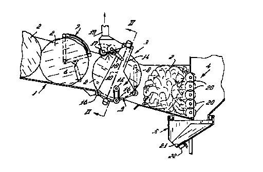
Figure 1 is a schematic side view of an implement
according to the invention, and
Figure 2 is a schematic cross-section of the implement
of Figure 1 according to the arrows II - II.
Figure 1 shows schematically a side view of an
implement according to the invention. The implement comprises a
sloping supply channel 1 for wrapped (e. g. cylindrical) feed
bales 2, means 3 for removing the wrapper from a feed bale 2,
means 4 for bringing fodder out of the feed bale 2 into a form
which is suitable for consumption, and means 5 for supplying the
fodder which has been brought into a consumable form to a
feeding stall (non-shown and known per se) for the animals to be
fed.
The supply channel 1 is provided with an element 7 in
the shape of a cylinder casing segment for supplying each time
one feed bale 2 to the means 3 for removing the wrapper from a
feed bale 2, said element 7 being pivotable by means of a
control element 6. The control element 6 may be constituted by a
hydraulic cylinder, one end of which is connected with the

CA 02321249 2000-08-14
WO 00/38503 PCT/NL99/00758
2
supply channel 1 and whose other end is connected with the
element 7. By reciprocating the cylinder 6 (to be operated
manually or automatically, e.g. in a computer-controlled
manner ) , the element 7 can be pivoted between a first position,
shown in Figure 1, in which the most right hand one of the bales
2 in the supply channel 1 is stopped, and a second position, in
which the most right hand feed bale 2 is released, so that the
latter is allowed to roll into the means 3 for removing the
wrapper from a feed bale 2. In the second position of the
element 7, the other bales 2 in the supply channel 1 are
stopped. When the element 7 is pivoted back into the first
position, the other bales 2 in the supply channel 1 move up to
the right.
The means 3 for removing the wrapper from a feed bale 2
are provided with a floor element 9, which can be tilted by
means of a further control element 8 for receiving each time one
wrapped feed bale 2 and supplying same, after the wrapper has
been removed therefrom, to the means 4 for bringing fodder out
of the feed bale 2 into a form which is suitable for
consumption. The control element 8 may be constituted by a
hydraulic cylinder, one end of which is rigidly connected with
the implement and whose other end is connected with the floor
element 9. By reciprocating the cylinder 8 (to be operated
manually or automatically, e.g. in a computer-controlled
manner), the element 9 can be tilted between a first position
shown in Figure 1, in which the bale 2 is stopped, and a second
position, in which the bale 2 is released, so that the latter is
allowed to roll into the means 4 for bringing fodder out of the
feed bale 2 into a form which is suitable for consumption. When
the element 9 is tilted back into the first position, a next
bale 2 can be received from the supply channel 1.
The means 3 for removing the wrapper from a feed bale 2
are provided with means for cutting the wrapper. This will be
explained in further detail in the following with reference to
Figure 2 showing schematically a cross-section of the implement

CA 02321249 2000-08-14
WO 00/38503 PCT/NL99/00758
3
of Figure 1 according to the arrows II - II. A cutting element
10, which can be put under tension against the wrapper of the
feed bale 2 or around the wrapper of the feed bale 2, extends
for the greater part around the feed bale 2. For that purpose,
the cutting element 10, e.g. a cutting thread, is connected at
one end with a first motor 11 and at the other end with a second
motor 12. At the corners of the bale 2 the cutting thread 10
makes each time a bend. At these points the cutting thread is
suspended from a framework 14 via spring elements 13. The motors
l0 11, 12 are able to put the thread 10 under tension against
spring action of the spring elements 13. With the aid of the
spring elements 13, the cutting thread 10 comes loose from the
bale 2 after cutting. In an embodiment of the invention, the
cutting thread 10 may be connected with (non-shown) means for
heating the cutting thread 10. This has a favourable influence
on the cutting process. This can also be achieved by
reciprocating the cutting element 10, e.g. with the aid of the
motors 11 and 12.
In the embodiment shown in Figure 1, the means 3 for
removing the wrapper from a feed bale 2 are provided with means
for rotating the feed bale 2, e.g. constituted by rollers 16
that are driven with the aid of a motor 15. Especially in the
case of cylindrical bales 2, the removal of the wrapper can be
facilitated by rotating the bate 2.
The means 3 for removing the wrapper from a feed bale 2
are further provided with means for stripping the wrapper from
the feed bale 2. The latter means comprise two cylindrical
rollers 17, which are almost touching each other and which are
rotatable in opposite directions. The wrapper cut loose from a
bale 2 is gripped by these rollers 17 and stripped from the bale
2 while the latter is rotating. The rollers 17 may be fitted to
the framework 14 in such a manner that they can be pivoted away
with the aid of a cylinder 18, so as not to impede a feed bale 2
rolling out of the supply channel 1. Finally the means 3 for
removing the wrapper from a feed bale are provided with a device

CA 02321249 2000-08-14
WO 00/38503 PCT/NL99/00758
4
for discharging the wrapper, e.g. constituted by an extractor
hood 19 disposed in the vicinity of the rollers 17.
The means 4 for bringing fodder out of the feed bale 2
into a form which is suitable for consumption comprise a row of
co-operating cutting elements 20 which are known per se. In a
further, non-shown embodiment, the means 4 for bringing fodder
out of the feed bale 2 into a form which is suitable for
consumption comprise a number of rotatable knives or rotatable
cutters. If desired, the bale 2 can be orientated into a
l0 position which is advantageous for cutting fodder.
The means 5 for supplying the fodder that has been
brought into a consumable form to the feeding stall comprise a
controllable nozzle 21. With the aid of said nozzle 21 (to be
rotated or translated manually or automatically, e.g. by means
of a computer), the fodder may be distributed among various
(non-shown) feeding troughs. The nozzle may be provided with
means for intercepting substances in the fodder that are unfit
for consumption, such as particles consisting of metal. The
latter means may comprise a magnet 22 (or an electromagnet or a
reel). Because of the fact that the magnet 22 is directly fitted
to the nozzle 21, the disturbing particles can be removed
efficiently.
It is remarked that the device for removing the wrapper
from a wrapped bale 2 may be used per se also independently of
the feeding implement described and for other applications and
types of bales.
The entire implement (and also parts thereof) may be
controlled automatically (e.g. with the aid of a computer or
another control unit) or manually. Furthermore, the entire
3o implement (and also parts thereof) may be designed movably.

Dessin représentatif
Une figure unique qui représente un dessin illustrant l'invention.
États administratifs

2024-08-01 : Dans le cadre de la transition vers les Brevets de nouvelle génération (BNG), la base de données sur les brevets canadiens (BDBC) contient désormais un Historique d'événement plus détaillé, qui reproduit le Journal des événements de notre nouvelle solution interne.

Veuillez noter que les événements débutant par « Inactive : » se réfèrent à des événements qui ne sont plus utilisés dans notre nouvelle solution interne.

Pour une meilleure compréhension de l'état de la demande ou brevet qui figure sur cette page, la rubrique Mise en garde , et les descriptions de Brevet , Historique d'événement , Taxes périodiques et Historique des paiements devraient être consultées.

Historique d'événement

Description Date
Inactive : CIB de MCD 2006-03-12
Demande non rétablie avant l'échéance 2005-12-12
Le délai pour l'annulation est expiré 2005-12-12
Inactive : Abandon.-RE+surtaxe impayées-Corr envoyée 2004-12-10
Réputée abandonnée - omission de répondre à un avis sur les taxes pour le maintien en état 2004-12-10
Lettre envoyée 2002-08-28
Inactive : Lettre officielle 2002-03-22
Inactive : Grandeur de l'entité changée 2001-12-05
Inactive : Page couverture publiée 2000-11-28
Inactive : CIB en 1re position 2000-11-22
Lettre envoyée 2000-11-03
Inactive : Notice - Entrée phase nat. - Pas de RE 2000-11-03
Demande reçue - PCT 2000-10-31
Demande publiée (accessible au public) 2000-07-06

Historique d'abandonnement

Date d'abandonnement Raison Date de rétablissement
2004-12-10

Taxes périodiques

Le dernier paiement a été reçu le 2003-11-21

Avis : Si le paiement en totalité n'a pas été reçu au plus tard à la date indiquée, une taxe supplémentaire peut être imposée, soit une des taxes suivantes :

  • taxe de rétablissement ;
  • taxe pour paiement en souffrance ; ou
  • taxe additionnelle pour le renversement d'une péremption réputée.

Veuillez vous référer à la page web des taxes sur les brevets de l'OPIC pour voir tous les montants actuels des taxes.

Historique des taxes

Type de taxes Anniversaire Échéance Date payée
Enregistrement d'un document 2000-08-14
Taxe nationale de base - petite 2000-08-14
TM (demande, 2e anniv.) - générale 02 2001-12-10 2001-11-21
Enregistrement d'un document 2002-01-14
Enregistrement d'un document 2002-08-30
TM (demande, 3e anniv.) - générale 03 2002-12-10 2002-11-21
TM (demande, 4e anniv.) - générale 04 2003-12-10 2003-11-21
Titulaires au dossier

Les titulaires actuels et antérieures au dossier sont affichés en ordre alphabétique.

Titulaires actuels au dossier
LELY ENTERPRISES AG
Titulaires antérieures au dossier
KAREL VAN DEN BERG
Les propriétaires antérieurs qui ne figurent pas dans la liste des « Propriétaires au dossier » apparaîtront dans d'autres documents au dossier.
Documents

Pour visionner les fichiers sélectionnés, entrer le code reCAPTCHA :


Pour visualiser une image, cliquer sur un lien dans la colonne description du document. Pour télécharger l'image (les images), cliquer l'une ou plusieurs cases à cocher dans la première colonne et ensuite cliquer sur le bouton "Télécharger sélection en format PDF (archive Zip)" ou le bouton "Télécharger sélection (en un fichier PDF fusionné)".

Liste des documents de brevet publiés et non publiés sur la BDBC .

Si vous avez des difficultés à accéder au contenu, veuillez communiquer avec le Centre de services à la clientèle au 1-866-997-1936, ou envoyer un courriel au Centre de service à la clientèle de l'OPIC.


Description du
Document 
Date
(aaaa-mm-jj) 
Nombre de pages   Taille de l'image (Ko) 
Dessin représentatif 2000-11-28 1 16
Page couverture 2000-11-28 1 48
Abrégé 2000-08-14 1 51
Description 2000-08-14 4 208
Revendications 2000-08-14 3 141
Dessins 2000-08-14 1 29
Avis d'entree dans la phase nationale 2000-11-03 1 195
Courtoisie - Certificat d'enregistrement (document(s) connexe(s)) 2000-11-03 1 113
Rappel de taxe de maintien due 2001-08-13 1 116
Rappel - requête d'examen 2004-08-11 1 117
Courtoisie - Lettre d'abandon (taxe de maintien en état) 2005-02-07 1 175
Courtoisie - Lettre d'abandon (requête d'examen) 2005-02-21 1 166
PCT 2000-08-14 4 163
Correspondance 2002-03-22 1 21