Note : Les descriptions sont présentées dans la langue officielle dans laquelle elles ont été soumises.
CA 02321281 2000-08-17
WO 99/4186 PCT/US99103581
-1-
FIBER OPTIC ATTENUATORS AND ATTENUATION SYSTEMS
The present invention relates to controllable attenuators and
attenuation systems for attenuating optical energy transmitted through a fiber
optic.
Back~gf the Lnve_ntion
There is often a requirement in fiber optic systems for precise control
of optical signal levels entering various system components. This is
particularly true for systems at test and characterization stages of
deployment.
A controllable optical attenuator can be used, for example, to characterize
and
optimize the optoelectronic response of high-speed photoreceivers, wherein
the detection responsivity is dependent on the average optical power incident
on the photodiode.
The majority of controllable fiber optic attenuators currently
15 commercially available rely on thin-film absorption filters. This requires
breaking the fiber and placing the filters in-line. Controllable attenuation
is
then achieved by mechanical means such as rotating or sliding the filter to
change the optical path length within the absorptive material. This adversely
impacts the response speed of the device, the overall mechanical stability,
zero
attenuation insertion loss and optical back reflection. In general, broken
fiber
designs suffer numerous disadvantages such as high insertion loss, significant
back reflection, and large size. These factors can be minimized, although such
corrective measures typically result in added cost andlor size.
CA 02321281 2000-08-17
WO 99/42867 PCT/US99/03581
-2-
What is required are improved controllable fiber optic attenuators and
attenuation systems which keep the optical fiber core intact and which achieve
controllable attenuation via control of radiative loss from the fiber.
Summary of the Invention
5 The present invention relates to controllable fiber optic attenuators
(e.g., variable optical attenuators "VOAs") and attenuation systems, designed
to operate in the conventional telecommunication spectral windows of 1300
nm and 1550 nm, or any other wavelengths of interest, especially those at
which single mode propagation occurs. The devices can be placed in fiber
10 optic networks or systems by simple fusion splicing or connectorization to
attenuate optical signal levels by a desired amount. Controllable attenuation
is
achieved, for example, by thermal or electrical control of controllable
material
layers. The devices can be used for controllable attenuation in fiber optic
systems at the test and characterization stage, or for active control during
15 operational deployment.
The side-polished fiber ("SPF") devices of the present invention are an
improvement over conventional broken fiber approaches because of their
intrinsic fiber continuity.
In a first embodiment of a controllable attenuator of the present
20 invention, a fiber is mounted in a block and polished to within a close
proximity (e.g., a few microns) of the core. A controllable bulk material,
with
an approximately matched refractive index (to the effective fiber mode index)
is applied over the polished surface. Adjusting the index of refraction of the
bulk material (e.g., via the electro- or thermo-optic effect), results in a
25 controllable amount of optical energy extracted from the fiber optic, thus
achieving controllable attenuation.
CA 02321281 2000-08-17
WO 99/42867 PCT/US99103581
-3-
An attenuation system, including a controllable attenuator, is also
disclosed in which a control circuit applies a changeable stimulus to the
controllable material, in accordance with a desired level stimulus, and/or a
sensed level stimulus received from a sense circuit coupled to the fiber optic
5 for sensing a level of optical energy being transmitted therein.
In an improved embodiment of the controllable attenuator of the
present invention, the fiber is polished through its cladding almost to its
core,
and a thin controllable material is placed between the fiber and a high-index,
bulk overlay material. The index of refraction of the controllable material
10 (approximately matched to that of the cladding) is varied, which
effectively
varies the effective aptical thickness (index x actual thickness) of the
remaining cladding. This improved, cladding-driven ("CD") controllable
attenuator provides nearly spectrally flat optical attenuation in the
wavelength
ranges of interest, while retaining all of the intrinsic advantages of the SPF
15 architecture. Moreover, a design is disclosed where the typically used
radius
block holding the fiber is eliminated, which allows the device to be reduced
in
size so that it is not much larger than the fiber itself.
In that regard, the present invention relates to, in its first embodiment,
an attenuation system for attenuating optical energy being transmitted through
20 a fiber optic. A controllable attenuator is arranged with respect to a
portion of
the fiber optic having material removed therefrom thereby exposing a surface
thereof through which at least some of the optical energy can be controllably
extracted. The attenuator includes a controllable material formed over the
surface for controllably extracting the optical energy according to a
changeable
25 stimulus applied thereto which affects the refractive index thereof. A
level
sensing circuit may be coupled to the fiber optic for sensing a level of at
least a
portion of the optical energy transmitted therein and providing a sensed level
stimulus to a control circuit, which is coupled to the controllable attenuator
for
CA 02321281 2000-08-17
WO 99/42867 PCTNS99/03581
applying the changeable stimulus to the controllable material thereof in
accordance with the sensed level stimulus received from the level sensing
circuit.
The changeable stimulus applied to the controllable material may be,
5 for example, temperature (thermo-optic effect) or voltage (electro-optic
effect).
In a second, improved aspect, the present invention relates to a
cladding-driven ("CD") controllable attenuator for attenuating optical energy
transmitted through a fiber optic. The controllable attenuator is arranged
with
respect to a portion of the fiber optic having material removed therefrom
10 thereby exposing a surface thereof through which at least some of the
optical
energy being transmitted therein can be extracted. The controllable attenuator
includes a controllable material formed over the exposed surface for
controlling an amount of optical energy extracted from the fiber optic
according to a changeable stimulus applied to the controllable material which
15 affects the index of refraction thereof. In addition, a bulk material layer
formed over the controllable material is provided into which the extracted
optical energy is radiated.
In this embodiment, the controllable material has a controllable index
of refraction approximately matching the index of the cladding, and the bulk
20 material formed over the controllable material has a fixed index of
refraction
higher than the effective mode index of the fiber optic.
The controllable fiber optic attenuators and attenuation systems of the
present invention are valuable in any applications where control of the
optical
power transmission in an optical fiber is required. The attenuators are
25 especially useful in applications where the spectral flatness of
attenuation is a
concern. Because of the fiber continuity, these devices exhibit the intrinsic
CA 02321281 2000-08-17
WO 99/42867 PCTIUS99/03581
-5-
benefits of low insertion loss, low back reflection (high return loss),
polarization insensitivity, small size, low cost, and mass pmduceability.
Brief Description of the Drawings
The subject matter which is regarded as the invention is particularly
5 pointed out and distinctly claimed in the concluding portion of the
specification. The invention, however, both as to organization and method of
practice, together with further objects and advantages thereof, may best be
understood by reference to the following detailed description of the preferred
embodiments) and the accompanying drawings in which:
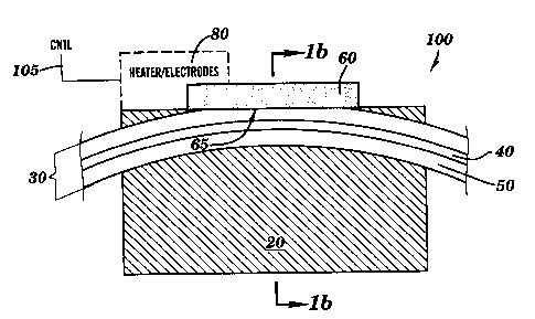
10 Fig. la is a side, cross-sectional view of a first
embodiment of a controllable fiber optic attenuator in
accordance with the present invention;
Fig. lb is an end cross-sectional view of the
controllable attenuator of Fig. la;
15 Figs. 2a-b are graphs (in percentage, and decibels,
respectively) depicting the loss characterization versus the
refractive index of a bulk (e.g., liquid) overlay for three
exemplary levels of fiber side-polishing;
Fig. 3a is a detailed view of the material interfaces of
20 the controllable attenuator of Figs. la-b, and further depicts an
exemplary mode profile of the optical energy being transmitted
in the fiber optic;
CA 02321281 2000-08-17
WO 99/42867 PCTNS99103581
Fig. 3b is a detailed view of the material interfaces of a
second, cladding-driven embodiment of a controllable fiber
optic attenuator of the present invention;
Figs. 4a-b are respective graphs of the spectral
5 performance of the controllable attenuators of Figs. 3a-b;
Fig. 5 is a graph of resultant attenuation versus the
superstrate refractive index of side-polished fiber attenuators,
and depicts the respective operating ranges of the controllable
attenuators of Figs. 3a-b;
10 Fig. 6a is a side, cross-sectional view of the second,
cladding-driven controllable attenuator of Fig. 3b;
Fig. 6b is a side, cross-sectional view of an
improvement to the cladding-driven controllable attenuator of
the present invention wherein the cladding is removed from the
15 fiber optic without a radial mounting in a substrate block;
Fig. 7 is a functional block diagram of an exemplary
attenuation system in accordance with the present invention;
and
Fig. 8 is an exemplary schematic of the attenuation
20 system of Fig. 7.
CA 02321281 2000-08-17
WO 99/42867 PCT/US99I03581
_'j_
Detailed Description of the Preferred Embodimentls)
In accordance with the principles of the present invention, a first
embodiment 100 of a controllable attenuator is depicted in Figs. la-b, in
which a single-mode optical fiber 30 (e.g., telecommunications Corning
5 SMF-28) is side-polished through its cladding 50 close to its core 40,
thereby
exposing, through surface 65, an evanescent tail of the optical energy
transmitted in the fiber. Typically, the remaining cladding thickness is <
about
l0,um. Optical energy can be extracted from the fiber core by application of a
bulk material 60 over the polished surface 65 of the fiber cladding. The bulk
10 material should have a refractive index slightly less than or approximately
equal to that of the fiber's effective mode index n~f. This value is dependent
upon the fiber core and cladding indices, and the fiber core dimensions, but
usually lies between the core and cladding indices. Maximum optical energy
is extracted from the fiber when the index of the bulk material matches the
15 fiber's effective mode index.
In accordance with the present invention, and as discussed in greater
detail below, the bulk material may be formed from a material which is
controllable, e.g., its index of refraction can be varied according to a
changeable stimulus applied thereto. In the embodiment of Fig. la,
20 temperature or voltage changes can be used, and a controllable heating
element
(or electrodes) 80 is provided, for providing a changeable temperature (or
voltage) stimulus to material 60 in accordance with a control stimulus 105.
Discussed below are first, the fabrication of the side-polished fiber
portion of attenuator 100 and its subsequent loss characterization; second,
25 alternate embodiments 100' and 100"' of a controllable attenuator; and
finally,
the implementation of an attenuation system including the controllable
attenuator 100 (or 100' or 100"), in addition to other control sub-systems.
CA 02321281 2000-08-17
WO 99/42867 PCT/US99/03581
_g-
Side-Polished Fiber Fabrication/Characterizatiow
Standard single-mode fibers have an 8.3um diameter core region 40 of
slightly raised refi~active index surrounded by a 125 t l~cm fused silica
cladding 50. The mode field diameter is 9.3 ~ 0.5,um at 1310 nm and 10.5 ~
0.5~cm at 1550 nm. The refractive index values supplied by Corning for
SMF-28 fiber are:
~. = 1300 nm: ri~re =1.4541, n~~~ = 1.4483
~, =1550 nm: x~~ =1.4505, n~,,d =1.4447
The small difference between the core and cladding refractive indices
combined with the small core size results in single-mode propagation of
optical energy with wavelengths above 1190 nm. Therefore, the fiber can be
used in both spectral regions although it was designed for 1310 nm operation
where dispersion (combination of material and waveguide dispersion) is
minimized and attenuation is low (<0.4dB/km).
The side-polished fiber controllable attenuator of Figs. la-b may be
fabricated by lapping and polishing techniques. The fiber is embedded in a
fused silica substrate block 20 containing a controlled radius groove.
Material
is carefully removed from the fiber cladding 50 until the core 40 is
approached. At this point, the evanescent field of the optical energy
transmitted in the optical fiber can be accessed through surface 65. The
device
interaction length can be controlled by the remaining cladding thickness and
the groove's radius of curvature.
Once the fiber core has been approached via the lapping/polishing
process, a multiple liquid-drop procedure may be performed to characterize the
loss of the side-polished fiber. This procedure involves placing a series of
CA 02321281 2000-08-17
WO 99/42867 PCT/US99/03581
-9-
bulk overlays (e.g., liquids, oils) of known refractive index onto the
polished
surface of the fiber. This has the advantage that the interface between the
oil
and the side-polished fiber is always as good as the fiber surface and there
is
no need to treat the surface/oil interface in any special way.
A set of Cargille Refractive Index Liquids is available with
well-characterized refractive indices and dispersion curves. Thus, an accurate
loss/refractive index characterization of each fabricated side-polished fiber
can
be obtained. Each liquid used in the measurements has a specified nD value,
where subscript D denotes the Sodium D-Line wavelength (~, = 589 nrn).
Dispersion equations are available which allow the response to be adjusted to
the spectral region of interest i.e. 1300 nm or 1550 nm. Figs. 2a-b show the
optical energy hansmission in percentage and decibels, respectively, versus
the
liquid's refractive index response for three side-polished fibers which each
have different remaining cladding thicknesses (i.e., 24%, 65% and 91%
polished cladding levels). At liquid indices below the fiber mode effective
index (n~f), no optical power is removed from the fiber. Close to n~~, the
transmission response drops sharply and strong extraction is observed. Above
n~, the fiber transmission gradually approaches a set level of attenuation.
Prior to any cladding removal, the fiber guides light efficiently. When
part of the cladding is removed, a new cladding exists which is composed of a
small thickness of fused silica surrounded by air (n=1). Since this composite
cladding has an effective cladding index less than that of the core, the fiber
can
still operate efficiently as a waveguide. This is true for those overlays
having
indices less than the fiber mode effective index, and 100% optical energy
transmission therefore occurs. However, when the liquid index is raised above
n~t, the fiber operates as a leaky waveguide and a bulk wave is excited in the
liquid. Thus, power is leaked from the fiber within the interaction region and
a
certain attenuation occurs. The efficiency of coupling to the bulk wave is
CA 02321281 2000-08-17
WO 99/42867 PCT/US99/03581
-10-
maximum when the liquid's index matches the fiber mode effective index ne f.
This efficiency is reduced when the liquid's index is increased above n~~,
although a significant fraction of power is still coupled out of the fiber.
Transmission measurements can be made using Fabry-Perot Diode
5 Lasers at 1300 nm and 1550 nm and a well-calibrated Optical Power Meter.
Stronger attenuation figures are observed for the same liquid index at 1550 nm
since the evanescent penetration of the fiber mode field into the cladding is
greater at the longer wavelength.
In accordance with the present invention, as discussed above, a bulk
10 material 60 is applied over the exposed surface of the side-polished fiber
optic.
The bulk material 60 is, for example, a controllable polymer (e.g., electro-
optic or thermo-optic) with an index of refraction closely matched to the
effective mode index of the fiber, and which exhibits a change in refractive
index proportional to a change in, e.g., temperature or voltage. OPTI-CLAD~
15 I45 available from Optical Polymer Research, Inc. is an example of such a
polymer. A controllable attenuator (100, Figs. la-b) is therefore formed
capable of extracting a controllable amount of optical energy from the fiber.
Control of the attenuation is provided by heating element (or electrodes) 80
controlled using a control stimulus 105.
20 To achieve the maximum thermo-optic responsivity, for example, the
controllable attenuator is implemented to exploit the most sensitive
characteristic refractive index response of the side-polished fiber,
determined
as set forth above. This occurs when the refractive index of the bulk material
is slightly less than the effective mode index of the optical fiber (e.g.,
n~f=
25 1.449), i.e., proximate the vertical lines 99 drawn on the graphs of Figs.
2a-b.
These lines 99 therefore describe in general the theoretical operating range
of
this first embodiment of a side-polished fiber controllable attenuator.
CA 02321281 2000-08-17
WO 99/42867 PCT/US99/03581
-11-
Alternate Controllable Attenuatar Embodiments:
One aspect of the above-discussed controllable attenuator embodiment
100 is that the level of attenuation may vary with wavelength, which may
cause design problems for multi-wavelength transmission systems.
S In accordance with the present invention, an improved, cladding-driven
("CD") side-polished fiber controllable attenuator is disclosed which improves
spectral performance while retaining all of the intrinsic performance
strengths
of non-invasive, side-polished fiber devices.
Figs. 3a-b respectively depict in detail the material interfaces of the
10 bulk overlay controllable attenuator 100 discussed above, and the improved,
cladding-driven controllable attenuator 100' of the present invention. With
reference to Fig. 3a, controllable attenuator 100 includes a fiber core 40, a
remaining portion of cladding 50 (thickness C~" e.g., < about l0~cm) having an
exposed surface 65 thereof through which optical energy is extracted into
15 controllable bulk material 60. A mode profile 90 is also depicted
approximating the amount of optical energy present in the material layers,
including the evanescent tail 91 (the penetration of which into layer 60 is
controllable as set forth above).
The cladding-driven controllable attenuator 100' of Fig. 3b also
20 includes a fiber core 40', but remaining portion 50' of the cladding
(thickness
C~,', e.g., < about 2~cm) is a very thin layer and a thin film(e.g., thickness
about l0~cm) of controllable material 60' is positioned over cladding 50'. A
bulk material 70' is positioned over layer 60' and is a high index material.
Evanescent tail 91' of mode profile 90' penetrates through exposed surface 65'
25 into high index layer 70' at a depth determined by the effective optical
thickness (index x actual thickness) of controllable material 60', which has
an
CA 02321281 2000-08-17
WO 99/4?,867 PCTIUS99/03581
-12-
index approximately matched to that of the cladding. This effective optical
thickness of layer 60' (index x actual thickness) is controlled by varying the
refractive index thereof according to the techniques discussed above, e.g.,
thermo-optic or electro-optic effects.
The most significant differences between the cladding-driven
embodiment 100' and the controllable bulk material embodiment 100 are: (i)
most of the fiber cladding is initially removed (on the polished side) and
replaced with a cladding index matched, but controllable thin layer of
material
60' (e.g. a thermo-optic polymer having an index of about 1.447 at 1300 nm)
IO and (ii) the bulk overlay 70' is of higher index, for example, silicon,
with an
index of about 3.5.
As shown in the graphs of Figs. 4a-b, which respectively represent the
spectral performance of controllable attenuator embodiments 100 and 100',
these improvements result in a better spectral uniformity. The reasons for
this
spectral uniformity can be understood by referring to the respective operating
ranges 99 and 99' of the attenuation graph of Fig. 5. The attenuation of a
side-
polished fiber device is a sensitive function of both: {i) the remaining
cladding
thickness; and (ii) the index of any overlay material. In the first embodiment
of controllable attenuator 100, a significant portion of the evanescent tail
of the
fiber mode profile propagates within the remaining cladding. Therefare to
achieve significant attenuation, the side-polished fiber is overlaid with a
bulk
material 60 which has a refi~active index which lies close to the effective
fiber
mode index, n~f Adjusting the bulk material index produces an attenuation
transfer function which follows the very sharp edge of the attenuation
response
curve, i.e., proximate vertical line 99.
CA 02321281 2000-08-17
WO 99/42867 PCT/US99/03581
-13-
However, because this edge is so sharp, the amount of attenuation is
very sensitive to variations in the fiber mode profile. Therefore, effects
such
as dispersion (changes in refractive index versus wavelength), can result in
wavelength dependent performance. Another, perhaps more significant effect
occurs simply because the fiber mode itself is larger at long wavelengths.
This
results in increased evanescent penetration into the overlay, and thus higher
attenuation.
The cladding-driven controllable attenuator embodiment 100'
eliminates these effects because its operation is based on an entirely
different
transfer function. As shown toward the right side of Fig. 5, the cladding-
driven approach adjusts the effective optical thickness of the remaining
cladding using the controllable, cladding index-matched layer 60', and
therefore changes the amount of evanescent tail 91' penetration into bulk
material 70', which has a fixed, high index: The attenuation is therefore much
less sensitive to variations in the refractive index of the bulk material when
that index lies far above n~.. The cladding-driven device therefore operates
along vertical line 99' toward the right side of Fig. 5. This has been shown
to
produce attenuation levels which are nearly independent of wavelength (Fig.
4b), and therefore improves the spectral uniformity of the device.
The index insensitivity of the bulk material 70' also implies that for a
given amount of remaining fiber cladding (which determines the amount of
attenuation at high index for a given interaction length), varying the index
of
the bulk material 70'(e.g through the therma-optic effect) will not
significantly
alter the amount of attenuation. Therefore the response of such a device
without a controllable cladding layer would be negligible.
CA 02321281 2000-08-17
WO 99/42867 PCT/US99/03581
-14-
The solution to this apparent impasse was found by observing that the
amount of attenuation (with a high index bulk material) is very sensitive to
the
amount of remaining thickness of fiber cladding; i.e., the more cladding
removed, the higher the resulting attenuation (as shown by the curves toward
5 the right side of Fig. S). Thus, if an SPF-based device is produced which
operates along the transfer function 99' toward the right side of Fig. 5, then
both high device responsivity and spectral flatness can be realized. The
cladding-driven controllable attenuator 100' achieves these results.
In the cladding-driven controllable attenuator 100', nearly all of the
10 original (silica) fiber cladding is removed (typically by polishing,
although
chemical etching is possible). This would normally result in a > 99 % (> -20
dB) high index overlay coupler. However, the removed cladding is replaced
with a thin film of controllable material 60' (similar in thickness to the
evanescent penetration depth) which has a similar (fiber cladding matched)
15 ambient refractive index. Further, the refractive index of this material is
much
more responsive to an applied signal (e.g. thermo-optic: heat, or electro-
optic:
voltage), than that of the original silica cladding. On top of this thin
layer, a
high index bulk material 70' is applied to preserve spectral flatness, as
discussed above.
20 Under ambient conditions, a device with very low attenuation results.
However, by applying a changeable stimulus to the "replacement" cladding
layer 60' which raises its index (up to that of the effective mode index), the
evanescent mode penetration through this "replacement" cladding layer 60'
can be varied, and therefore the depth of its penetration into the high index
25 bulk overlay 70', effecting controllable attenuation. Removing the stimulus
reduces the refractive index of the replacement cladding layer 60', which
restores low loss transmission. Any induced variations in the refractive index
of the bulk material 70' are negligible because of the intrinsic insensitivity
of
CA 02321281 2000-08-17
WO 99/42867 PCTNS99/03581
-15-
the device to this parameter. Thus, the cladding-driven controllable
attenuator
100' simultaneously achieves high responsivity and spectral flatness, as well
as low insertion loss, low back reflection, small size, and low loss
characteristics of SPF-based devices, all of which make this embodiment
5 highly attractive.
Side, cross-sectional views of two potential embodiments (100' and
100") of cladding-driven controllable attenuators are shown in Fig. 4b. The
embodiment of Fig. 4a, discussed generally above, is a design based on the
typical SPF radius groove block, wherein the radius of the fiber, upon its
10 polishing, results in a flat surface 65' though which optical energy can be
extracted. Fig. 4b depicts an alternative blackless design 100" which is
fabricated by removing material to produce a radial surface 65", over which
controllable material 60" and bulk material 70" are conformably formed, up to
the outer diameter of the fiber. Cladding 50" remains (thickness Ct,," of <
15 about 2,um). Elimination of the SPF block in the design 100" allows the
device to be reduced in size, so that it is not much larger than the fiber
itself.
Those skilled in the art will recognize that embodiment 100 discussed
above can also be fabricated using this blockless design.
Attenuation Svstem(sl Employin Controllable Attenuators:
20 An exemplary attenuation system S00 employing controllable
attenuator 100 (or 100' or 100") is shown in Fig. 7. The attenuation system
500 includes a controllable attenuator 100 (or 100' or 100"), a control
circuit
300, and an optional level-sense circuit 200. Control circuit 300 supplies
control stimulus 105 to the controllable attenuator 100 to change the
25 changeable stimulus (temperature or voltage) and therefore the refractive
index
of the controllable material thereof. Control circuit 300 receives as an
optional
input a desired level stimulus 305 from, for example, a user, and adjusts the
CA 02321281 2000-08-17
WO 99/42867 PCT/US99/03581
-16-
control stimulus 105 as a function thereof. Control circuit 300 may also
receive an optional sensed level stimulus from level sense circuit 20U. This
sensed level stimulus can be, for example, a ratio of measured levels of
optical
energy both prior to and following the attenuation thereof by the attenuator
5 100. By comparing this sensed level stimulus to the desired level stimulus,
control circuit 300 can vary the value of control stimulus 105 until the input
desired level stimulus and sensed level stimulus are matched.
Exemplary attenuation system 500 is depicted in an exemplary
schematic form in Fig. 8. The controllable attenuator 100 is preceded and
10 followed by 1 % fiber couplers (splitters 210, 230) which tap a small
fraction
of the optical power propagating in the fiber. The decoupled light is carried
to
characterized photodetectors (220, 240) and the generated photocurrents are
analyzed by a ratiorneter 250. Comparator circuit 310 receives the sensed
level stimulus output of the ratiometer and/or a desired level stimulus 305
15 (from a user) and transmits a signal to the temperature controller 320. The
temperature controller provides the control stimulus 105 to controllable
attenuator 100 to change the changeable stimulus (temperature or voltage) and
therefore the refractive index of the controllable material thereof. In this
way,
the optical attenuation level (photocurrent ratio) is directly compared to a
20 calibrated attenuation adjustrnent signal 305 (user or system input) until
they
are matched. This feedback loop controls the attenuation effected by the
controllable attenuator and therefore ensures accurate performance.
The present invention also extends to the methods for forming and
using the disclosed controllable attenuators and attenuation systems, and
25 further to methods for attenuation, discussed above.
CA 02321281 2000-08-17
WO 99142867 PCT/US99/03581
-17-
Those skilled in the art will also recognize that the present invention
extends to i.) fixed set point attenuators wherein, under controlled ambient
conditions, the controllable material layers are designed with a predetermined
refractive index such that a predetermined, fixed level of attenuation
results,
5 thereby negating the need for a changeable stimulus applied to the
controllable
material, and ii.) adaptive attenuation wherein a fixed attenuation level is
desired, and the changeable stimulus is adaptively applied to the controllable
material as a function of changing ambient conditions which unintentionally
affect the refractive index of the controllable material.
10 While the invention has been particularly shown and described with
reference to preferred embodiments) thereof, it will be understood by those
skilled in the art that various changes in form and details may be made
therein
without departing from the spirit and scope of the invention.