Sélection de la langue

Search

Sommaire du brevet 2321575 

Énoncé de désistement de responsabilité concernant l'information provenant de tiers

Une partie des informations de ce site Web a été fournie par des sources externes. Le gouvernement du Canada n'assume aucune responsabilité concernant la précision, l'actualité ou la fiabilité des informations fournies par les sources externes. Les utilisateurs qui désirent employer cette information devraient consulter directement la source des informations. Le contenu fourni par les sources externes n'est pas assujetti aux exigences sur les langues officielles, la protection des renseignements personnels et l'accessibilité.

Disponibilité de l'Abrégé et des Revendications

L'apparition de différences dans le texte et l'image des Revendications et de l'Abrégé dépend du moment auquel le document est publié. Les textes des Revendications et de l'Abrégé sont affichés :

  • lorsque la demande peut être examinée par le public;
  • lorsque le brevet est émis (délivrance).
(12) Demande de brevet: (11) CA 2321575
(54) Titre français: DISPOSITIF DE FIXATION DE MATELAS
(54) Titre anglais: MATTRESS SECURING DEVICE
Statut: Réputée abandonnée et au-delà du délai pour le rétablissement - en attente de la réponse à l’avis de communication rejetée
Données bibliographiques
(51) Classification internationale des brevets (CIB):
  • A47C 19/00 (2006.01)
  • A47C 21/02 (2006.01)
  • A47C 31/00 (2006.01)
(72) Inventeurs :
  • PERKINS, MARK R. (Etats-Unis d'Amérique)
  • WINKEL, BRANDON J. (Etats-Unis d'Amérique)
(73) Titulaires :
  • MARK R. PERKINS
  • BRANDON J. WINKEL
(71) Demandeurs :
  • MARK R. PERKINS (Etats-Unis d'Amérique)
  • BRANDON J. WINKEL (Etats-Unis d'Amérique)
(74) Agent: BORDEN LADNER GERVAIS LLP
(74) Co-agent:
(45) Délivré:
(86) Date de dépôt PCT: 1999-03-04
(87) Mise à la disponibilité du public: 1999-09-10
Licence disponible: S.O.
Cédé au domaine public: S.O.
(25) Langue des documents déposés: Anglais

Traité de coopération en matière de brevets (PCT): Oui
(86) Numéro de la demande PCT: PCT/US1999/004835
(87) Numéro de publication internationale PCT: US1999004835
(85) Entrée nationale: 2000-08-28

(30) Données de priorité de la demande:
Numéro de la demande Pays / territoire Date
60/076,739 (Etats-Unis d'Amérique) 1998-03-04

Abrégés

Abrégé français

La présente invention concerne un lien (10) servant à retenir avec mobilité un matelas (18) sur un sommier (22). Ce lien (10) est assez long pour permettre de tirer le matelas (18) d'une première position selon laquelle il repose complètement sur le sommier (22) en une seconde position selon laquelle il pend en débord du sommier (22). En outre, le lien (10) est assez court pour retenir le matelas (18) dans la seconde position tout en l'empêchant de tomber totalement du sommier (22). Le lien permet au personnel mettant les draps sur le matelas (18), d'abord de tirer à soi le matelas (18) pour le tenir dans la seconde position et partant avoir un meilleur accès au bord opposé du matelas (18) pour mettre les draps, puis de repousser facilement le matelas (18) en première position une fois que les draps sont mis.


Abrégé anglais


A connector (10), for removably securing a mattress (18) to a mattress
supporting bed frame (22), that is provided a length that is sufficient to
allow one to pull the mattress (18) from a first position in which it is fully
supported on the supporting frame (22), to a second position in which it is
supported on an edge of the frame (22) and hangs out beyond the edge of the
supporting frame (22). The connector (10) is sufficiently short to retain the
mattress (18) in the second position and not allow the mattress (18) to fall
off the supporting frame (22). The connector (10) allows a person placing
sheets on the mattress (18) to pull the mattress (18) toward oneself into the
second position and thereby more easily reach the far edge of the mattress
(18) when placing sheets on it, and can then put the mattress (18) back into
the first position when the sheets are in place.

Revendications

Note : Les revendications sont présentées dans la langue officielle dans laquelle elles ont été soumises.


The invention claimed is:
1. A bed comprising:
a mattress supporting frame;
a mattress removably positioned on said supporting frame;
a connector secured to said frame and to said mattress;
said connector being a length which is sufficient to allow one to pull said
mattress
from a first position in which it is fully supported on said supporting frame,
to a second
position in which it is supported on an edge of said frame and hangs out
beyond said
edge of said supporting frame, said connector being sufficiently short to
retain said
mattress in said second position and not allow said mattress to fall off of
said supporting
frame;
whereby a person placing sheets and covers on said mattress can pull said
mattress toward himself or herself into said second position and thereby more
easily
reach the far edge of said mattress when placing sheets and covers on it, and
can then
push said mattress back into said first position when the sheets and covers
are in place.
2. The bed described in claim 1, wherein:
said connector is provided a first section and a second section wherein said
first
section secures said mattress and said second section is secured to said
frame.
The bed described in claim 2, wherein:
said connector includes at least one strap and at least one buckle, said first
section of said strap configured to form a loop section and said second
section of said
strap configured to form a leader portion wherein said loop secures said
mattress and
said leader portion is attached to said frame, said buckle slidably engaged
with said strap
and adapted to allow the operator to adjust the size of said loop formed by
said strap,
said leader portion of said strap is attached to said frame.
4. The bed described in claim 3, further including:
a mounting bracket connected to said leader portion of said strap, said
bracket
attached to said frame.
-6-

5. The bed described in claim 4, wherein:
said leader portion of said strap includes a first securing section, a second
securing section and a quick release connector wherein said first securing
section is
connected to said mounting bracket and said quick connector operably connects
said first
securing section to said second securing section whereby said quick connector
may be
disconnected allowing complete removal of said mattress from said frame.
6. The bed described in claim 5, wherein:
said quick connector is adapted to adjust the length of said leader portion,
whereby the distance said mattress may be removed from said bed is adjustable.
7. The bed described in claim 6, wherein:
said frame includes a mattress support extending below said mattress; and
said mounting bracket is connected to said frame and said first securing
section of
said strap extends across an underside of said mattress and said mattress
support and is
fixedly attached to said frame at a position substantially juxtaposed across
said mattress
from said mounting bracket, whereby said mattress and said mattress support
are
prevented from falling downward.
8. The bed described in claim 7, further including:
a second mounting bracket connected to said leader portion of said strap, said
bracket attached to said frame at a position substantially juxtaposed across
said mattress
from said first mounting bracket.
9. The bed described in claim 8, wherein:
said second securing section is fixedly attached to said mattress support.
10. The bed described in claim 9, wherein:
said mattress support includes at least two pieces.
11. The bed described in claim 10, wherein:
said at least one strap includes a first strap and a second strap.

12. The mattress-securing device described in claim 11, wherein:
said loop section of said first strap and said second strap are wrapped about
the
mattress.
13. The mattress-securing device described in claim 10, wherein:
said mattress includes at least one mattress handle, and said loop section of
said
first strap and said second strap are laced through said mattress handles such
that said
strap does not extend above said mattress.
14. The bed described in claim 1, wherein:
said connector includes a first section, a second section and a quick release
connector wherein said first section is connected to said frame, said second
section
secures said mattress and said quick connector operably connects said first
section to
said second section whereby said quick connector may be disconnected allowing
complete removal of said mattress from said frame.
15. The bed described in claim 1, wherein:
said connector is adapted to allow the operator to adjust the length of said
connector, whereby the distance said mattress may be removed from said bed
adjustable.
16. The bed described in claim 1, wherein:
said frame includes a mattress support extending below said mattress; and
said connector is connected to said frame at a first location and extends
across an
underside of said mattress and said mattress support and is fixedly attached
to said frame
at a second location substantially juxtaposed across said mattress from said
first location,
whereby said mattress and said mattress support are prevented from falling
downward.
17. The bed described in claim 16, wherein:
said mattress support includes at least two pieces.
18. The bed described in claim 1, wherein:
said mattress is secured to said frame by two said connectors equally spaced
along the length of the mattress.
-8-

19. The mattress-securing device described in claim 1, wherein:
said connector is secured about said mattress.
20. The mattress-securing device described in claim 1, wherein:
said mattress includes at least one mattress handle, and said connector is
laced
through said mattress handle such that said strap does not extend above said
mattress.
21. A kit for securing a mattress to a bed frame, comprising:
at least one strap configured to form a loop section adapted to secure a bed
mattress and a leader portion having a first securing section, a second
securing section
and a quick release connector wherein said first securing section is connected
to a
mounting bracket adapted to connect to a bed frame and said quick connector
operably
connects said first securing section to said second securing section whereby
said quick
connector may be disconnected thereby allowing complete removal of the
mattress from
the bed frame;
at least one buckle slidably engaged with said strap and adapted to adjust the
size
of said loop formed by said strap;
whereby the mattress may be partially removed from the bed frame thereby
providing easy access to the mattress for the purpose of changing bed linens
and the like.
22. The kit for securing a mattress to a bed frame described in claim 21,
wherein:
said quick connector is adapted to adjust the length of the leader portion,
whereby the distance the mattress may be removed from the bed frame may be
adjusted.
23. The kit for securing a mattress to a bed frame described in claim 22,
wherein:
said mounting bracket is adapted to connect to a rail of the bed frame and
said
first securing section of said strap is provided a sufficient length to extend
across an
underside of the mattress and any bed component supporting the mattress and is
adapted
to fixedly attach to the bed frame at a position substantially juxtaposed
across the
mattress from the mounting bracket, whereby the mattress and any bed component
supporting the mattress may be prevented from falling downward.
-9-

24. The kit for securing a mattress to a bed frame described in claim 23,
further
including:
a second mounting bracket adapted to connect to said leader portion of said
strap,
said second mounting bracket adapted to attach to the bed frame at a position
substantially juxtaposed across the mattress from the first mounting bracket.
25. The kit for securing a mattress to a bed frame described in claim 24,
wherein:
said second securing section is adapted to fixedly attached to the bed
components
supporting the mattress.
26. The kit for securing a mattress to a bed frame described in claim 25,
further
including:
a mattress support for supporting the mattress within the bed frame.
27. The kit for securing a mattress to a bed frame described in claim 26,
wherein:
said mattress support includes at least two pieces.
28. The kit for securing a mattress to a bed frame described in claim 27,
wherein:
said at least one strap includes a first strap and a second strap.
29. The kit for securing a mattress to a bed frame described in claim 28,
wherein:
said loop section of said first strap and said second strap are wrapped about
the
mattress.
30. The mattress-securing device described in claim 28, wherein:
said mattress is provided with at least one mattress handle, and
said loop section of said first strap and said second strap are laced through
a
plurality of mattress handles associated with the mattress.
31. A method for securing a mattress to a bed frame, comprising:
providing at least one strap configured to form a loop section adapted to
secure a
bed mattress and a leader portion having a first securing section, a second
securing
section and a quick release connector wherein the first securing section is
connected to a
-10-

mounting bracket and the quick connector operably connects the first securing
section to
the second securing section whereby the quick connector may be disconnected
allowing
removal of the bed from the bed frame;
providing at least one buckle slidably engaged with the strap and adapted to
adjust the size of the loop formed by the strap;
adjusting the size of the loop of the strap by way of the buckle such that the
mattress is snuggly held by the loop;
providing a mounting bracket connected to the second securing section of the
strap; and
attaching the mounting bracket to the bed frame, whereby the mattress may be
partially removed from the bed frame thereby providing easy access to the
mattress for
the purpose of changing bed linens and the like.
32. The method as described in claim 31, wherein:
said step of providing the strap includes providing the quick connector such
that
the quick connector is adapted to adjust the length of the leader portion; and
further
including:
adjusting the length of the leader portion thereby adjusting the distance the
mattress may be removed from the bed.
33. The method as claim 32, wherein:
said step of attaching the mounting bracket includes attaching the mounting
bracket to a rail of the bed frame;
said step of providing the strap includes extending the first securing section
of the
strap across an underside of the mattress and any bed component supporting the
mattress; and further including:
fixedly attaching the first securing section of the strap to the bed frame at
a
position substantially juxtaposed across the mattress from the mounting
bracket, whereby
the mattress and any bed component supporting the mattress are prevented from
falling
downward.
34. The kit for securing a mattress to a bed frame described in claim 33,
further
including:
-11-

providing a second mounting bracket attached to the leader portion of the
strap;
and
attaching the bracket to the bed frame at a position substantially juxtaposed
across
the mattress from the first mounting bracket.
35. The method as described in claim 34, further including:
fixedly attaching the first securing section of the leader portion to the bed
components supporting the mattress.
36. The method as described in claim 35, wherein:
said step of providing at least one strap includes providing a first strap and
a
second strap.
37. The method as described in claim 36, wherein:
said step of adjusting the loop section of said first strap and said second
strap
includes wrapping the loop section of the first strap and the second strap
about the
mattress.
38. The method as described in claim 37, wherein:
said step of adjusting the loop section of said first strap and said second
strap
includes lacing the loop section of the first strap and the second strap
through a plurality
of mattress handles associated with mattress.
-12-

Description

Note : Les descriptions sont présentées dans la langue officielle dans laquelle elles ont été soumises.


CA 02321575 2000-08-28
WO 99/44476 PCT/US99/04835
MATTRESS SECURING DEVICE
BACKGROUND OF THE INVENTION
The present invention relates to beds. Bunk beds are common place in today's
households and are used for variety of reasons including relatively simple
constructio>~ of
most bunk beds as well as the efficient use of a limited space. The
traditional bunk bed
consists of a frame that supports a lower bed and an upper bed. The frames
typically are
designed to support the upper bed several feet above the lower bed. While this
configuration makes for the efficient use of a limited space in a room, it
makes changing
the sheets associated with the upper bed problematic by making it difficult to
reach. The
necessary height of the mattress above the floor as well as the necessity of
the
surrounding bed frame impedes access to the upper mattress and makes it
difficult to
reach the far edges of the mattress during linen and sheet changing
operations.
Accordingly, it would be desirable to have available a system which improves
access to the upper mattress without interfering with the placement of sheets
or other
coverings on the mattress.
SUMMARY OF THE INVENTION
The present invention comprises a bed, a kit for retrofitting a bed and a
related
method in which a mattress is tethered to the mattress support frame by a
mattress-
securing device. The present invention includes a mattress supporting frame, a
mattress
removably positioned on the supporting frame, and a connector secured to the
frame and
to the mattress. The connector is of a length that is sufficient to allow one
to pull the
mattress from a first position in which it is fully supported on the
supporting frame, to a
second position in which it is supported on an edge of the frame and hangs out
beyond
the edge of the supporting frame. The connector is sufficiently short to
retain the
mattress in the second position and not allow the mattress to fall off of the
supporting
frame. The connector allows a person placing sheets and covers on the mattress
to pull
the mattress toward himself or herself into the second position and thereby
more easily
reach the far edge of the mattress when placing sheets and covers on it, and
can then
push the mattress back into the first position when the sheets and covers are
in place.
These and other advantages of the invention will be further understood and
appreciated by those skilled in the art by reference to the following written
specification,
claims and appended drawings.
-1-

CA 02321575 2000-08-28
WO 99/44476 PCT/US99/04835
BRIEF DESCRIPTION OF THE DRAWINGS
Fig. 1 is a perspective view of a mattress securing device positioned about a
bed
mattress;
Fig. 2 is a perspective view of a mattress securing device supporting a
mattress partially
removed from a bunk bed frame;
Fig. 3 is a front isometric view of the mattress-securing device;
Fig. 4 is an enlarged, fragmentary view of a mounting bracket taken of the
area
IV, Fig. 3;
Fig. 5 is a fragmentary bottom plan view of the mattress securing device
positioned about the bed mattress;
Fig. 6 is an enlarged fragmentary view of a buckle taken of the area VI, Fig.
5;
Fig. 7 is a perspective view of a first alternate embodiment of the mattress-
securing device;
Fig. 8 is an enlarged, fragmentary view of a quick connector;
Fig. 9 is an enlarged, fragmentary view of a male portion of the quick
connector;
Fig. 10 is a left end isometric view of the mattress securing device attached
to the bunk
bed frame;
Fig. 11 is an enlarged, fragmentary view of a mounting bracket taken of the
area
XI, Fig. 10;
Fig. 12 is an enlarged, fragmentary view of a grommet section of the mattress-
securing device taken of the area XII, Fig. 7;
Fig. 13 is a perspective view of the mattress securing device fitted about the
mattress;
Fig. 14 is a bottom isometric view of the mattress securing device fitted
about the
mattress;
Fig. 15 is a perspective view of the mattress securing device laced through
the
mattress handles associated with the mattress; and
Fig. 16 is a bottom isometric view of the mattress securing device laced
throughout the mattress handles associated with the mattress.
DETAILED DESCRIPTION OF THE PREFERRED EMBODIMENT
For purposes of the description herein, the terms "upper," "lower," "right,"
"left," "rear," "front," "vertical," "horizontal," and derivatives thereof
shall relate to
the invention as oriented such that the operator removes the mattress from the
bed frame
-2-

CA 02321575 2000-08-28
WO 99144476 PCTNS99/04835
by standing in "front" of the invention and removing the mattress towards
themselves.
However, it is to be understood that the invention may assume various
alternative
orientations and step sequences, except where expressly specified to the
contrary. It is
also to be understood that the specific devices and processes illustrated in
the attached
drawings, and described in the following specification are simply exemplary
embodiments of the inventive concepts defined in the appended claims. Hence,
specific
dimensions and other physical characteristics relating to the embodiments
disclosed
herein are not to be considered as limiting, unless the claims expressly state
otherwise.
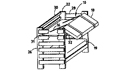
The reference numeral 10 (Figs. 1 and 2) generally designates a mattress
securing device embodying the present invention. In the illustrated example,
the
mattress securing device 10 includes a strap 12 configured to form a loop
section 14 and
leader portion 16 wherein the loop 14 is adapted to secure a bed mattress 18.
Mattress
securing device 10 further includes a buckle 20 slidably engaged with strap 12
and
adapted to adjust the size of loop 14 formed by strap 12. Leader portion 16 of
strap 12
is adapted to be attached to a bed frame 22 whereby mattress 18 may be
partially
removed from bed frame 22 thereby allowing easy access to mattress 18 for
purpose of
changing bed linens (not shown) and the like.
The illustrated straps 12 are constructed of nylon, or a material similar to
that
used in the manufacturing of automobile seatbelts, however, materials
displaying similar
properties and characteristics may be employed. It is preferable that at least
two straps
12 are used to secure mattress 18 and that straps 12 be equally spaced along
the length of
mattress 18. However, any number of straps 12 may be employed including, a
single
strap if properly centered along the length of mattress 18.
Strap 12 is slidably engaged with buckle 20 such that strap 12 forms loop
section
14 and leader portion 16. The illustrated buckle (Figs. 5 and 6) is adapted
such that the
size of loop 14 may be adjusted thereby allowing the operator to snuggly fit
strap 12
about mattress 18.
Bed frame 22 includes a plurality of legs 26, a plurality of bed rails 28, a
plurality of back rail 30, a plurality of front rails 32 and mattress supports
31. Front
rails 32 are preferably removable thereby allowing easy access to the
associated mattress
18. Bed frame 22 is adapted to support upper mattress 18 and a lower mattress
19 (Fig.
7).
-3-

CA 02321575 2000-08-28
WO 99/44476 PCTNS99/04835
Several adaptations and configurations of the mattress-securing device 10 are
possible. In one particular embodiment of the present invention, leader
portion 16 of
strap 12 is provided with a mounting bracket 24 (Figs. 3 and 4) that is
adapted to mount
to bed frame 22. Mounting bracket 24 {Fig. 9) is provided with an aperture 34
located
therein and adapted to receive a plurality of mechanical fasteners 36 there
through such
as wood screws, lags, nuts and bolts, and the like. Mounting bracket 24 is
attached to
mattress support 31 (Figs. 2 and 3), however, mounting bracket 24 may be
secured to
any suitable component of bed frame 22.
In another embodiment of the present invention, leader portion 16 (Fig. 7) of
strap 12 is provided with a first securing section 38, a second securing
section 40, and a
quick connector 42 located therebetween and operably connecting first securing
section
38 to second securing section 40. First securing section 38 may be adapted to
attach
directly to a component of bed frame 22, or may be provided with bracket 24
(Figs. 3
and 4). Quick connector 42 (Fig. 8) is provided a female portion 44 and a male
portion
46 adapted to be matably received within female portion 44 such that male
portion 46
may be easily released from connection with female portion 44 thereby allowing
the
complete removal of mattress 18 from bed frame 22. Male portion 46 (Fig. 9) of
quick
connector 42 is adapted such that the operable length of second securing
section 40 of
leader portion 16 may be adjusted thereby allowing the operator to adjust the
distance
mattress 18 may be removed from bed frame 22.
In yet another embodiment of the present invention first securing section 38
(Fig.
10) of leader portion 16 is attached to back rail 30 of bed frame 22 by way of
a first
mounting bracket 48 adapted to attach to rear rail 48 as described in further
detail
below. First securing section 38 of leader portion 16 extends beyond mounting
bracket
48 and extends beneath mattress 18 and mattress support 31 to front rail 32
where first
securing section 38 of leader portion 16 is connected to front rail 32 by way
of a second
mounting bracket 50 (Fig. 11). First mounting bracket 48 and second mounting
bracket
50 are each provided with a plurality of mounting apertures 52 adapted to
receive
mechanical fasteners 54 therein, such as wood screws, lags, nuts and bolts,
and the like.
By extending first securing section 38 of leader portion 16 below mattress 18
and
mattress support 31 and attaching first securing section to rear rail 30 and
to front rail 32
by way of mounting plate 48 and mounting plate 50, respectively, mattress 18
and

CA 02321575 2000-08-28
WO 99/44476 PCT/US99/04835
mattress support 31 are prevented from falling downward onto a lower bunk if
mattress
support 31 and/or mattress 18 are shifted within bed frame 22.
In still yet another embodiment of the present invention, first securing
section 38
(Figs. 7 and 12) is provided with a pair of grommets 56 located therein and
adapted to
receive mechanical fasteners 58 such as wood screws or bolts therein. The
grommets 56
are located within first securing section 38 of leader portion 16 such that
mechanical
fasteners 58 are mounted within mattress support 31 approximately 1/3 of the
distance
between rear rail 30 and front rail 32. Fastening first securing section 38 of
leader
portion 16 to mattress support 31 acts to reduce the moment arm of mattress 18
acting
upon bed frame 22 by way of leader portion 16 thereby decreasing the chance of
having
the weight of the mattress 18 tip bed frame 22 forward when mattress 18 is
partially
removed from within bed frame 22 during the linen changing process.
Loop 14 (Figs. 12-15) is adapted to mattress 18 in at least two
configurations. In
the first configuration (Figs. 12 and 13) loop 14 of strap 12 is positioned
about the
circumference of the mattress, thereby making mattress-securing device 10
adaptable to
any mattress. In an alternate configuration, loop 14 (Figs. 14 and 15) is
threaded
through handles 60 of mattress 18 thereby eliminating the need for the loop 14
to pass
above mattress 18. It should be noted that the alternative configuration of
loop 14
should only be employed with mattress 18 having handles 60 sufficiently
secured to
mattress 18.
The mattress securing device 10 as described above provides an uncomplicated,
easy to assemble apparatus for securing a mattress 18 to a bed frame 22
wherein the
mattress 18 is partially removable from the bed frame 22 thereby allowing easy
access to
mattress 18 for the purpose of changing bed linens and the like. In addition,
the
mattress-securing device 10 allows a single person to adjust mattress 18 and
change the
linens associated with the upper mattress 18 without aid of a second person.
In the foregoing description, it will be readily appreciated by those skilled
in the
art that modifications may be made to the invention without departing from the
concepts
disclosed herein. Such modifications are to be considered as included in the
following
claims, unless these claims by their language expressly state otherwise.
-5-

Dessin représentatif
Une figure unique qui représente un dessin illustrant l'invention.
États administratifs

2024-08-01 : Dans le cadre de la transition vers les Brevets de nouvelle génération (BNG), la base de données sur les brevets canadiens (BDBC) contient désormais un Historique d'événement plus détaillé, qui reproduit le Journal des événements de notre nouvelle solution interne.

Veuillez noter que les événements débutant par « Inactive : » se réfèrent à des événements qui ne sont plus utilisés dans notre nouvelle solution interne.

Pour une meilleure compréhension de l'état de la demande ou brevet qui figure sur cette page, la rubrique Mise en garde , et les descriptions de Brevet , Historique d'événement , Taxes périodiques et Historique des paiements devraient être consultées.

Historique d'événement

Description Date
Demande non rétablie avant l'échéance 2003-03-04
Le délai pour l'annulation est expiré 2003-03-04
Réputée abandonnée - omission de répondre à un avis sur les taxes pour le maintien en état 2002-03-04
Inactive : Page couverture publiée 2000-11-29
Inactive : CIB en 1re position 2000-11-23
Inactive : Notice - Entrée phase nat. - Pas de RE 2000-11-10
Demande reçue - PCT 2000-11-03
Demande publiée (accessible au public) 1999-09-10

Historique d'abandonnement

Date d'abandonnement Raison Date de rétablissement
2002-03-04

Taxes périodiques

Le dernier paiement a été reçu le 2001-01-08

Avis : Si le paiement en totalité n'a pas été reçu au plus tard à la date indiquée, une taxe supplémentaire peut être imposée, soit une des taxes suivantes :

  • taxe de rétablissement ;
  • taxe pour paiement en souffrance ; ou
  • taxe additionnelle pour le renversement d'une péremption réputée.

Les taxes sur les brevets sont ajustées au 1er janvier de chaque année. Les montants ci-dessus sont les montants actuels s'ils sont reçus au plus tard le 31 décembre de l'année en cours.
Veuillez vous référer à la page web des taxes sur les brevets de l'OPIC pour voir tous les montants actuels des taxes.

Historique des taxes

Type de taxes Anniversaire Échéance Date payée
Taxe nationale de base - petite 2000-08-28
TM (demande, 2e anniv.) - petite 02 2001-03-05 2001-01-08
Titulaires au dossier

Les titulaires actuels et antérieures au dossier sont affichés en ordre alphabétique.

Titulaires actuels au dossier
MARK R. PERKINS
BRANDON J. WINKEL
Titulaires antérieures au dossier
S.O.
Les propriétaires antérieurs qui ne figurent pas dans la liste des « Propriétaires au dossier » apparaîtront dans d'autres documents au dossier.
Documents

Pour visionner les fichiers sélectionnés, entrer le code reCAPTCHA :


Pour visualiser une image, cliquer sur un lien dans la colonne description du document. Pour télécharger l'image (les images), cliquer l'une ou plusieurs cases à cocher dans la première colonne et ensuite cliquer sur le bouton "Télécharger sélection en format PDF (archive Zip)" ou le bouton "Télécharger sélection (en un fichier PDF fusionné)".

Liste des documents de brevet publiés et non publiés sur la BDBC .

Si vous avez des difficultés à accéder au contenu, veuillez communiquer avec le Centre de services à la clientèle au 1-866-997-1936, ou envoyer un courriel au Centre de service à la clientèle de l'OPIC.


Description du
Document 
Date
(aaaa-mm-jj) 
Nombre de pages   Taille de l'image (Ko) 
Dessin représentatif 2000-11-28 1 9
Revendications 2000-08-28 8 328
Revendications 2000-08-27 7 305
Description 2000-08-27 5 298
Abrégé 2000-08-27 1 50
Dessins 2000-08-27 3 84
Rappel de taxe de maintien due 2000-11-07 1 112
Avis d'entree dans la phase nationale 2000-11-09 1 195
Courtoisie - Lettre d'abandon (taxe de maintien en état) 2002-04-01 1 182
PCT 2000-08-27 3 137
PCT 2000-08-28 5 218