Sélection de la langue

Search

Sommaire du brevet 2322546 

Énoncé de désistement de responsabilité concernant l'information provenant de tiers

Une partie des informations de ce site Web a été fournie par des sources externes. Le gouvernement du Canada n'assume aucune responsabilité concernant la précision, l'actualité ou la fiabilité des informations fournies par les sources externes. Les utilisateurs qui désirent employer cette information devraient consulter directement la source des informations. Le contenu fourni par les sources externes n'est pas assujetti aux exigences sur les langues officielles, la protection des renseignements personnels et l'accessibilité.

Disponibilité de l'Abrégé et des Revendications

L'apparition de différences dans le texte et l'image des Revendications et de l'Abrégé dépend du moment auquel le document est publié. Les textes des Revendications et de l'Abrégé sont affichés :

  • lorsque la demande peut être examinée par le public;
  • lorsque le brevet est émis (délivrance).
(12) Demande de brevet: (11) CA 2322546
(54) Titre français: PROCEDE ET DISPOSITIF POUR LA FABRICATION DE TUBES
(54) Titre anglais: METHOD AND DEVICE FOR PRODUCING PIPES
Statut: Réputée abandonnée et au-delà du délai pour le rétablissement - en attente de la réponse à l’avis de communication rejetée
Données bibliographiques
(51) Classification internationale des brevets (CIB):
  • B21C 37/08 (2006.01)
(72) Inventeurs :
  • GYSI, PETER (Suisse)
(73) Titulaires :
  • ELPATRONIC AG
(71) Demandeurs :
  • ELPATRONIC AG (Suisse)
(74) Agent: ROBIC AGENCE PI S.E.C./ROBIC IP AGENCY LP
(74) Co-agent:
(45) Délivré:
(86) Date de dépôt PCT: 1999-02-17
(87) Mise à la disponibilité du public: 1999-09-10
Licence disponible: S.O.
Cédé au domaine public: S.O.
(25) Langue des documents déposés: Anglais

Traité de coopération en matière de brevets (PCT): Oui
(86) Numéro de la demande PCT: PCT/CH1999/000078
(87) Numéro de publication internationale PCT: CH1999000078
(85) Entrée nationale: 2000-08-30

(30) Données de priorité de la demande:
Numéro de la demande Pays / territoire Date
2397/98 (Suisse) 1998-12-02
513/98 (Suisse) 1998-03-04

Abrégés

Abrégé français

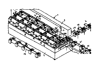
Plusieurs tubes à souder, ou déjà soudés (7, 8, 9) sont positionnés sur une table (2). Un dispositif de soudage au laser (3, 4, 5, 6) soude les joints de tubes respectifs. Pendant qu'un tube est soudé, il est possible de charger les autres positions de la table avec les tubes encore à souder, et de décharger les tubes déjà soudés. Ceci permet une utilisation optimale du dispositif de soudage au laser.


Abrégé anglais


Several pipes (7, 8, 9) which are to be welded or have already been welded are
arranged on a table (2). A laser welding device (3, 4, 5, 6) welds the
relevant pipe joints. While one pipe is welded it is possible to load the
other positions on the table with pipes still to be welded and to unload pipes
which have already been welded. This allows for optimal utilisation of the
laser welding device.

Revendications

Note : Les revendications sont présentées dans la langue officielle dans laquelle elles ont été soumises.


4
Claims
1. Apparatus (1) for welding the longitudinal seam of tubes (7, 8, 9) by means
of a laser beam
(4), characterized in that a table (2) is provided which has holding means
arranged for
parallel holding of at least two tubes, and a laser beam source whose laser
beam emission
head (5), which is arranged above the table, is traversable in the
longitudinal direction of the
table and is traversable in the transverse direction by traversing of either
the emission head
(5) or the table (2), wherein the holding means have clamping jaws that can be
shifted into
position towards and away from one another, and a device is provided for
detecting the
position of the welding edges of tubes over the length of the tube.
2. Apparatus according to Claim 1, characterized in that the holding means are
provided with
exchangeable shaped pieces which have a shape matching a predetermined tube
outer profile.
3. Method for the operation of an apparatus for welding the longitudinal seam
of tubes (7, 8,
9) by means of a laser beam (4), in which apparatus a table (2) is provided
which has holding
means arranged for parallel holding of at least two tubes, and a laser beam
source whose
laser beam emission head (5), which is arranged above the table, is
traversable in the
longitudinal direction of the table and is traversable in the transverse
direction by traversing
of either the emission head (5) or the table (2), wherein the holding means
have clamping
jaws that can be shifted into position towards and away from one another, and
a device is
provided for detecting the position of the welding edges of tubes over the
length of the tube,
characterized in that a loading apparatus loads a tube to be welded into the
parted clamping
jaws and positions the tube in the clamping jaws by shifting it forward and
back, and if need
be rotating it, as directed by the device for detecting the position of the
edges, until the
correct welding position of the tube is obtained, and in that the clamping
jaws are then closed
and the tube is welded.
4. Method according to Claim 3, characterized in that while one tube is being
welded,
unloading of a tube that has already been welded is effected.
5. Method according to Claim 4, characterized in that while one tube is being
welded,
loading and positioning of another tube for welding are also effected.
6. Method according to Claim 3, characterized in that a tube for welding is
loaded and a
welded tube is simultaneously unloaded in a first step, [and] in that the tube
is welded in a
second step, after which the first step is repeated.

Description

Note : Les descriptions sont présentées dans la langue officielle dans laquelle elles ont été soumises.


CA 02322546 2000-08-30
1
METHOD AND DEVICE FOR PRODUCING PIPES
The invention relates to an apparatus according to the introductory part of
Claim 1, and a
method for the operation of such an apparatus.
It is known that bodies formed by bending sheet-metal blanks into tubular
shapes may be
welded by laser along their longitudinal seam, particularly with a butt joint,
so that welded
tubes are formed. These tubes, whose cross-section may be of any desired
shape, can be
formed, particularly by a subsequent hydroforming process, into shaped bodies
that can be
used in various fields, and particularly in motor vehicle body construction.
JP 02076648 A
shows an apparatus with two working zones for coiling and welding strips
around an object.
Coiling takes place in one zone, and welding in the other. JP 04118191 A shows
the welding
of various tube sections which are arranged and aligned coaxially one after
another for
welding. JP 09029477 A shows tube welding with a revolver-like rotatable
holder for several
tubes. WO-A 98/26898 shows the welding of flat parts that are fixed adjacent
to one another
on tables, by means of a single laser able to serve both tables.
It is an object of the invention to provide a more efficiently designed
apparatus for the
manufacture of tubes.
This object is realized by the characterizing features of Claims 1 and/or 3.
Embodiments of the invention given by way of example will now be described in
detail with
reference to the sole figure.
The figure shows a schematic perspective view of an apparatus 1 for the laser
welding of
tubes. The apparatus has a table 2 and a laser welding unit 3 arranged above
it. The laser
2 0 welding unit 3 has a laser source (not shown) from which the laser beam 4
is directed to its
emission head 5. The emission head 5 of the laser welding unit is arranged on
a carriage 6
which can be traversed back and forth in the directions of the arrow A to
carry out the
welding.
The table 2 has a number of holding positions for tubes 7, 8, 9. The tubes are
arranged
parallel on the table 2. Holding means are provided for securing the tubes on
the table. The
holding means for each tube may comprise a plurality of clamping jaws 10 and
11 each
provided with shaped pieces 12 and 13 adapted to the shape and diameter of the
individual
tube. Thus, shaped pieces 12' and 13' are provided for the tube 8, instead of
the shaped pieces
12 and 13 used for the tube 7. The invention offers - and the embodiment shows
- a highly
flexible machine concept that is also very well suited for small production
runs and also for
laboratory work. With this in mind, the clamps are designed and constructed so
that the
shaped pieces can be changed within a short time; and, as the example shows,
different
3 0 shaped pieces can be fitted at the same time. The clamping jaws 10, 11
(and the other
clamping jaws shown without reference numbers) can be shifted into position
towards and
away from one another to receive and hold the individual tube and release it
after welding.
Tubes are positioned on the table in the rounded and as yet unwelded condition
by a loading
apparatus (not shown). At this stage, the clamping jaws are still sufficiently
wide open for the

CA 02322546 2000-08-30
2
tube to be loaded and positioned as required by shifting it forward and back,
and if need be
by rotating it about its longitudinal axis. To obtain the best possible welded
joint, a device
operating at least semi-automatically or operating as a control or regulating
device is
preferably provided which detects the position of the welding edge over the
entire length of
the tube, preferably contactlessly by means of optical sensors, and modifies
the position of
the tube in the positioning/clamping operation. Once the tube to be welded is
in the welding
position, the clamping jaws with the shaped pieces mounted thereon are closed
sufficiently to
hold the tube in the correct position for welding. Contact by the shaped
pieces of the clamps
with the outer cylindrical surface of the tube is preferably only partial and
is preferably
non-metallic (i.e. the shaped pieces are made of plastic material), to avoid
damaging the
surface of the tube.
»0 '~'he operations of loading and receiving the tubes and securing them on
the table are
controlled by a control device, and in particular by computer. During welding,
the laser may
be made to follow the adjoining welding edges in a known manner by means of a
seam
tracking system 25. After welding, the clamping jaws are released again and
the tube is then
removed from the table by an unloading device (not shown in detail). This is
schematically
indicated in the drawing for the tube 7 by the arrow B pointing in the
unloading direction and
the tube 7' showing the tube in the unloaded position. The unloaded tube may
be cut into
various desired lengths e.g. by a cutting device 15 which is only shown
schematically in the
drawing.
This table with its plurality of mounting positions for tubes allows welding
to be performed
simultaneously with loading and unloading. Thus, in the illustrated example,
the tube 8 can
be welded while the tube 7 that has already been welded is being unloaded. At
the same time,
the as yet unwelded tube 9 can be loaded on to the table and secured with the
corresponding
clamping jaws. However, the loading, welding and unloading cycles may follow
one another
in succession, instead of being performed simultaneously, or they may be
performed in
combination, e.g. with simultaneous loading and unloading of, in each case,
one tube,
followed by welding of one tube; [either of] which will prevent the welding
from being
affected by shocks due to loading or unloading. The method and/or apparatus
make it
possible to obtain optimum utilization of the laser welding plant. Thus, in
the example
shown, after the laser has completed the welding of the tube 8, it can be made
to proceed
directly to the welding of the tube 9, e.g. by traversing the table 2 in a
direction indicated by
the arrow C to locate the laser head over the welding edges of the tube 9.
While the tube 9 is
being welded, the tube 8 that has already been welded can be unloaded, and
e.g. a fresh tube
can simultaneously be put on the table by the loading device to replace the
tube shown as
30 tube 7. After the tube 9 has been welded, the table can then be traversed
again so that the tube
which has taken the place of tube 7 can be welded, while the tube that has
already been
welded is unloaded. Unloading can be effected e.g. by table-mounted power-
driven rollers
16, which are shown for the tube 9 as an example. Of course, instead of moving
the table 2
transversely with respect to the welding direction, it is also possible to
provide a fixed table
and to traverse the welding unit accordingly. In this case i.e. if the table
is stationary, the
loading and unloading devices will need to be traversable also.
The method and/or apparatus make it possible e.g. to weld alternately a tube
with a smaller

CA 02322546 2000-08-30
3
diameter and a tube with a larger diameter. This can be done always at the
same table
position for each tube diameter, and unloading can also be organized
accordingly so that the
welded tubes are already sorted by diameter when they leave the shop or go
into interim
storage.
The illustrated arrangement and/or method with their capacity for several
tubes enable
utilization of the welding unit, and its adaptation to the bending unit, to be
optimized. The
bending unit for the tubes is essentially time-dependent on the diameter of
the tubes, not on
their length. The welding, on the other hand, is time-dependent on the length
of the welded
seam to be produced. The method and/or arrangement which have been described
allow
optimal coordination of these operations. Buffer storage or a transfer device
may be arranged
1~D upstream of the loading device for the table 2, to provide interim storage
for bent tubes.
Buffer storage or a transfer device may also be provided at the discharge end
of the table 2.
The figure moreover shows how the clamping jaws with shaped pieces can also be
used for
easy clamping of a tapered bent tube 17, which is shown schematically
alongside the table in
order to illustrate this possibility. It is possible to adapt flexibly to
different tube diameters or
even to tapered tubes, simply by replacing the shaped pieces 12, 13. It is
likewise possible to
adapt to tubes with a different cross-sectional profile by replacing the
shaped pieces. This is
also indicated schematically alongside the table in the figure, by means of
the tubes 18, 19
and 20 (only partly shown), which have a non-round profile and are held by
correspondingly
formed shaped pieces 12, 13.
For the quality of the laser welding, it is essential that the opposing edge
faces of the bent
20 sheet-metal blank should not be out of parallel with one another (i.e.
should not form a vee)
by more than a tolerable amount. This is especially important where the laser
welded tubes
are subjected to a further forming process, and in particular a hydroforming
process, in which
the weld seam can be subjected to a correspondingly high loading. Therefore
the edges of the
bent sheet-metal blanks are preferably acted on in the region of the laser
emission head 5 so
that the edge faces are essentially parallel with one another in the welding
zone. This is
indicated in the figure by the rolls or rollers 22 and 23, which impinge on
the edges to a
greater or lesser degree thus giving a parallel alignment of the edge faces so
that laser
welding can be conducted within the range of permissible tolerance. Instead of
the rolls
shown (preferably two in number), other means of impinging on the edges may be
provided.
The rolls may for example be set at an adjustable fixed height which
corresponds to the
preferred edge-orientation.
3;0 Instead of the arrangement shown with its three tube-receiving positions,
it is possible to
provide two receiving positions only, or more than three receiving positions.
It is also
possible to provide more than one laser welding unit. Any type of laser
source, e.g. C02 and
YAG lasers, can be adopted. In principle, it is possible to produce a lap-
welded seam instead
of the butt-welded seam that has been described. The tubes to be welded may be
formed e.g.
from sheet steel, chromium steel or aluminium. Possible sizes include in
particular tubes with
a diameter of 6 cm to 20 cm, a length of 50 cm to 3 m and a sheet-metal
thickness of 0.6 to 2
mm, although other dimensions are of course also possible.

Dessin représentatif
Une figure unique qui représente un dessin illustrant l'invention.
États administratifs

2024-08-01 : Dans le cadre de la transition vers les Brevets de nouvelle génération (BNG), la base de données sur les brevets canadiens (BDBC) contient désormais un Historique d'événement plus détaillé, qui reproduit le Journal des événements de notre nouvelle solution interne.

Veuillez noter que les événements débutant par « Inactive : » se réfèrent à des événements qui ne sont plus utilisés dans notre nouvelle solution interne.

Pour une meilleure compréhension de l'état de la demande ou brevet qui figure sur cette page, la rubrique Mise en garde , et les descriptions de Brevet , Historique d'événement , Taxes périodiques et Historique des paiements devraient être consultées.

Historique d'événement

Description Date
Inactive : CIB expirée 2014-01-01
Inactive : CIB de MCD 2006-03-12
Réputée abandonnée - omission de répondre à un avis sur les taxes pour le maintien en état 2005-02-17
Demande non rétablie avant l'échéance 2005-02-17
Inactive : Morte - RE jamais faite 2005-02-17
Inactive : Abandon.-RE+surtaxe impayées-Corr envoyée 2004-02-17
Lettre envoyée 2001-03-13
Inactive : Transfert individuel 2001-02-14
Inactive : Page couverture publiée 2000-12-01
Inactive : CIB en 1re position 2000-11-26
Inactive : Lettre de courtoisie - Preuve 2000-11-21
Inactive : Notice - Entrée phase nat. - Pas de RE 2000-11-15
Demande reçue - PCT 2000-11-10
Demande publiée (accessible au public) 1999-09-10

Historique d'abandonnement

Date d'abandonnement Raison Date de rétablissement
2005-02-17

Taxes périodiques

Le dernier paiement a été reçu le 2004-01-19

Avis : Si le paiement en totalité n'a pas été reçu au plus tard à la date indiquée, une taxe supplémentaire peut être imposée, soit une des taxes suivantes :

  • taxe de rétablissement ;
  • taxe pour paiement en souffrance ; ou
  • taxe additionnelle pour le renversement d'une péremption réputée.

Les taxes sur les brevets sont ajustées au 1er janvier de chaque année. Les montants ci-dessus sont les montants actuels s'ils sont reçus au plus tard le 31 décembre de l'année en cours.
Veuillez vous référer à la page web des taxes sur les brevets de l'OPIC pour voir tous les montants actuels des taxes.

Historique des taxes

Type de taxes Anniversaire Échéance Date payée
Taxe nationale de base - générale 2000-08-30
TM (demande, 2e anniv.) - générale 02 2001-02-19 2001-01-24
Enregistrement d'un document 2001-02-14
TM (demande, 3e anniv.) - générale 03 2002-02-18 2002-02-07
TM (demande, 4e anniv.) - générale 04 2003-02-17 2003-01-24
TM (demande, 5e anniv.) - générale 05 2004-02-17 2004-01-19
Titulaires au dossier

Les titulaires actuels et antérieures au dossier sont affichés en ordre alphabétique.

Titulaires actuels au dossier
ELPATRONIC AG
Titulaires antérieures au dossier
PETER GYSI
Les propriétaires antérieurs qui ne figurent pas dans la liste des « Propriétaires au dossier » apparaîtront dans d'autres documents au dossier.
Documents

Pour visionner les fichiers sélectionnés, entrer le code reCAPTCHA :


Pour visualiser une image, cliquer sur un lien dans la colonne description du document. Pour télécharger l'image (les images), cliquer l'une ou plusieurs cases à cocher dans la première colonne et ensuite cliquer sur le bouton "Télécharger sélection en format PDF (archive Zip)" ou le bouton "Télécharger sélection (en un fichier PDF fusionné)".

Liste des documents de brevet publiés et non publiés sur la BDBC .

Si vous avez des difficultés à accéder au contenu, veuillez communiquer avec le Centre de services à la clientèle au 1-866-997-1936, ou envoyer un courriel au Centre de service à la clientèle de l'OPIC.


Description du
Document 
Date
(aaaa-mm-jj) 
Nombre de pages   Taille de l'image (Ko) 
Dessin représentatif 2000-11-30 1 17
Description 2000-08-29 3 245
Abrégé 2000-08-29 1 63
Dessins 2000-08-29 1 40
Revendications 2000-08-29 1 60
Rappel de taxe de maintien due 2000-11-13 1 112
Avis d'entree dans la phase nationale 2000-11-14 1 195
Courtoisie - Certificat d'enregistrement (document(s) connexe(s)) 2001-03-12 1 113
Rappel - requête d'examen 2003-10-19 1 112
Courtoisie - Lettre d'abandon (requête d'examen) 2004-04-26 1 167
Courtoisie - Lettre d'abandon (taxe de maintien en état) 2005-04-13 1 174
Correspondance 2000-11-13 1 14
PCT 2000-08-29 12 401
Taxes 2003-01-23 1 30
Taxes 2002-02-06 1 30
Taxes 2001-01-23 1 31
Taxes 2004-01-18 1 28