Sélection de la langue

Search

Sommaire du brevet 2323321 

Énoncé de désistement de responsabilité concernant l'information provenant de tiers

Une partie des informations de ce site Web a été fournie par des sources externes. Le gouvernement du Canada n'assume aucune responsabilité concernant la précision, l'actualité ou la fiabilité des informations fournies par les sources externes. Les utilisateurs qui désirent employer cette information devraient consulter directement la source des informations. Le contenu fourni par les sources externes n'est pas assujetti aux exigences sur les langues officielles, la protection des renseignements personnels et l'accessibilité.

Disponibilité de l'Abrégé et des Revendications

L'apparition de différences dans le texte et l'image des Revendications et de l'Abrégé dépend du moment auquel le document est publié. Les textes des Revendications et de l'Abrégé sont affichés :

  • lorsque la demande peut être examinée par le public;
  • lorsque le brevet est émis (délivrance).
(12) Demande de brevet: (11) CA 2323321
(54) Titre français: DRESSEUR A MEULES
(54) Titre anglais: DRESSING APPARATUS FOR GRINDING WHEELS
Statut: Réputée abandonnée et au-delà du délai pour le rétablissement - en attente de la réponse à l’avis de communication rejetée
Données bibliographiques
Abrégés

Abrégé anglais


Dressing apparatus is provided for an ice skate grinding apparatus of the type
including a grinding wheel, a worktable for supporting a skate-holding jig for
movement over the table along a path determined by templates mounted on or in
the table, the grinding wheel being mounted for rotation about a centre spaced
a
predetermined distance above the table; the dressing apparatus having a body
with a base with a table engaging lower surface, and releasable means
associated with the body for drawing the base member against the table, a
horizontal traversing mechanism mounted on the body and at least one tool
holder pivotally mounted on the traversing mechanism and supporting a dressing
tool for arcuate movement transverse to a plane of rotation of the grinding
wheel.
The dressing apparatus is, preferably, for use with apparatus having a
conventional steel table, and the releasable means is a magnet supported in
the
body by a lever mechanism for movement between a table-engaging position
and a position sufficiently above the table to release the body for movement
over
the table. The tool holder is mounted on the traversing mechanism for rotation
about an axis which is preferably horizontal, and a second tool holder may be
provided movable in an arc having a vertical axis.

Revendications

Note : Les revendications sont présentées dans la langue officielle dans laquelle elles ont été soumises.


CLAIMS:
1. Dressing apparatus, for an ice skate grinding apparatus of the type
including a grinding wheel, a worktable for supporting a skate-holding jig for
movement over the table along a path determined by templates mounted on or in
the table, the grinding wheel being mounted for rotation about a centre spaced
a
predetermined distance above the table; the dressing apparatus comprising a
body having a base with a table engaging lower surface, and releasable means
associated with the body for drawing the base member against the table, a
horizontal traversing mechanism mounted on the body and at least one tool
holder pivotally mounted on the traversing mechanism and supporting a dressing
tool for arcuate movement transverse to a plane of rotation of the grinding
wheel.
2. Dressing apparatus according to Claim 1, for use with apparatus having a
conventional steel table, and the releasable means is a magnet supported in
the
body by a lever mechanism for movement between a table-engaging position
and a position sufficiently above the table to release the body for movement
over
the table.
3. Dressing apparatus according to Claim 1, wherein the tool holder is
mounted on the traversing mechanism for rotation about a horizontal axis.
4. Dressing apparatus according to Claim 3, wherein a second tool holder is
mounted on the traversing mechanism for movement in a horizontal arc.
5. Dressing apparatus according to Claim 3, wherein the tool is mounted on
an end of a sleeve axially adjustable relative to the tool holder such that a
cutting surface of the tool can be moved in an arc of preset radius about the
horizontal axis.
7

6. Dressing apparatus according to Claim 5, wherein the tool holder
provides an alternated mounting for the tool such that the cutting surface of
the
tool moves in an arc of much greater radius than said present radius.
7. Dressing apparatus according to Claim 3, wherein the tool holder is
mounted on said horizontal axis by a pivot pin, and a height gauge for
grinding
wheel is on one end of the pivot pin.
8. Dressing apparatus according to Claim 4, wherein the second tool holder
includes means to mount a dressing tool.
9. Dressing apparatus for grinding apparatus including a grinding wheel,
and a work table for supporting an article to be ground for application to the
grinding wheel, the grinding wheel being mounted for rotation about a centre
spaced a predetermined distance above the table; the dressing apparatus
comprising a body having a base with a table engaging lower surface, and
releasable means associated with the body for drawing the base member
magnetically against the table, a horizontal traversing mechanism mounted on
the body and at least one tool holder pivotally mounted on the traversing
mechanism and supporting a dressing tool for arcuate movement transverse to a
plane of rotation of the grinding wheel.
8

Description

Note : Les descriptions sont présentées dans la langue officielle dans laquelle elles ont été soumises.

CA 02323321 2000-10-17
DRESSING APPARATUS FOR GRINDING WHEELS
FIELD OF THE INVENTION
This invention relates to dressing apparatus for grinding wheels, more
particularly grinding wheels utilized in ice skate sharpening machines.
Skate sharpening machines typically provide a jig in which a skate to be
sharpened is mounted, and means to traverse the jig along a predetermined
path relative to a grinding wheel. Skate blades are usually hollow ground,
which
requires that the outer perimeter of a grinding wheel rotating in a common
plane
with the blade is dressed to an appropriate convex profile at an appropriate
elevation relative to the blade to be sharpened, although in some cases a flat
grind is desired, and provision may be desirable for cross-grinding where
recontouring of the blade is required. It has however proved difficult to
provide
satisfactory arrangements for providing suitable dressing facilities for the
grinding wheels used without either increasing the complexity and reducing the
flexibility of the machine, or using add-in devices which are difficult to
align.
U.S. Patent No. 5,897,428 (Sakcriska) describes a dressing apparatus for
use with a skate sharpening machine, in which the dressing tool is held by a
dressing arm pivotable between stored and operative position relative to a
housing surrounding the grinding wheel and associated with a relative
elaborate
mechanism for positioning the dressing tool relative to the grinding wheel.
U.S. Patent No. 4,520,788 (Melvin) describes a dresser for precision
grinding wheels in which a dressing tool with a flat end is rotatable in a
housing.
The housing is magnetically secured to a magnetic table and the table and
grinding wheel are adjusted up and down relative to one another.
U.S. No. 4,502,457 (Marron) describes a universal multiple angle
workpiece holder with provision for attachment of a dressing tool.
U.S. Patent No. 5,441,449 (Hart) describes a grinding wheel dresser

CA 02323321 2000-10-17
"integratable" with grinding apparatus. The dresser includes a housing
surrounding the grinding wheel and support means for positioning the dressing
tool, somewhat similar to the Sakcriska apparatus discussed above.
U.S. Patent No. 5,591,069 (Wurthmann) discloses a skate sharpener
having a built-in dressing tool. It includes means for positioning the tool
and
moving it to an inactive position, built into the tool.
A very widely used type of ice skate sharpening machine has a table
mounting a grinding wheel for rotation about a vertical axis, and a flat steel
worktable on or into which various jigs and templates may be located. A
permanently-installed dressing apparatus, or one which involves substantial
installation, is an obstruction or inconvenience to be avoided, if possible.
In a
high volume skate grinding facility, more than one sharpening machine may be
provided, together with a cross-grinding machine for contouring and rough-
grinding, and it would be desirable to provide a dressing apparatus which
could
be used with all such machines.
According to the invention, there is provided dressing apparatus, for a
skate grinding apparatus of the type including a grinding wheel, a worktable
for
supporting a skate-holding jig for movement over the table along a path
determined by templates mounted on or in the table, the grinding wheel being
mounted for rotation about a centre spaced a predetermined distance above the
table; the dressing apparatus comprising a body having a base with a table
engaging lower surface, and releasable means associated with the body for
drawing the base member against the table, a horizontal traversing mechanism
mounted on the body and at least one tool holder pivotally mounted on the
traversing mechanism and supporting a dressing tool for arcuate movement
transverse to a plane of rotation of the grinding wheel. The dressing
apparatus
is, preferably, for use with apparatus having a conventional steel table, and
the
releasable means is a magnet supported in the body by a lever mechanism for
movement between a table-engaging position and a position sufficiently above
2

CA 02323321 2000-10-17
the table to release the body for movement over the table. The tool holder is
mounted on the traversing mechanism for rotation about an axis which is
preferably horizontal, and a second tool holder may be provided movable in an
arc having a vertical axis.
Further features of the invention will be apparent from the following
description with reference to the accompanying drawings.
SHORT DESCRIPTION OF THE DRAWINGS
Figure 1 is a plan view of the dressing apparatus of the invention.
Figure 2 is a side elevation view thereof.
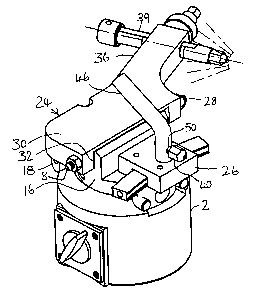
Figure 3 is a perspective view thereof.
Figure 4 is another side elevation view thereof.
DETAILED DESCRIPTION
The dressing apparatus comprises a body 2 having a base ground flat for
frictional contact with a flat steel table 4 of a skate grinding machine,
whether a
sharpening machine with a grinding wheel rotating in a plane which is
horizontal
and parallel to the table, or a contouring and rough-grinding machine with a
grinding wheel rotating in a vertical plane about an axis which is horizontal
for
cross-grinding. A skate blade to be ground is held horizontally in a jig. Both
types of wheel may, in some cases, be mounted on the same table. For reasons
that will become apparent, the height of the grinding wheel (the centre plane
of
horizontal wheels, and the rotational axis of vertical wheels) should be
adjusted
to the same predetermined level for every machine with which the dressing
3

CA 02323321 2000-10-17
apparatus is to be used, although the height of a vertical wheel is not very
critical.
The body 2 has a straight horizontal keyway 10 machined in its upper
surface which is engaged by parallel rails 12 supported on the body 16 of a
traversing mechanism. A drive screw (not seen) with a handle or hand wheel 18
at one end is journalled at its ends 14 in the body 16, with the screw
engaging a
threaded lug (not shown) extending upwardly from the body 2 into the keyway.
The tool holder can be traversed horizontally and incrementally relative to
the
base by turning the hand wheel 18. Mounted on the body 16 of the traversing
mechanism are two tool holders 24 and 26.
The first tool holder 24 has a body 30 rotatable about a pivot pin 28 which
extends horizontally through the body 16 of the traversing mechanism and
through lugs 32 on the body 30 of the tool holder. Formed on one end of the
pin
28 is a projection 8 which can act as a gauge for checking the height of the
periphery of a horizontal grinding wheel. An actuating lever (not shown) may
be
provided on the body 30 to assist in pivoting the body about the pivot pin 28.
A
tool holder arm 36 extends from the body at an angle from the axis of the
pivot
pin 28 and is provided with intersecting bores co-axial with longitudinal axis
of
the arm and transverse to that longitudinal axis. A set screw 38 in the co-
axial
bore, which is threaded, secures the shank of a sleeve 39 into which is
screwed
a tool 40 having a diamond dressing surface 42 at its outer end, the distance
of
the surface 42 from the axis of the pivot pin 28 being adjustable by releasing
the
set screw 28 and moving the sleeve 39 axially. The sleeve may be graduated to
facilitate setting the distance between the tool surtace and the axis, Which
ultimately determines the radius of a hollow grind applied to a skate. This
distance may be adjustable, for example, between 3/e inch and 1'/2 inches. The
tool may also be removed from the sleeve and screwed into a bore in the set
screw 38. With this arrangement, the distance of the tool surtace from the
axis
of the pivot 28 is sufficient that radius of a grind applied to a skate blade
by a
4

CA 02323321 2000-10-17
grinding stone so radiused is essentially flat. Although the drawings show
separate tools in each of the three possible locations to be described, for
reasons of economy, it may be preferred to move a single tool from one
location
to another, since only one may be used at a time.
The body 22 also carries horizontal arcuate track 43, along which the
second tool holder 26 may be moved in a horizontal plane by means of a handle
46 to move a tool 40 having its shank screwed into a socket 50 such that the
dressing surface 42 can dress a grinding wheel rotating in a vertical plane on
a
horizontal axis.
As shown, no vertical adjustment is provided for the centre height at
which the dressing tools will contact grinding wheels to be dressed. This
height
may be, for example, 4'/ inches (slightly higher for a tool in socket 50). All
grinding wheels to be dressed by the device should be set at this same height
above their associated tables. It would, of course, be possible to provide for
vertical adjustment of the tool holders to accommodate different grinding
wheel
heights, but this requires the height to be adjusted or checked for each
dressing
operation, delaying operation, reducing precision and increasing the
possibility
of error.
In order to secure the base to the table 4, a cavity within the body 2
accommodates a powerful magnet 50 with a flat under-surface, which is
suspended from a cam 52 on a lever 54 so that it may be lowered onto or raised
from the table 4 to lock or unlock the base from the table. Other securing
means
such as suction cups could possibly be used, but a magnet is believed most
satisfactory and durable.
In use, the tool 40 is located, if necessary, in the location appropriate to
the type of dressing to be performed on a grinding wheel to be dressed, the
sleeve 39 is adjusted, if applicable, to provide a desired radius of hollow
grind,
and the dressing apparatus is placed on the table so that the surface 42 of
the
tool is almost touching the periphery of the wheel to be dressed. The body 2
is
5

CA 02323321 2000-10-17
then locked to the table by engaging the magnet 50 with the table 4. The
grinding wheel is placed in rotation, and the tool 40 is fed into the grinding
wheel
by using the wheel 18 to move the body 16, while rocking the applicable tool
holder about the pin 28 or along the track 43.
It will, of course, be understood that the apparatus described is exemplary
only, and its construction and details may be varied within the scope of the
appended claims.
6

Dessin représentatif
Une figure unique qui représente un dessin illustrant l'invention.
États administratifs

2024-08-01 : Dans le cadre de la transition vers les Brevets de nouvelle génération (BNG), la base de données sur les brevets canadiens (BDBC) contient désormais un Historique d'événement plus détaillé, qui reproduit le Journal des événements de notre nouvelle solution interne.

Veuillez noter que les événements débutant par « Inactive : » se réfèrent à des événements qui ne sont plus utilisés dans notre nouvelle solution interne.

Pour une meilleure compréhension de l'état de la demande ou brevet qui figure sur cette page, la rubrique Mise en garde , et les descriptions de Brevet , Historique d'événement , Taxes périodiques et Historique des paiements devraient être consultées.

Historique d'événement

Description Date
Inactive : CIB désactivée 2012-01-07
Inactive : CIB attribuée 2012-01-01
Inactive : CIB expirée 2012-01-01
Inactive : CIB de MCD 2006-03-12
Le délai pour l'annulation est expiré 2004-10-18
Demande non rétablie avant l'échéance 2004-10-18
Réputée abandonnée - omission de répondre à un avis sur les taxes pour le maintien en état 2003-10-17
Inactive : Page couverture publiée 2002-04-19
Demande publiée (accessible au public) 2002-04-17
Lettre envoyée 2001-06-07
Inactive : Transfert individuel 2001-05-11
Inactive : CIB en 1re position 2000-12-28
Inactive : Lettre de courtoisie - Preuve 2000-11-28
Inactive : Certificat de dépôt - Sans RE (Anglais) 2000-11-23
Exigences de dépôt - jugé conforme 2000-11-23
Demande reçue - nationale ordinaire 2000-11-22

Historique d'abandonnement

Date d'abandonnement Raison Date de rétablissement
2003-10-17

Taxes périodiques

Le dernier paiement a été reçu le 2002-08-07

Avis : Si le paiement en totalité n'a pas été reçu au plus tard à la date indiquée, une taxe supplémentaire peut être imposée, soit une des taxes suivantes :

  • taxe de rétablissement ;
  • taxe pour paiement en souffrance ; ou
  • taxe additionnelle pour le renversement d'une péremption réputée.

Veuillez vous référer à la page web des taxes sur les brevets de l'OPIC pour voir tous les montants actuels des taxes.

Historique des taxes

Type de taxes Anniversaire Échéance Date payée
Taxe pour le dépôt - générale 2000-10-17
Enregistrement d'un document 2001-05-11
TM (demande, 2e anniv.) - générale 02 2002-10-17 2002-08-07
Titulaires au dossier

Les titulaires actuels et antérieures au dossier sont affichés en ordre alphabétique.

Titulaires actuels au dossier
GUSPRO INC.
Titulaires antérieures au dossier
AUGUST SUNNEN
Les propriétaires antérieurs qui ne figurent pas dans la liste des « Propriétaires au dossier » apparaîtront dans d'autres documents au dossier.
Documents

Pour visionner les fichiers sélectionnés, entrer le code reCAPTCHA :


Pour visualiser une image, cliquer sur un lien dans la colonne description du document. Pour télécharger l'image (les images), cliquer l'une ou plusieurs cases à cocher dans la première colonne et ensuite cliquer sur le bouton "Télécharger sélection en format PDF (archive Zip)" ou le bouton "Télécharger sélection (en un fichier PDF fusionné)".

Liste des documents de brevet publiés et non publiés sur la BDBC .

Si vous avez des difficultés à accéder au contenu, veuillez communiquer avec le Centre de services à la clientèle au 1-866-997-1936, ou envoyer un courriel au Centre de service à la clientèle de l'OPIC.


Description du
Document 
Date
(aaaa-mm-jj) 
Nombre de pages   Taille de l'image (Ko) 
Dessin représentatif 2002-03-20 1 11
Abrégé 2000-10-17 1 35
Description 2000-10-17 6 266
Revendications 2000-10-17 2 80
Dessins 2000-10-17 2 45
Page couverture 2002-04-19 1 47
Certificat de dépôt (anglais) 2000-11-23 1 164
Courtoisie - Certificat d'enregistrement (document(s) connexe(s)) 2001-06-07 1 112
Rappel de taxe de maintien due 2002-06-18 1 114
Courtoisie - Lettre d'abandon (taxe de maintien en état) 2003-12-15 1 177
Correspondance 2000-11-23 1 14
Taxes 2002-08-07 1 31