Note : Les descriptions sont présentées dans la langue officielle dans laquelle elles ont été soumises.
CA 02324172 2000-10-23
Fill Level Detector
This invention relates to a fill-level detector employing the radar principle
for
gaging the level of the lower of two substances layered one atop the other
within a
container, said detector incorporating a first electrical conductor and a
second electrical
conductor, both extending parallel to each other in an essentially straight
direction and
protruding into the lower substance; a generator positioned outside the lower
and the
upper substance at the end of the first electrical conductor and,
respectively, of the second
electrical conductor for generating and transmitting an electromagnetic
signal; and a
transducer provided outside the first and the second substance at the end of
the first
electrical conductor and, respectively, of the second electrical conductor,
for detecting a
reflected portion of the electromagnetic signal.
Fill-level detectors of the type described above are currently being marketed
by
Krohne, S-A under such trade names as Reflex-Radar BM 100. The detection
process of
this type of fill-level gaging device, operating by the radar principle, is
based on TDR
(time domain reflectometry) measurements, a concept which has been used for
instance in
cable testing and which resembles that of radar equipment. For example, an
extremely
short electric pulse in one of these TDR fill-level detectors is guided along
two
essentially straight electrical conductors into a container holding a
substance such as a
liquid, a powder or a granular material whose fill level is to be determined.
The short
electric pulse transmitted into the container via the two electrical
conductors is reflected
by the surface of the substance and the reflected portion of the short
electric pulse is
captured by a transducer in the detector system. The reflected portion of the
short electric
pulse is a function of the relative dielectric constant or permitivity of the
substance and
increases with the augmentation of the latter. The runtime of the signal is
proportional to
CA 02324172 2000-10-23
the distance between the pulse generator, i.e. the transducer, and the surface
of the
substance in the container. Varying environmental conditions, whether a rising
or falling
atmospheric pressure or temperature, have no effect on the accuracy of the TDR
fill-level
detector. Moreover, the runtime of the signal is not influenced by the
dielectric constant
of the substance whose fill level is to be measured.
Apart from the detection of the fill level of one given substance in a
container,
however, there are applications which require the determination of the fill
level of two
substances layered one on top of the other. Such stratification can occur when
the
substances direr in terms of their intrinsic density. Performing such
measurements with a
conventional TDR fill-level detector mounted on top of the container is
possible without
difficulty only if the lower-density substance also has the lower dielectric
value, meaning
that the substance forming the upper layer has a lower dielectric coefficient
than the
substance underneath it.
As in the case described further above, the measurement can be obtained in a
way
similar to that for a regular fill-level determination in that a short
electric pulse is
generated and guided into the layered substances via the two electrical
conductors
protruding into them. In the process, a certain portion of the short electric
pulse is
reflected off the surface of the upper substance while the remaining portion
of the short
electric pulse penetrates into the upper layer and continues on within the
same, with the
propagation rate of that residual pulse traveling through the upper layer
diminishing as a
function of the dielectric coe~cient of the upper substance. The portion of
the short
electric pulse continuing on through the upper layer is then partly reflected
at the
interface between the upper and the lower substance while a small percentage
of the
2
CA 02324172 2000-10-23
residual pulse penetrates into the lower substance. However, given the high
dielectric
coefficient of the lower substance, most of the residual pulse that passed
through the
upper layer is reflected at the interface between the upper and the lower
layer, thus
allowing that reflected residual pulse to be detected by the transducer. If
the dielectric
coefficient or constant of the upper substance is known, it is possible to
determine the fill
level of both the upper and, respectively, the lower substance.
However, in cases where the upper layer is the substance with the higher
dielectric
coefficient, the portion of the short electric pulse reflected off its surface
is typically large
enough that the portion of the short electric pulse effectively penetrating
into the upper
substance and potentially reflected at the interface between the upper and the
lower layer
is too insignificant for a reliable TDR measurement. Where that is the case,
any
measurement employing a conventional TDR fill-level detector is possible only
if the
TDR fill-level detector is mounted not on top of the container but at its
bottom. Only then
would the short electric pulse "see" the substance with the lower dielectric
coefficient
first, i.e. before it impinges on the substance having the higher dielectric
coefficient at
whose interface with the lower dielectric coefficient the major portion of the
short electric
pulse would be reflected. However, mounting a TDR fill-level detector
underneath the
container is not only structurally complex, if at all possible, but it can
also entail serious
safety hazards.
It is therefore the objective of this invention to provide a fill-level
detector which
can be mounted on top of a container, which operates by the radar principle
and which
permits the gaging of the fill level of the lower of two substances layered in
the container
3
CA 02324172 2000-10-23
one atop the other, even when the upper substance has a lower density but a
higher
dielectric coefficient than the lower substance.
The fill-level detector according to this invention which solves the problem
referred to and described above, is characterized in that the electromagnetic
signal can be
coupled into the lower substance at the end of the first electrical conductor
positioned in
the lower layer and that a portion of the electromagnetic signal reflected at
the interface
between the upper and the lower substance can be detected by the transducer.
For two
layered substances, the invention thus provides for the electromagnetic signal
to be
coupled directly into the lower substance and for the portion of the
electromagnetic signal
that is reflected at the interface between the lower and the upper substance
to be
detectable, so that, when the dielectric coefficient of the lower substance is
known, the
fill level of the latter can be determined. The strong reflection of the
electromagnetic
signal at the point of transition to the upper substance with the high
dielectric coefficient
is thus utilized for the measurement and the electromagnetic signal, unlike
that in
conventional TDR fill-level detectors, is not attenuated before it reaches the
lower
substance.
In a preferred, embodiment according to this invention, the electromagnetic
signal
emanating from the generator can be coupled into the first electrical
conductor and
transmitted through that conductor to the end of the latter that is positioned
in the lower
substance without the signal making contact with the upper and the lower
substance.
Since in the first electrical conductor the electromagnetic signal is
propagated at the
speed of light, its runtime in the first electrical conductor can be easily
determined so
that, when the dielectric coefficient of the lower substance is known, the
fill level of the
4
CA 02324172 2000-10-23
latter can be easily calculated based on the total runtime of the
electromagnetic signal and
its reflected portion. The TDR fill-level detector according to this invention
is preferably
further enhanced in that the electromagnetic signal and its portion that is
reflected at the
interface between the lower and the upper substance can be guided in the lower
substance
between the two electrical conductors.
For simplifying the coupling of the electromagnetic signal into the first
electrical
conductor, that first electrical conductor is preferably hollow and ideally in
the form of a
rigid tube. The fill-level detector according to this invention can preferably
be further
enhanced in that the first conductor contains an inner conductor which is
electrically
insulated from the inner surface of the first electrical conductor. It may
suffice to provide
such insulation by spacing the inner conductor in the first electrical
conductor from the
inner surface of the latter. Preferably, however, the inner conductor inside
the first
electrical conductor is provided with an insulating jacket, preferably of
PTFE. With
particular preference, the inner conductor within the first electrical
conductor is so
designed that uniform impedance prevails over essentially the entire length of
the inner
conductor and the first electrical conductor.
In a preferred, embodiment of the TDR fill-level detector according to this
invention, the electromagnetic signal can be coupled into the inner conductor
at the end
of the first electrical conductor situated outside the lower and the upper
substance, it can
then be decoupled from the inner conductor at the end of the first electrical
conductor
positioned in the lower substance and transferred into the second electrical
conductor,
following which it can be guided in the lower substance between the first
electrical
conductor and the second electrical conductor. At the end of the first
electrical conductor
5
CA 02324172 2000-10-23
positioned in the lower layer, the inner conductor is preferably connected in
electrically
conductive fashion to the second electrical conductor.
Preferably, for increased structural strength of the TDR fill-level detector
according to this invention, at least one horizontal brace is provided between
the first
electrical conductor and the second electrical conductor. Of course, any such
cross brace
will normally have to be electrically insulating. However, in the preferred,
embodiment
of the TDR fill-level detector according to this invention, the brace is
provided at the end
of the first or, respectively, second electrical conductor positioned in the
lower substance
and is then utilized as an electrical connection, insulated from the first
electrical
conductor, between the inner conductor and the second electrical conductor.
Finally, in a preferred embodiment of the TDR fill-level detector according to
this
invention, the end of the first electrical conductor situated in the lower
substance is
provided with a seal preferably consisting of PTFE and/or Viton.
There are numerous ways in which the design of the TDR fill-level detector
according to this invention can be configured and further enhanced. In this
context,
reference is made to the dependent claims and to the detailed description of a
preferred
embodiment of this invention in conjunction with the drawings, in which:
Fig. 1 is a schematic illustration of a TDR fill-level detector, mounted on
top of a
container, according to a preferred embodiment of this invention, and
Fig. 2 shows schematically the flow of the measuring process employing a TDR
fill-level detector according to the preferred embodiment of this invention.
6
CA 02324172 2000-10-23
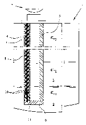
Fig. 1 is a schematic, cross-sectional view of a TDR fill-level detector
according
to a preferred embodiment of this invention, mounted on top of a container 1
filled with a
substance 2 over which a substance 3 is layered. The dielectric coefficient
E~, of the lower
substance 2 is less than the dielectric coefficient E~Z of the upper
substance. In typical
applications of the fill-level detector according to this invention, Er2 has a
value of 20 and
higher. Above the upper substance 3 there is a gas such as air with a
dielectric coefficient
of s~3. The TDR fill-level detector according to the preferred embodiment of
this
invention incorporates a first electrical conductor 4 and a second electrical
conductor 5.
Positioned at their ends outside the substance 2 is a partly outlined detector
enclosure 6 of
the TDR fill-level detector. The detector enclosure 6 houses a generator, not
shown,
serving to generate and transmit an electromagnetic signal which, in the
preferred
embodiment here described, is a short electric pulse used for the TDR fill-
level gaging, as
well as a transducer, not shown, for capturing a reflected portion of the
short electric
pulse.
Inside the first electrical conductor 4 is an inner conductor 7 which is
insulated
from the inner wall of the first electrical conductor 4 by means of a PTFE
jacket 8. By
way of a cross brace 9, the inner conductor 7 is connected in electrically
conductive
fashion to the end, positioned in the substance 2, of the second electrical
conductor S. A
spacer 11, provided with a seal 10, serves the dual purpose of sealing the
inside of the
first electrical conductor 4 and insulating the first electrical conductor 4
from the firmer
7
CA 02324172 2000-10-23
conductor 7 and the second electrical conductor 5. The first electrical
conductor 4, the
second electrical conductor 5 and the cross brace 9 consist of high-grade
stainless steel,
i.e. the first electrical conductor 4 is a rigid, metallic, tubular element.
This allows a short
electric pulse produced by the generator to be coupled into the inner
conductor 7 inside
the first electrical conductor 4 and to travel through the latter all the way
to its end
situated in the substance 2, without the short electric pulse making contact
with the
substance 2 or substance 3. Its rate of propagation thus corresponds to the
speed of light.
At the end of the first electrical conductor 4 in the substance 2, the short
electric pulse is
decoupled from the inner conductor 7 and transferred via the cross brace 9 to
the second
electrical conductor 5.
At the cross brace 9, exiting from the inner conductor 7, the short electric
pulse
which up to this point has traveled in a downward direction, is practically
reflected
upwards, reversing its path. The cross brace essentially serves as a "minor"
which
reverses the direction of travel of the short electric pulse. The short
electric pulse then
continues upward within the lower substance 2 between the second electrical
conductor 5
and the first electrical conductor 4, now serving as a reference conductor,
its rate of
propagation diminished as a function of the dielectric coefficient E~,.
The actual flow of the TDR fill-level measuring process employing a TDR fill-
level detector according to a preferred embodiment of this invention is
schematically
shown in Fig. 2 in time-sequential sub-steps t, to t,o. At time t,, the
generator housed in
8
CA 02324172 2000-10-23
the detector enclosure 6 produces a short electric pulse. Without making
electrical contact
with the first electrical conductor 4, the short electric pulse is coupled
into the inner
conductor 7 which in insulated fashion extends within the first electrical
conductor 4. In
essence, the core conductor of the coaxial cable which serves to forward the
short electric
pulse emanating from the pulse generator is thus directly connected to the
inner
conductor 7. The inner conductor 7, jointly with the first electrical
conductor 4,
essentially constitutes an extension of the coaxial cable carrying the short
electric pulse
from the generator. At the speed of light v,, the short electric pulse travels
inside the first
electrical conductor 4 to the end of the latter, situated in the lower
substance. As is
evident from the time indications t2, t3 and t4, the rate of propagation of
the short electric
pulse within the first electrical conductor 4 remains at the speed of light v,
regardless of
where the short electric pulse happens to be, i.e. regardless of which
substance surrounds
the first electrical conductor 4 at any one time, since the short electric
pulse, while in the
first electrical conductor 4, does not make contact with the externally
surrounding
substances. At time is the short electric pulse reaches the end of the first
electrical
conductor 4 situated in the lower substance 2 at which point it is decoupled
and
transferred to the second electrical conductor 5 which is connected in
electrically
conductive fashion to the inner conductor 7 by way of the cross brace 9. The
short electric
pulse is then fiu~ther propagated at the reduced rate va corresponding to the
dielectric
coefficient s~, of the lower substance 2 and travels upward between the first
electrical
conductor 4 and the second electrical conductor S. At time tb, the short
electric pulse
reaches the interface between the lower substance 2 and the upper layer of
substance 3.
9
CA 02324172 2000-10-23 _
Due to the high dielectric constant s~z of the substance 3, typically more
than 20, only a
small portion of the short electric pulse penetrates into the substance 3
while the major
portion of the short electric pulse is reflected at the interface between the
substance 2 and
the substance 3, resuming its downward path at the rate vz corresponding to
the dielectric
constant E~, of the substance 2. At the end of the first electrical conductor
4, situated in the
substance 2, the reflected portion of the short electric pulse is then coupled
back into the
inner conductor 7 within the first electrical conductor 4 where it travels
along the inner
conductor 7, at the speed of light v,, over the entire distance from the end
of the first
electrical conductor 4 in the substance 2 to the transducer housed in the
detector
enclosure 6. Finally, at time t,o, the reflected portion of the electric pulse
is captured by
the transducer.
Since the length of the first electrical conductor, meaning the distance from
the
generator or transducer to the end of the first electrical conductor 4 in the
substance 2, the
dielectric constant s~, of the lower substance 2 and the speed of light v, are
known factors,
the total runtime of the short electric pulse and that of its reflected
portion from the
generator to the interface between the lower substance 2 and the upper
substance 3 and
_ back to the transducer will be indicative of the fill level of the second
substance 2.
If the dielectric constant s~, of the substance 2 is not known from the start,
it can
be determined by means of a conventional TDR fill-level gaging procedure,
provided the
substance 3 is not yet layered on top of the substance 2, or by another
conventional
process such as a capacitive measurement, or it can be determined by means of
the
process according to this invention if the fill-level of the lower substance 2
is known.
CA 02324172 2000-10-23
Hence, the only calibration parameters required for installing the TDR fill-
level detector
according to this invention are the dielectric constant of the lower substance
2 and the
length of the first electrical conductor 4.
The preferred embodiment of this invention, described above, pertains to a TDR
fill-level detector, i.e. a TDR fill-level gaging procedure employing short
electric pulses
as the electromagnetic signal. Of course, this invention is equally suitable
for use with a
p fill-level detector or fill-level gaging procedure employing as the
electromagnetic signal
continuous electromagnetic waves, thus including for instance an FM-CW
process.
11