Sélection de la langue

Search

Sommaire du brevet 2324763 

Énoncé de désistement de responsabilité concernant l'information provenant de tiers

Une partie des informations de ce site Web a été fournie par des sources externes. Le gouvernement du Canada n'assume aucune responsabilité concernant la précision, l'actualité ou la fiabilité des informations fournies par les sources externes. Les utilisateurs qui désirent employer cette information devraient consulter directement la source des informations. Le contenu fourni par les sources externes n'est pas assujetti aux exigences sur les langues officielles, la protection des renseignements personnels et l'accessibilité.

Disponibilité de l'Abrégé et des Revendications

L'apparition de différences dans le texte et l'image des Revendications et de l'Abrégé dépend du moment auquel le document est publié. Les textes des Revendications et de l'Abrégé sont affichés :

  • lorsque la demande peut être examinée par le public;
  • lorsque le brevet est émis (délivrance).
(12) Demande de brevet: (11) CA 2324763
(54) Titre français: PISTON POUR FERMER UNE CARTOUCHE
(54) Titre anglais: PISTON FOR CLOSING A CARTRIDGE
Statut: Réputée abandonnée et au-delà du délai pour le rétablissement - en attente de la réponse à l’avis de communication rejetée
Données bibliographiques
(51) Classification internationale des brevets (CIB):
  • B65D 83/76 (2006.01)
  • B65D 83/00 (2006.01)
(72) Inventeurs :
  • STOSSEL, WILLY (Suisse)
(73) Titulaires :
  • STEBLER U. CO. AG
(71) Demandeurs :
  • STEBLER U. CO. AG (Suisse)
(74) Agent: NORTON ROSE FULBRIGHT CANADA LLP/S.E.N.C.R.L., S.R.L.
(74) Co-agent:
(45) Délivré:
(22) Date de dépôt: 2000-10-31
(41) Mise à la disponibilité du public: 2001-07-11
Licence disponible: S.O.
Cédé au domaine public: S.O.
(25) Langue des documents déposés: Anglais

Traité de coopération en matière de brevets (PCT): Non

(30) Données de priorité de la demande:
Numéro de la demande Pays / territoire Date
0046/00 (Suisse) 2000-01-11

Abrégés

Abrégé anglais


Known cartridges have a cylindrical container
part comprising an outlet nozzle arranged at the front,
closed end and a piston inserted into the orifice in the
rear end and movable in the longitudinal direction of
the cartridge and intended for sealing the interior of
the cartridge and ejecting the flowable material. The
invention relates to such a piston (6). This is
essentially in the form of a cylinder which is closed at
one end and whose external diameter is at least as large
as the internal diameter of the cylindrical container
part. It is thus dimensioned so that, for closing the
cartridge, it is pressed with a tight fit into the
container part. The cylindrical sidewall (8) of the
press piston (6) is in addition provided with at least
one bevel (11) starting from the end wall (7), so that,
when the piston (6) is pressed into the container part
of the cartridge, the at least one bevel (11), together
with the cylindrical wall of the container part, briefly
forms a passage through which the air displaced by the
piston can escape outwards, and that consequently no
residual air remains in the cartridge and triggers
undesirable hardening of the flowable material inside
the container part.

Revendications

Note : Les revendications sont présentées dans la langue officielle dans laquelle elles ont été soumises.


8
CLAIMS
1. Piston for insertion into the cylindrical
container part (2) of a cartridge (1) which serves for
holding a flowable material and comprises a cylindrical
sidewall (8) and an end wall (7), wherein the external
diameter of the cylindrical sidewall (8) of the piston
(6) is at least as large as the internal diameter of the
cylindrical container part (2) of the cartridge (1) and
wherein the cylindrical sidewall (8) is provided with at
least one bevel (11) starting from the end wall (7) and
is dimensioned in such a way that it can be pressed with
a tight fit into the container part (2) and that, when
the piston (6) is pressed in, the at least one bevel
(11), together with the cylindrical wall of the
container part (2) briefly forms a passage through which
the air displaced by the piston (6) can escape outwards.
2. Piston according to Claim 1, wherein at least
two, preferably four or six, bevels (11) distributed
symmetrically around the circumference of the
cylindrical sidewall (8) are present.
3. Piston according to Claim 1 or 2, comprising a
cylinder section (10) which has the at least one bevel
(11) and whose length is at least 1/4 and not more than
2/3 of the total length of the cylindrical sidewall (8).
4. Piston according to anyone of Claims 1 to 3,
wherein the external diameter of the cylindrical
sidewall (8) is not more than 2% greater than the
internal diameter of the cylindrical container part (2).

7
5. Piston according to anyone of Claims 1 to 4,
wherein the at least one bevel (11) becomes narrower
with increasing distance from the end wall (7).
6. Piston according to anyone of Claims 1 to 5,
wherein it consists of aluminium.

Description

Note : Les descriptions sont présentées dans la langue officielle dans laquelle elles ont été soumises.

CA 02324763 2000-10-31
Stebler & Co. AG, Nunningen
Piston for closing a cartridge
DESCRIPTION
The invention relates to a piston for closing or
sealing a cartridge, namely a piston according to the
precharacterizing clause of Claim 1.
Cartridges are intended for holding a flowable
material and are used, for example, wherever a possibly
moisture-sensitive, flowable material has to be applied
in portions in grooves, joints and the like. The
cartridges used in building and in industry are produced
today in particular from aluminium. They have a
cylindrical container part with an outlet nozzle
arranged at the front end and a piston inserted into the
orifice in the rear end and movable in the longitudinal
direction of the cartridge and intended for sealing the
interior of the cartridge and ejecting the flowable
material. The material is usually ejected by using a
hand-operated injection gun with a plunger which is
tailored to the piston and moves the piston towards the
outlet nozzle when the cartridge is used.
In a known method for closing filled cartridges,
the inner surface of the cylindrical container part is
provided, in the region of the rear end section, with an
all-round wax layer serving as a sealant, and
subsequently a piston whose external diameter is smaller
than the internal diameter of the container part is
inserted into the container part. This has the advantage
that, when the piston is inserted, the air present in
the interior of the cartridge and displaced by the
Ks/20162/case 4

CA 02324763 2000-10-31
2
piston can readily escape outwards, but, on the other
hand, the disadvantage that for a fluid- and gas-tight
seal, the piston inserted into the container part must
subsequently also be pressed, i.e. expanded, by the
container part, which is usually effected by means of an
expanding device specially provided for this purpose.
It is the object of the invention to provide a
novel piston for cartridges of the above-mentioned type
which makes it possible to simplify the fluid- and gas-
tight sealing of the cartridge in such a way that it is
possible to dispense with the expansion, i.e. with the
additional use of an expansion device.
This object is achieved by a piston having the
features of Patent Claim 1.
Advantageous embodiments of the invention form
the subject of the dependent Claims.
The novel piston, also referred to below as
press piston, is distinguished essentially by the fact
that it is in the form of a cylinder which is closed at
one end and whose external diameter is also at least as
large as the internal diameter of the cylindrical
container part. The piston according to the invention is
thus dimensioned so that it already has a tight fit when
inserted into the container part. Although this is not
possible without additional application of force, it can
readily be effected, by means of a conventional, axially
operating press device. The advantage of this procedure
is obvious. Thus, it is possible to dispense with the
subsequent expansion of the piston by means of a device

CA 02324763 2000-10-31
. 3
specially provided for this purpose.
In addition, the cylindrical sidewall of the
piston according to the invention is provided with at
least one bevel starting from the end face, so that,
when the piston is pressed into the container part of
the cartridge, the at least one bevel, together with the
cylindrical wall of the container part, briefly forms a
passage through which the air displaced by the piston
can escape outwards, and that consequently no excess
pressure adversely affecting the tightness of the
cartridge is generated in the interior of the cartridge
and in particular no residual air remains in the
cartridge and triggers a chemical reaction, for example
undesired hardening of the flowable material inside the
container part.
The press pistons according to the invention
preferably consist of metallic material, for example of
tin plate or aluminium.
It is expedient to provide at least two,
preferably four or six, bevels arranged symmetrically
with respect to one another. Such an embodiment of the
press piston according to the invention leads to optimum
venting of the cartridge when the piston is pressed into
the container part, and does so with constant moisture
and sealing properties so that the shelf-life and
operational safety of cartridges sealed by means of
press pistons according to the invention is ensured.
The bevels according to the invention do not
cover the total circumference of the cylindrical

CA 02324763 2000-10-31
4
sidewall and are - as is evident from the drawing
explained below - essentially dent-like recesses in the
cylindrical sidewall.
An embodiment of the invention is described
below with reference to the attached drawing. In the
drawing,
Figure 1'shows a cartridge for holding a high-
viscosity or low-viscosity material and a press piston
intended to be inserted into the cartridge,
Figure 2 shows a plan view of the end face of the
press piston according to the invention and shown on a
larger scale, and
Figure 3 shows a section along the line III of
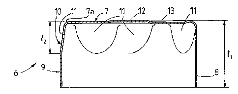
Figure 2.
The cartridge shown in Figure 1 is denoted as a
whole by 1 and has a cylindrical container part 2 for
holding a flowable material, such as, for example, a
polyurethane-containing sealant. The container part 2
has an end face 3 with an outlet nozzle 4. The latter
preferably has an external thread 4a, onto which an
outlet tip, which is not shown, is screwed for using the
cartridge 1.
That end 5 of the container part 2 which is
opposite the end face 3 is open and, after the cartridge
1 has been filled, is closed fluid- and gas-tight with
the press piston 6 according to the invention.

CA 02324763 2000-10-31
5
The press piston 6 shown on a larger scale in
Figures 2 and 3 preferably consists of aluminium and has
an end wall 7 intended for facing the outlet 4 of the
cartridge 1 and an essentially cylindrical sidewall 8
having the length 11. The latter is divided into a first
cylinder section 9 facing away from the end wall 7 and a
second cylinder section 10 facing the end wall 7.
The wall thickness of the press piston 6 is
0.2 mm - 1 mm, but preferably 0.4 mm. No subsequent
expansion of the piston 6 is necessary for the fluid-
and gas-tight sealing of the interior of the cartridge,
said piston has an external diameter which is at least
as large as the internal diameter of the cylindrical
container part 2, but is not more than about 20, for
example 1%, larger than said internal diameter.
As is clearly evident in particular from Figure
3, the second cylinder section 10 is provided with six
bevels 11 which are arranged symmetrically around the
circumference of the cylinder section 10, start from the
end edge 7a and extend over the entire length of the
cylinder section 10, and become narrower with increasing
distance from the rounded end edge 7a.
The length 12 of the second cylinder section 10
is preferably. chosen so that the relationship
1/411 <_ 12 <_ 2/3 ~ 11
is fulfilled. Thus, the length 12 of the cylinder section
10 is always at least 1/4 and not more than 2/3 of the
total length 11.
The cylinder section 9 serves essentially for

CA 02324763 2000-10-31
6
sealing the interior of the cartridge. It must therefore
have a sidewall area which is so large that the interior
of the cartridge is optimally sealed even during
displacement of the piston 6. The cylinder section 9 is
therefore preferably at least as large as the cylinder
section 10.
The sidewall 8 as a whole must moreover be so
long that the~piston 6 retains its axial orientation
when the material is being forced out of the cartridge 1
and does not adopt a skew position.
From the drawing, it is also evident that the
press piston 6 has, on its end face 7, a central,
circular bulge 12 and six radially arranged notches 13
which extend outwards from the bulge 12 and in turn are
oriented symmetrically so that their axial extensions
are in each case between two adjacent bevels 11. Both
the bulge 12 and the notches 13 serve essentially for
forming a dimensionally rigid and stable end wall 7
which withstands the pressure of the injection gun used
for holding the cartridge.
Below, the use of the press piston according to
the invention is described briefly.
In a first step, the container part 2
additionally having a wax layer in the rear end section
5 is filled with flowable material.
The container part 2 is then fed to a press
which is coordinated with the filling or closing line
and by means of which a piston 6 is pressed into the

CA 02324763 2000-10-31
7
open end section 5 of the container part 2. The material
of container part 2 and piston 6 should furthermore be
tailored to one another in such a way that, if the
external diameter of the piston 6 is slightly larger
than the internal diameter of container part, the
cylindrical wall of the container part slightly deforms
and expands when the piston 6 is pressed in.
When the piston 6 is pressed in, the air present
in the interior of the cartridge and displaced by the
penetrating piston 6 escapes outwards through passages
briefly formed by the bevels 11, so that no excess
pressure is generated in the interior of the cartridge,
and the piston 6 thus remains in the inserted state.
Both the wall thicknesses and the dimensions of
the internal diameter and external diameter of the
container part 2 and piston 6, respectively, should be
tailored to one another so that a fluid- and gas-tight
seal is ensured. The above-mentioned wall thicknesses
and dimensions of the press piston according to the
invention are therefore empirical values which arise
from the numerous tests and may differ with a different
choice of material and cartridge size. Pistons according
to the invention may therefore have shapes and
dimensions differing from the embodiment shown.

Dessin représentatif
Une figure unique qui représente un dessin illustrant l'invention.
États administratifs

2024-08-01 : Dans le cadre de la transition vers les Brevets de nouvelle génération (BNG), la base de données sur les brevets canadiens (BDBC) contient désormais un Historique d'événement plus détaillé, qui reproduit le Journal des événements de notre nouvelle solution interne.

Veuillez noter que les événements débutant par « Inactive : » se réfèrent à des événements qui ne sont plus utilisés dans notre nouvelle solution interne.

Pour une meilleure compréhension de l'état de la demande ou brevet qui figure sur cette page, la rubrique Mise en garde , et les descriptions de Brevet , Historique d'événement , Taxes périodiques et Historique des paiements devraient être consultées.

Historique d'événement

Description Date
Demande non rétablie avant l'échéance 2006-10-31
Le délai pour l'annulation est expiré 2006-10-31
Inactive : CIB de MCD 2006-03-12
Réputée abandonnée - omission de répondre à un avis sur les taxes pour le maintien en état 2005-10-31
Inactive : Abandon.-RE+surtaxe impayées-Corr envoyée 2005-10-31
Inactive : Page couverture publiée 2001-07-22
Demande publiée (accessible au public) 2001-07-11
Inactive : CIB en 1re position 2001-01-24
Demande reçue - nationale ordinaire 2000-12-07
Lettre envoyée 2000-12-07
Inactive : Certificat de dépôt - Sans RE (Anglais) 2000-12-07

Historique d'abandonnement

Date d'abandonnement Raison Date de rétablissement
2005-10-31

Taxes périodiques

Le dernier paiement a été reçu le 2004-09-21

Avis : Si le paiement en totalité n'a pas été reçu au plus tard à la date indiquée, une taxe supplémentaire peut être imposée, soit une des taxes suivantes :

  • taxe de rétablissement ;
  • taxe pour paiement en souffrance ; ou
  • taxe additionnelle pour le renversement d'une péremption réputée.

Les taxes sur les brevets sont ajustées au 1er janvier de chaque année. Les montants ci-dessus sont les montants actuels s'ils sont reçus au plus tard le 31 décembre de l'année en cours.
Veuillez vous référer à la page web des taxes sur les brevets de l'OPIC pour voir tous les montants actuels des taxes.

Historique des taxes

Type de taxes Anniversaire Échéance Date payée
Taxe pour le dépôt - générale 2000-10-31
Enregistrement d'un document 2000-10-31
TM (demande, 2e anniv.) - générale 02 2002-10-31 2002-09-18
TM (demande, 3e anniv.) - générale 03 2003-10-31 2003-09-12
TM (demande, 4e anniv.) - générale 04 2004-11-01 2004-09-21
Titulaires au dossier

Les titulaires actuels et antérieures au dossier sont affichés en ordre alphabétique.

Titulaires actuels au dossier
STEBLER U. CO. AG
Titulaires antérieures au dossier
WILLY STOSSEL
Les propriétaires antérieurs qui ne figurent pas dans la liste des « Propriétaires au dossier » apparaîtront dans d'autres documents au dossier.
Documents

Pour visionner les fichiers sélectionnés, entrer le code reCAPTCHA :


Pour visualiser une image, cliquer sur un lien dans la colonne description du document (Temporairement non-disponible). Pour télécharger l'image (les images), cliquer l'une ou plusieurs cases à cocher dans la première colonne et ensuite cliquer sur le bouton "Télécharger sélection en format PDF (archive Zip)" ou le bouton "Télécharger sélection (en un fichier PDF fusionné)".

Liste des documents de brevet publiés et non publiés sur la BDBC .

Si vous avez des difficultés à accéder au contenu, veuillez communiquer avec le Centre de services à la clientèle au 1-866-997-1936, ou envoyer un courriel au Centre de service à la clientèle de l'OPIC.

({010=Tous les documents, 020=Au moment du dépôt, 030=Au moment de la mise à la disponibilité du public, 040=À la délivrance, 050=Examen, 060=Correspondance reçue, 070=Divers, 080=Correspondance envoyée, 090=Paiement})


Description du
Document 
Date
(aaaa-mm-jj) 
Nombre de pages   Taille de l'image (Ko) 
Dessin représentatif 2001-07-19 1 5
Dessins 2000-10-30 1 20
Description 2000-10-30 7 246
Abrégé 2000-10-30 1 31
Revendications 2000-10-30 2 44
Courtoisie - Certificat d'enregistrement (document(s) connexe(s)) 2000-12-06 1 113
Certificat de dépôt (anglais) 2000-12-06 1 164
Rappel de taxe de maintien due 2002-07-02 1 114
Rappel - requête d'examen 2005-07-03 1 115
Courtoisie - Lettre d'abandon (requête d'examen) 2006-01-08 1 166
Courtoisie - Lettre d'abandon (taxe de maintien en état) 2005-12-27 1 174