Sélection de la langue

Search

Sommaire du brevet 2324812 

Énoncé de désistement de responsabilité concernant l'information provenant de tiers

Une partie des informations de ce site Web a été fournie par des sources externes. Le gouvernement du Canada n'assume aucune responsabilité concernant la précision, l'actualité ou la fiabilité des informations fournies par les sources externes. Les utilisateurs qui désirent employer cette information devraient consulter directement la source des informations. Le contenu fourni par les sources externes n'est pas assujetti aux exigences sur les langues officielles, la protection des renseignements personnels et l'accessibilité.

Disponibilité de l'Abrégé et des Revendications

L'apparition de différences dans le texte et l'image des Revendications et de l'Abrégé dépend du moment auquel le document est publié. Les textes des Revendications et de l'Abrégé sont affichés :

  • lorsque la demande peut être examinée par le public;
  • lorsque le brevet est émis (délivrance).
(12) Brevet: (11) CA 2324812
(54) Titre français: DISPOSITIF DE COLLECTE DE REBUTS ORGANIQUES AVEC UN CONDUIT SOUFFLEUR COURBE
(54) Titre anglais: ORGANIC DEBRIS COLLECTION DEVICE WITH CURVED BLOWER CONDUIT
Statut: Durée expirée - au-delà du délai suivant l'octroi
Données bibliographiques
(51) Classification internationale des brevets (CIB):
  • F16L 43/00 (2006.01)
  • F04D 23/00 (2006.01)
  • F04D 27/02 (2006.01)
(72) Inventeurs :
  • WHITNEY, JAMES C. (Etats-Unis d'Amérique)
(73) Titulaires :
  • WOODLAND POWER PRODUCTS, INC.
(71) Demandeurs :
  • WOODLAND POWER PRODUCTS, INC. (Etats-Unis d'Amérique)
(74) Agent: BORDEN LADNER GERVAIS LLP
(74) Co-agent:
(45) Délivré: 2004-09-14
(22) Date de dépôt: 2000-10-25
(41) Mise à la disponibilité du public: 2001-09-21
Requête d'examen: 2000-10-25
Licence disponible: S.O.
Cédé au domaine public: S.O.
(25) Langue des documents déposés: Anglais

Traité de coopération en matière de brevets (PCT): Non

(30) Données de priorité de la demande:
Numéro de la demande Pays / territoire Date
09/531,614 (Etats-Unis d'Amérique) 2000-03-21

Abrégés

Abrégé français

Un conduit d'échappement souffleur courbé, fournissant un courant d'air transportant des solides entraînés réduits en poudre ou granulés dans une chambre close de cargaison substantiellement scellée et de volume fixe, est doté d'un tuyau de ventilation à pression monté sur une région périphérique « interne » du tube courbé ayant un rayon de courbure plus petit que la région périphérique externe du conduit, reliant ainsi l'intérieur du tube courbé vers l'atmosphère externe à un point où la majorité des matières solides entraînées est transportée à proximité de la région périphérique externe par le courant d'air.


Abrégé anglais

A curved blower exhaust conduit, delivering an air stream carrying pulverized or granulated entrained solids to a substantially sealed cargo chamber enclosure of fixed volume, is provided with a pressure relief vent mounted at an "inner" peripheral region of the curved conduit having a smaller radius of curvature than the outer peripheral region of the conduit, thereby connecting the interior of the curved conduit to the external atmosphere at a point where the majority of entrained solids are carried adjacent to the outer peripheral region by the air stream.

Revendications

Note : Les revendications sont présentées dans la langue officielle dans laquelle elles ont été soumises.


THE EMBODIMENTS OF THE INVENTION IN WHICH AN EXCLUSIVE
PROPERTY OR PRIVILEGE IS CLAIMED ARE DEFINED AS FOLLOWS:
1. A curved blower conduit vented for pressure
relief, having an entrance end connectable to the outlet
portal of a blower and an exit end connectable to the inlet
portal of a cargo container, for carrying the blower's exhaust
air stream to the cargo container, comprising in combination:
a curved sector conduit extending between and
joining said entrance end and said exit end,
attachment means mounted on said sector conduit near
said ends for securing said connections,
an outer peripheral portion of said sector conduit
having a first radius of curvature,
an inner peripheral portion of said sector conduit
having a second radius of curvature
substantially smaller than said first radius of
curvature, and
means forming a vent connecting the interior of
said sector conduit, at a point of said inner peripheral
portion intermediate between said entrance end and said exit
end, to the external atmosphere,
whereby the blower's exhaust air stream is concentrated near
the outer peripheral sector conduit portion, relieving
pressure in said cargo container by directing any return flow
stream along the inner peripheral conduit portion and out

through said vent.
2. The curved blower conduit defined in Claim 1
wherein said curved sector conduit's vent means provides the
sole connection between the interior of said cargo container
and the atmosphere, said cargo container being otherwise a
substantially sealed chamber.
3. The curved blower conduit defined in Claim 1
wherein said curved sector conduit's vent means provides an
extra connection between the interior of said cargo container
and the atmosphere, supplementing air escape mesh means
incorporated in the cargo container itself.
4. The curved blower conduit defined in Claim 1
wherein said cargo container is a flexible fabric bag.
5. The curved blower conduit defined in Claim 1
wherein said cargo container is formed of rigid metal.
6. The curved blower conduit defined in Claim 1
wherein said cargo container is formed of rigid plastic.
7. The curved blower conduit of Claim 1 wherein
said conduit is arched upwardly and said vent means comprises
a laterally extending vent conduit anchored to the underside
11

of the upwardly arched sector conduit and having open ends
exposed laterally and an enlarged central opening connecting
the vent conduit to the sector conduit in the region where the
two conduits are anchored together.
8. The curved blower conduit of Claim 7 wherein the
vent conduit's enlarged central opening occupies substantially
the entire width of the curved sector conduit in the region
where the two conduits are anchored together.
9. The curved blower conduit of Claim 1 wherein the
cross-section of the curved sector conduit is substantially
uniform over the majority of its length.
10. The curved blower conduit of Claim 9, wherein
the substantially uniform cross-section of the curved sector
conduit is approximately a square cross-section over the
majority of its length.
11. The curved blower conduit of Claim 7 wherein
the vent conduit and the blower sector conduit have separate,
non-overlapping cross-sections.
12. The curved blower conduit of Claim 11 wherein a
radial cross-section through the vent conduit and the sector
conduit exhibits an inverted "T" shape.
12

13. The curved blower conduit of Claim 1 wherein
the entrance end and the exit end of the curved sector conduit
define a sector angle of about 75°.
13

Description

Note : Les descriptions sont présentées dans la langue officielle dans laquelle elles ont été soumises.

CA 02324812 2000-10-25
This invention relates to vents formed at the minimum
inner radius of curvature of a curved blower exhaust conduit
through which entrained solid particles are carried by an
advancing stream of air, and more particularly to such vents
formed in a blower conduit carrying organic debris, leaves,
twigs, grass clippings and the like from a blower fan to a debris
collector enclosure or bag, minimizing internal pressure in the
collector and expediting the deposit of debris in the collector
enclosure.
These vents are improvements on the blower exhaust
conduits illustrated and described in my U.S. Patent 6,029,312,
issued Feb. 29, 2000, and U.S. Patent 6,003,195 issued Dec. 21,
1999.
The collection of leaves, grass clippings and other
organic debris from lawn mowers into either fabric collector
bags, or into rigid containers of metal or plastic, is well
known.
However, in order to keep the air stream, and its
attendant debris moving, means must be provided for venting the
high-velocity air. In vacuum cleaners and lawnmowers which
employ collector bags, this is commonly done by using a bag of
porous weave which permits the air to perfuse through the fabric.
However, as the bag fills up, the pores become clogged with
debris which substantially blocks the air flow and greatly
reduces the vacuum effect, sometimes reducing it to near zero.
In addition, when such fabric bags become clogged, they are
subjected to high internal pressure from the blower air stream.
i

CA 02324812 2000-10-25
If the blower is very powerful, the bag can rip apart at the
seams.
If the weave of the bag is made larger to avoid
clogging, a great quantity of material is lost through the mesh,
and the equipment operator may be exposed to quantities of
choking dust and debris particles. Furthermore, the higher air
pressure inside the bag tends to "plaster" the leaves, grass and
other debris against the inside of the mesh, effectively blocking
the air flow and reducing the vacuum effect.
In yet other types of lawn vacuum equipment, the
collector container is made of rigid metal or plastic, or solid
weave fabric which does not breathe at a11. In all such cases,
either a clear opening or an open-mesh screen must be provided
to vent the air, in order to provide the vacuum effect. These
arrangements have just the same problems as described above.
Either a great quantity of material is lost through the vent
area, or the vent mesh itself clogs from the higher inside air
pressure, which forces the debris against the vent screen, thus
reducing or eliminating the vacuum effect.
It has now been discovered that one or more vents
diverting a portion of the blower exhaust stream downward or
sidewise, transverse to its direction of travel through an
upwardly arched curved sector of the blower delivery conduit,
will almost completely eliminate the problems described above.
With this arrangement it is possible to completely fill a
collector container of any type, whether solid metal, rigid
2

CA 02324812 2000-10-25
plastic, or closed mesh fabric, even when the container has no
venting means or vent screen at all. Nearly full vacuum effect
is maintained all the way to the top of the collector container,
with virtually no escape of debris. In addition, the high
internal pressure which can develop inside a vent-clogged
collector bag or container is substantially reduced. The effect
is quite startling when observed in actual operation.
In organic material collection systems, the relief
vents are preferably formed in the curved delivery conduit's
lower wall near the smallest radius of curvature on the "inside"
of the curve. Since the curved delivery conduit is often
convexly arched upward, a vent facing directly downward would
cause a downdraft like a helicopter's downwash, scattering
organic debris on the ground below the blower and trailer which
ideally should remain in place until it is drawn in by the blower
and delivered to the collector bag. The vents shown in the
drawings divert and eject air sidewise, away from the vicinity
of the blower, the operator and the collector bag, reducing to
a minimum the scattering of debris.
3

CA 02324812 2000-10-25
The entrained organic particles in the air stream are
believed to be carried by the "outside" maximum radius region of
the curved sector of the delivery conduit, and venting the
"inside" minimum radius region of the curved sector releases very
few entrained particles or bits of debris.
Accordingly, a principal object of the invention is to
maximize the effectiveness of blower-driven air streams carrying
entrained organic debris into a collector enclosure by
eliminating the need for venting the air flow from inside the
collector container, and thereby eliminating the problems of
debris escape, vent mesh clogging, and the loss of vacuum effect
described above.
Another object is to reduce the pressure developed
inside the collector container which results when the air escape
path is completely blocked. This is particularly important in
fabric collector bags, which can be over stressed or even torn
apart by blower pressure if the vents become clogged.
Still another object is to form vents in the delivery
conduit, ejecting air from a curved region of the conduit while
minimizing ejection of entrained particles therefrom.
Other objects of the invention will in part be obvious
and will in part appear hereinafter.
4

CA 02324812 2000-10-25
The invention accordingly comprises the features of
construction, combination of elements, and arrangement of parts
which will be exemplified in the construction hereinafter set
forth, and the scope of the invention will be indicated in the
claims.
For a fuller understanding of the nature and objects
of the invention, reference should be made to the following
detailed description taken in connection with the accompanying
drawings, in which:
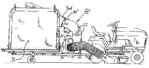
FIGURE 1 is a side elevation view of a lawn mowing
tractor towing a trailer which carries a blower having an exhaust
conduit delivering organic debris to a fabric collector bag also
carried on the trailer;
FIGURE 2 is a perspective view of the trailer showing
the blower, the exhaust conduit and the collector bag all carried
on the trailer;
FIGURE 3 is a rear elevation view of the exhaust
conduit of FIGURE 1, showing the dual exhaust vents formed in its
underside;
FIGURE 4 is a side elevation view, partially in cross
section showing flow paths of the blower's exhaust air stream
carrying entrained debris, and back-pressure eddies on the
smaller radius inside portion of the exhaust conduit's curved
sector;
5

CA 02324812 2000-10-25
FIGURE 5 is a front elevation view of the exhaust
conduit; and
FIGURE 6 is an enlarged cross-sectional rear oblique
view of the exhaust conduit taken along the line 6-6 in FIGURE
4, showing the interior of the conduit opening directly into the
lateral exhaust vents.
Blower exhaust conduits 20 incorporating two back-
pressure diverting relief vents 21 are shown in the FIGURES.
Each exhaust conduit 20 may have any desired cross-sectional
shape. The conduits shown in FIGURES 1 through 6 have a square
cross-section at their lower intake ends, carrying latches 22
which removably attach each conduit in its operative position,
overlying the upward facing exhaust portal 23 of blower 24.
The sidewalls 26 of conduit 20 are substantially flat
and parallel. The upper wall 27 is convexly curved as shown in
the FIGURES, bending rearwardly toward the collector bag 31, and
an intake shroud 34 is detachably secured by snap tabs 35 to
snaps 36 mounted on the round upper exit end of curved conduit
(FIGS. 1, 2) .
20 As shown in the FIGURES, pressure relief vents 21 may
be formed as a laterally extending vent tube 25, which may be of
trapezoidal cross-section with its widest face 28 facing upward,
integrally joined to the lowest portion of sidewalls 26 along a
junction 30 (FIGURE 6). Lower wall 29 of conduit 20 is spaced
below upper wall 27, defining a curved interior passage of
6

CA 02324812 2000-10-25
generally uniform cross-section, bounded by side walls 26, upper
wall 27 and except in the region of relief vents 21 by lower wall
29.
As clearly shown in FIGURE 6, the upper face 28 of vent
tube 25 and the lower wall 29 of conduit 30 do not extend across
conduit 20 between the two junctions 30. Instead the interior
of conduit 20 opens without obstruction into the interior of
relief vent tube 25, whose lateral ends 33 form relief vents 21,
open to the atmosphere.
At first glance, the casual observer might expect that
the blower driven debris stream 32 from blower 24 would be
diverted and expelled from both ends 33 of the relief vent tube
25, and would never reach collector bag 31.
It has been discovered, however, that only a negligible
quantity of debris exits sidewise from the ends 33 of vent tube
25, while pressure in collector bag 31 is significantly reduced,
and greater than expected volumes of leaves, grass clippings and
similar organic debris are collected and effectively packed down
in collector bag 31. It is believed that the debris-laden
blower-driven air stream 32, traveling through the curved conduit
20 and represented by elongated arrows in FIGURE 4 and by leaves
shown in FIGURE 6, is concentrated in the upper half of conduit
20 near upper arched wall 27 at the "outside" of the bend in the
curved conduit 20, thus reducing the velocity of the air stream
at the "inside" of the bend in curved conduit 20, near relief
7

CA 02324812 2000-10-25
vents 21.
This is believed to be analogous to the flow
characteristics at the bend in a river channel, where centrifugal
force causes the fastest current and the highest flow rate in
gallons per minute to occur at the outside of the bend, while
stagnant flow and reverse eddies are observed at the inside of
the bend. This sometimes produces shoaling of the river bed at
the inside of the bend, causing deep-draft vessels to steer near
the outside of the bend, to avoid grounding.
Stagnant flow and eddies near vents 21 on the "inside"
of the bend in conduit 20 are believed to account for the reduced
back-pressure found in collector bag 31, and for the
insignificant amount of debris escaping from vents 21, on the
"inside" of the bend in conduit 20.
It will thus be seen that the objects set forth above,
and those made apparent from the preceding description, are
efficiently attained and, since certain changes may be made in
the above construction without departing from the scope of the
invention, it is intended that all matter contained in the above
description or shown in the accompanying drawings shall be
interpreted as illustrative and not in a limiting sense.
8

CA 02324812 2000-10-25
It is also to be understood that the following claims
are intended to cover all of the generic and specific features
of the invention herein described, and all statements of the
scope of the invention which, as a matter of language, might be
said to fall therebetween.
9

Dessin représentatif
Une figure unique qui représente un dessin illustrant l'invention.
États administratifs

2024-08-01 : Dans le cadre de la transition vers les Brevets de nouvelle génération (BNG), la base de données sur les brevets canadiens (BDBC) contient désormais un Historique d'événement plus détaillé, qui reproduit le Journal des événements de notre nouvelle solution interne.

Veuillez noter que les événements débutant par « Inactive : » se réfèrent à des événements qui ne sont plus utilisés dans notre nouvelle solution interne.

Pour une meilleure compréhension de l'état de la demande ou brevet qui figure sur cette page, la rubrique Mise en garde , et les descriptions de Brevet , Historique d'événement , Taxes périodiques et Historique des paiements devraient être consultées.

Historique d'événement

Description Date
Inactive : Périmé (brevet - nouvelle loi) 2020-10-26
Représentant commun nommé 2019-10-30
Inactive : CIB expirée 2018-01-01
Inactive : CIB de MCD 2006-03-12
Accordé par délivrance 2004-09-14
Inactive : Page couverture publiée 2004-09-13
Inactive : Grandeur de l'entité changée 2004-07-13
Préoctroi 2004-06-28
Inactive : Taxe finale reçue 2004-06-28
Un avis d'acceptation est envoyé 2004-01-19
Lettre envoyée 2004-01-19
Inactive : Approuvée aux fins d'acceptation (AFA) 2004-01-06
Demande publiée (accessible au public) 2001-09-21
Inactive : Page couverture publiée 2001-09-20
Lettre envoyée 2001-02-28
Inactive : Transfert individuel 2001-02-06
Inactive : CIB en 1re position 2001-01-19
Inactive : Lettre de courtoisie - Preuve 2000-12-12
Inactive : Certificat de dépôt - RE (Anglais) 2000-12-08
Exigences de dépôt - jugé conforme 2000-12-08
Demande reçue - nationale ordinaire 2000-12-07
Exigences pour une requête d'examen - jugée conforme 2000-10-25
Toutes les exigences pour l'examen - jugée conforme 2000-10-25

Historique d'abandonnement

Il n'y a pas d'historique d'abandonnement

Taxes périodiques

Le dernier paiement a été reçu le 2003-10-06

Avis : Si le paiement en totalité n'a pas été reçu au plus tard à la date indiquée, une taxe supplémentaire peut être imposée, soit une des taxes suivantes :

  • taxe de rétablissement ;
  • taxe pour paiement en souffrance ; ou
  • taxe additionnelle pour le renversement d'une péremption réputée.

Veuillez vous référer à la page web des taxes sur les brevets de l'OPIC pour voir tous les montants actuels des taxes.

Titulaires au dossier

Les titulaires actuels et antérieures au dossier sont affichés en ordre alphabétique.

Titulaires actuels au dossier
WOODLAND POWER PRODUCTS, INC.
Titulaires antérieures au dossier
JAMES C. WHITNEY
Les propriétaires antérieurs qui ne figurent pas dans la liste des « Propriétaires au dossier » apparaîtront dans d'autres documents au dossier.
Documents

Pour visionner les fichiers sélectionnés, entrer le code reCAPTCHA :


Pour visualiser une image, cliquer sur un lien dans la colonne description du document. Pour télécharger l'image (les images), cliquer l'une ou plusieurs cases à cocher dans la première colonne et ensuite cliquer sur le bouton "Télécharger sélection en format PDF (archive Zip)" ou le bouton "Télécharger sélection (en un fichier PDF fusionné)".

Liste des documents de brevet publiés et non publiés sur la BDBC .

Si vous avez des difficultés à accéder au contenu, veuillez communiquer avec le Centre de services à la clientèle au 1-866-997-1936, ou envoyer un courriel au Centre de service à la clientèle de l'OPIC.


Description du
Document 
Date
(aaaa-mm-jj) 
Nombre de pages   Taille de l'image (Ko) 
Dessin représentatif 2001-09-11 1 16
Abrégé 2000-10-25 1 16
Description 2000-10-25 9 283
Revendications 2000-10-25 4 95
Dessins 2000-10-25 2 85
Page couverture 2001-09-19 1 44
Dessin représentatif 2004-08-12 1 17
Page couverture 2004-08-12 1 45
Certificat de dépôt (anglais) 2000-12-08 1 164
Courtoisie - Certificat d'enregistrement (document(s) connexe(s)) 2001-02-28 1 113
Rappel de taxe de maintien due 2002-06-26 1 114
Avis du commissaire - Demande jugée acceptable 2004-01-19 1 161
Correspondance 2000-12-08 1 15
Correspondance 2004-06-28 1 38