Note : Les descriptions sont présentées dans la langue officielle dans laquelle elles ont été soumises.
CA 02325182 2000-11-07
FIELD OF INVENTION
The invention relates to a fire-protection sleeve for pipes, cables and the
like, formed of an axially extending tubular metal housing with a radially
outwardly extending flange at one end. A heat-intumescing composition is
located within the housing at the one end and encircles an opening through the
housing arranged to receive a pipe, cable and the like.
BACKGROUND OF THE INVENTION
Fire-protection sleeves are used as fire-protection elements for holes
through masonry walls, ceilings or floors of buildings. In the case of
combustible
or fusible pipes, cables and the like of plastics material, glass or aluminum,
the
sleeves are intended to close off openings in masonry, in order to prevent
penetration of fire through the opening. Known fire-protection sleeves usually
have a tubular configuration and are used, for example, as space holders in an
early building phase. In these cases, they are mounted on a form and cast into
the concrete. In this way, the concrete wall part is already provided with a
masonry opening. During the installation in a later building phase or during a
subsequent enlargement, fire-protection sleeves, as closing-off sleeves, are
inserted from one side into a previously produced opening in the masonry. The
known fire-protection sleeves have a metal or plastics material housing, into
which a sufficient amount of a heat-intumescing composition is integrated,
which
expands in the event of a fire and closes off the opening that results when
the
part or cable burns or melts away.
-1-
CA 02325182 2000-11-07
The larger the diameter of the opening that is to be closed off and the
higher the pressure resulting from the fire, the more difficult it is to close
off the
opening, during a fire. In addition;. in the event of a fire, the fire-
protection
sleeves with the heat-intumescing composition must be able to withstand the
pressure of the jet of extinguishing water, used by the firefighters. For this
purpose, systems are already known in the state of the art, for which the
intumescence of the composition integrated into the fire-protection sleeves,
is
actively supported by mechanical components, such as springs, flaps,
fiberglass
fabric, and the like. The main function of these mechanical components is to
support the slight expansion force of the heat-intumescing compositions or,
since
the latter are relatively expensive, to reduce the amount of intumescing
composition. The known mechanical aides fulfill their function satisfactorily
only
if the diameters of the openings are relatively small. In the case of larger
diameters, they are relatively unwieldy in use and make the fire-protection
sleeve
unduly more expensive.
The U.S. patent 4,888,925 discloses a sleeve-like pipe coupling, which is
placed in an opening in masonry. The pipe coupling has as a tubular inner
housing of plastics material with stops, which project into the interior, for
the
pipes, which are pushed in and are to be coupled. At one longitudinal end, the
interior housing is surrounded by an annular metallic casing. The annular
space
between the metal casing and the inner housing is filled with a heat-
intumescing
-2-
CA 02325182 2000-11-07
composition. Metal brackets, radially projecting from the casing to the
tubular
inner housing, form the boundary of the annular space at the one longitudinal
end of the pipe coupling. The radially extending brackets are to prevent the
emergence of the intumescing composition from the annular space and serve to
improve the introduction of heat in the event of a fire, so that the expansion
of
the heat-intumescing composition is reliably initiated. In the event of a
fire, the
tubular inner housing, together with the plastics material pipe that has been
pushed in, burn away and the expanding composition is intended to seal the
resulting opening. This effect functions satisfactorily in the case of smaller
diameters. However, in the case of larger diameters, the known problems arise
with the fire pressure, which exists in the case of a fire, and, optionally,
with the
water pressure caused by the jet of extinguishing water. This known pipe
coupling is suitable only for pipes with the necessary nominal diameter. For
pipes with smaller or larger diameters, a different pipe coupling is required.
In
addition, these known pipe couplings actually are not fire-protection sleeves,
since the pipes cannot be passed through the device. Rather, the pipe coupling
only joins together the longitudinal ends of individual pipes, which are
pushed in
at opposite longitudinal ends.
BRIEF SUMMARY OF THE INVENTION
Therefore, it is a primary object of the present invention to improve the
fire-protection sleeve so that, in the event of a fire, openings of a larger
diameter
can also be reliably closed off. The seal should also withstand a higher fire
-3-
CA 02325182 2000-11-07
pressure and the pressure of the extinguishing water used by the firemen. The
fire-protection sleeve is suitable for pipes, cables and the like of different
diameters. Moreover, it is simple and inexpensive to manufacture the fire-
protection sleeve.
This object is accomplished by a fire-protection sleeve with the following
distinguishing features. Preferred variations andlor further development of
the
invention are set forth in the dependent claims. The fire-protection sleeve of
the
invention for a pipe, cable and the like comprises an essentially tubular
metal
housing, which has a radially outwardly protruding connecting flange at one
longitudinal end. An axial end section of the housing has a heat-intumescing
composition, which is disposed at the inner wall of the housing and circularly
surrounds an axially extending opening for the pipe, cable and the like. At
the
axial end section of the housing having the heat-intumescing composition,
metallic lamellas are disposed, which extend essentially radially inward from
the
casing of the metal housing into the opening for the pipe, cables and the like
and
are flexible in the axial direction.
Because of the flexibility of the metallic lamellas, projecting into the
opening, pipes, cables or the like can be easily pushed through. The lamellas
do
not impede the pushing-in process. There is great latitude with respect to the
diameter of the pipes, cables and the like, which can be pushed into the fire-
protection sleeve with a given diameter of the opening. The axially flexible
-4-
CA 02325182 2000-11-07
lamellas lie against the outer wall of the member that has been pushed in and
hold it in a quasi-centered position in the fire-protection sleeve. In the
event of a
fire, during which the member, which has been pushed in, usually burns or
melts
away, the lamellas are surrounded by the intumescing composition. They do not
actively participate in sealing the opening through the fire-protection
sleeve.
Instead, embedded in the expanding composition, they form a reinforcement for
the sealing plug formed by the action of heat on the expanded intumescing
composition. The reinforcement provides greater mechanical strength to the
expanding composition in the event of a fire, so that the composition is
better
able to withstand the fire pressure arising in the event of a fire and,
optionally,
the pressure exerted by the directed extinguishing.
Since the lamellas are disposed in a rosette fashion and are at a distance
from one another in the circumferential direction, they are embedded even
better
during the expansion of the intumescing composition. The expanding
composition is deposited in the cavity between the lamellas and is tied in
even
better. For the intumescing compositions usually used, it proves to be
advantageous if the lamellas, in the circumferential direction, are at least
at a
distance of about 1 mm to about 8 mm from one another.
Preferably, the lamellas are formed of a spring steel. By these means, it
is ensured that individual lamellas are not broken when pipes, cables and the
like
are passed through. When a member is pushed in, the lamellas of spring steel
-5-
CA 02325182 2000-11-07
are bent only reversibly and lie under tension against the outer wall of the
pushed-in member. Whereby, on the one hand, excessive forces do not have to
be overcome while pushing in a member and, on the other, there is a
sufficiently
stiff reinforcement for the intumescing composition in the event of a fire,
the
lamellas of spring steel have a wall thickness in the range of about 0.14 mm
to
about 0.4 mm. At these wall thicknesses, there is adequate axial flexibility
and,
at the same time, the danger that individual lamellas will break is small.
The degree, to which the lamellas are deformed when a pipe, cable and
the like is inserted in the axial direction, depends on the diameter of the
pipe
inserted, as well as on the diameter of the opening, which is edged by the
inner
free ends of the lamellas. Advantageously, the lamellas therefore all have the
same length. Moreover, they form the boundary of the opening, the diameter of
which is at least 10 percent of the diameter of the tubular housing opening.
For manufacturing reasons, it is advantageous if the lamellas are
constructed on an annular metallic body, which can be inserted into the
housing.
Preferably, the lamellas are formed in one piece with the annular metallic
body.
The novel features of the present invention, which are considered as
characteristic for the invention, are set forth in the appended claims. The
invention itself, however, both as to its construction and its mode of
operation,
together with additional advantages and objects thereof, will be best
understood
-6-
CA 02325182 2000-11-07
from the following detailed description of preferred embodiments, when read
with
reference to the accompanying drawings.
IN THE DRAWING
Figure 1 is a perspective view, partly in section, of an inventive fire-
protection sleeve,
Figure 2 is a view of the annular metallic body, with integrally
constructed lamellas, as shown in Fig. 1; and
Figure 3 is a perspective view of the fire-protection sleeve of Figure 1,
through which a pipe has been passed.
DETAILED DESCRIPTION OF THE INVENTION
In the following, the invention is explained in greater detail with reference
to an example of a fire-protection sleeve, shown in the Figures, some of which
are diagrammatic and not to scale.
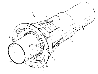
A fire protection sleeve is shown in Figure 1. It comprises an axially
extending tubular housing 2 formed of metal, at the left axially extending end
section 6 there is a connecting flange 3 which extends radially outwardly. The
-7-
CA 02325182 2000-11-07
connecting flange 3 is provided with connecting devices 4, such as boreholes
or
the like, which enable the fire-protection sleeve 1 to be fastened to a
concrete
form or to a wall. At the outside of the tubular housing 2, radially
projecting ribs 5
are provided, which prevent rotation of the fire-protection sleeve 1. At the
axially
extending end section 6 of the tubular housing, a closing part 7 is connected
detachably with the housing 2. For this purpose, locking brackets 8 project
radially outwardly from the periphery of the closing part 7, and engage
corresponding recesses in the connecting flange 3 and lock behind shoulders.
In
the axial end section 6 of the tubular housing 2, a heat-intumescing
composition
10 is provided. The heat-intumescing composition 10 is disposed at the inner
wall of the tubular housing 2 and surrounds an axially extending opening 9 of
the
tubular housing 2 in annular fashion. The diameter d of the opening 9, is
measured across the inner wall of the housing 2. In Figure 1, the right end
section of the tubular housing 2, opposite the connecting flange 3, is shown
closed off by a lid 14. Optionally the lid 14 is detachable, for example, if
the fire-
protection sleeve 1 is to be equipped with a pipe only in a later phase of the
building and if contamination of the opening 9 is to be prevented.
At the axially extending end section 6 of the tubular housing 2
accommodating the intumescing composition 10, axially flexible lamellas 12 are
disposed, which extend in the radially inward direction and project into the
opening 9 for a pipe, cable and the like.
_g_
CA 02325182 2000-11-07
Figure 2 shows an annular body 11 with a number of lamellas 12, which
are arranged in rosette fashion and project radially inward from the
circumference. The annular body 11 is formed of a spring steel. The lamellas
12 are constructed integrally with the annular body 11 and are flexible in the
axial
direction of the opening 9. For this purpose, the lamellas 12 are connected
over
a flector 13 with the circumference of the annular body 11. The wall thickness
of
the lamellas 12 is about 0.15 mm to about 0.4 mm. The lamellas 12 are at a
minimum distance from one another, which amounts to about 1 mm to about 8
mm. The lamellas 12 all have the same radially extending length and leave free
an opening cross-section with a diameter O, which amounts at least to about
10% of the diameter d of the axially extending opening 9 (Figure 1 ). The
annular
body 11 with the axially flexible lamellas 12 is mounted in the end section 6
of
the tubular housing 2 and is fixed by the closing part 7. It is in the
immediate
vicinity of the heat-intumescing composition 10, which is also disposed in the
end
section 6 of the housing 2 (Figure 1).
Figure 3 shows the inventive fire-protection sleeve 1 of Figure 1 with an
inserted pipe T, which may consist, for example, of plastics material. The
individual elements of the fire-protection sleeve 1 have the same reference
numerals as in Figure 1. The pipe T is pushed in from the side opposite the
end
section 6 of the housing 2. During this procedure, the flexible lamellas 12
are
bent corresponding to the diameter of the pipe T. The lamellas 12 press
against
the outer surface of the pipe T and center the latter within the fire-
protection
_g_
CA 02325182 2000-11-07
sleeve 1. In the event of a fire, the pipe T burns or melts away and the
intumescing composition 10, which is disposed at the inner wall of the end
section 6, expands. The expanded composition 10 penetrates through and is
deposited in the spaces between the lamellas 12. With this embedment, the
lamellas 12 form a reinforcement for the expanding intumescing composition 10,
which closes off the axial opening 9 of the housing 2.
-10-