Sélection de la langue

Search

Sommaire du brevet 2325418 

Énoncé de désistement de responsabilité concernant l'information provenant de tiers

Une partie des informations de ce site Web a été fournie par des sources externes. Le gouvernement du Canada n'assume aucune responsabilité concernant la précision, l'actualité ou la fiabilité des informations fournies par les sources externes. Les utilisateurs qui désirent employer cette information devraient consulter directement la source des informations. Le contenu fourni par les sources externes n'est pas assujetti aux exigences sur les langues officielles, la protection des renseignements personnels et l'accessibilité.

Disponibilité de l'Abrégé et des Revendications

L'apparition de différences dans le texte et l'image des Revendications et de l'Abrégé dépend du moment auquel le document est publié. Les textes des Revendications et de l'Abrégé sont affichés :

  • lorsque la demande peut être examinée par le public;
  • lorsque le brevet est émis (délivrance).
(12) Demande de brevet: (11) CA 2325418
(54) Titre français: TELEMETRE RADAR
(54) Titre anglais: RADAR RANGEFINDER
Statut: Réputée abandonnée et au-delà du délai pour le rétablissement - en attente de la réponse à l’avis de communication rejetée
Données bibliographiques
(51) Classification internationale des brevets (CIB):
  • G01S 07/40 (2006.01)
(72) Inventeurs :
  • KOLBLI, BERTRAM (Allemagne)
  • LOLKES, PETER (Allemagne)
  • KONIG, AXEL (Allemagne)
  • OHL, THEODOR (Allemagne)
(73) Titulaires :
  • HONEYWELL AG
(71) Demandeurs :
  • HONEYWELL AG (Allemagne)
(74) Agent: SMART & BIGGAR LP
(74) Co-agent:
(45) Délivré:
(86) Date de dépôt PCT: 1999-03-23
(87) Mise à la disponibilité du public: 1999-10-07
Licence disponible: S.O.
Cédé au domaine public: S.O.
(25) Langue des documents déposés: Anglais

Traité de coopération en matière de brevets (PCT): Oui
(86) Numéro de la demande PCT: PCT/EP1999/001979
(87) Numéro de publication internationale PCT: EP1999001979
(85) Entrée nationale: 2000-09-22

(30) Données de priorité de la demande:
Numéro de la demande Pays / territoire Date
198 13 631.5 (Allemagne) 1998-03-27

Abrégés

Abrégé français

L'invention concerne un télémètre radar présentant une antenne d'émission/réception (22) montée dans un boîtier à radome (12) sur une plate-forme (18) rotative, pour surveiller une zone à risque. Pour l'étalonnage, il est prévu un réflecteur à une distance connue. Ce réflecteur est formé par une antenne auxiliaire (24) à ligne de propagation (26) raccordée, dans le boîtier à radome (12). En fonction du rapport de démultiplication de la ligne de propagation utilisée, on obtient un écart virtuel d'importance correspondante du réflecteur.


Abrégé anglais


The inventive radar rangefinder has a transmitting/receiving antenna (22) for
surveying a danger area. Said antenna is located in a radome housing (12), on
a rotatable platform (18). A reflector is placed at a known distance in order
to calibrate the device. This reflector is formed by an auxiliary antenna (24)
with a connected delay line (26) inside the randome housing (12). The length
of the virtual distance of the reflector produced then corresponds to the
velocity factor of the delay line used.

Revendications

Note : Les revendications sont présentées dans la langue officielle dans laquelle elles ont été soumises.


Claim 1
1. A radar rangefinder having:
a transmitting/receiving antenna (22) arranged on
a rotating platform (18) for monitoring a danger
area,
a radome housing (12) for accommodating the
transmitting/receiving antenna (22), and a
reflector arranged at a known distance in order to
preset a calibration for the rangefinder, wherein
a) the reflector is provided by means of an
auxiliary antenna (24), which is likewise
arranged in the radome housing (12),
b) the auxiliary antenna (24) is connected to a
delay line (26), with the delay line (26) being
arranged together with the auxiliary antenna
(24) on the inner wall of the radome housing
(12),
c) the delay line (26) is short-circuited or
open-circuited (reflection factor = 1) at the end,
in order to use the shortening factor of the
delay line (26) to preset a virtual length
which is greater than the actual length of the
delay line.

-4-
Claims
2. The radar rangefinder as claimed in claim 1,
wherein the auxiliary antenna (24) is arranged in
an angle region outside the measurement range.
3. The radar rangefinder as claimed in claim 2,
wherein the auxiliary antenna is a horn antenna
(24).
4. The radar rangefinder as claimed in claim 2,
wherein the auxiliary antenna is a patch antenna.
5. The radar rangefinder as claimed in one of claims
1 to 4, wherein the transmitting/receiving antenna
(22) is moved to a position where it faces the
auxiliary antenna (24), for calibration.
6. The radar rangefinder as claimed in one of claims
1 to 4, wherein the calibration is carried out
during rotation of the transmitting/receiving
antenna (22).
7. The radar rangefinder as claimed in claim 1,
wherein the delay line (26) is arranged in a
winding in the dome (28) of the radome housing
(12).

-5-
8. The radar rangefinder as claimed in claim 7,
wherein the delay line (26) is provided by means
of a round waveguide with a short circuit or open
circuit (reflection factor = 1) at the end.
9. The radar rangefinder as claimed in claim 7,
wherein the delay line (26) is provided by means
of a rectangular waveguide with a short circuit or
open circuit (reflection factor = 1) at the end.

Description

Note : Les descriptions sont présentées dans la langue officielle dans laquelle elles ont été soumises.

_nr~
.,
CA 02325418 2000-09-22
~ WO 99/506'86 PCT/EP99/01979
Radar rangefinder
The present invention relates to a radar rangefinder as
claimed in the descriptive part of patent claim 1.
Such a radar rangefinder is used, for example, in an
arrangement for monitoring a danger area, as is
illustrated and described in DE 196 12 579 A1 from the
same applicant.
In the FMCw radar (frequency-modulated continuous-wave
radar) used there, temperature-dependent and age-
dependent changes normally prevent a desired strictly
linear frequency/time function. The voltage-controlled
oscillators in the available transmitters have non-
linear drive characteristics which are highly dependent
on temperature, load and the operating voltage.
In this context, it is known for calibration methods to
be used, which use a target which produces an echo at a
known distance. This allows self-calibration to be
carried out, using the Hilbert transformation. However,
the arrangement of a target which produces an echo at a
known distance has various disadvantages. Firstly, this
target can be concealed by people or objects moving in
the area. Secondly, raindrops, snow ~or ice in the
measurement path or on the radome housing in which the
radar rangefinder is arranged can adversely affect the
calibration. On the other hand, it is desirable for the
calibration distance to be as great as possible in
order to keep the calibration measurement error as
small as possible.
Against this background, the object of the present
invention is to specify a radar rangefinder having a
reflector for calibration, in which the disturbance
influences mentioned above are all precluded.

CA 02325418 2000-09-22
10
WO 99/50686 PCT/EP99/01979
- 2
This object is achieved according to the distinguishing
features of patent claim 1. Further advantageous
refinements of the radar rangefinder according to the
invention can be found in the dependent claims.
The invention will be described in more detail in the
following text with reference to an exemplary
embodiment which is illustrated in the figures of the
attached drawing, in which:
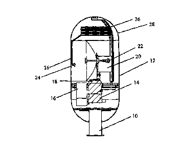
Figure 1 shows the principle of the design of the
radar rangefinder according to the
present invention; and
Figure 2 shows a block diagram of the components
used in the radar rangefinder shown in
Figure 1.
According to Figure 1, a fixed-position basic unit 14
with associated electronics 16 and a rotating platform
18 is arranged in a protective cover 12, which is
arranged on a base 10 and is referred to in the
following text as a radome housing, and the rotating
platform 18 is fitted with a radar
transmitting/receiving antenna 22 with associated
electronics 20. A horn antenna 24 is arranged inside
the radome housing 12 such that, when the
transmitting/receiving antenna 22 rotates through 360°,
the horn antenna 24 is painted in an angle region which
is located outside the danger area monitored by the
transmitting/receiving antenna 22. A patch antenna
could also be used instead of a horn antenna. The
transmitting/receiving antenna 22 may also be rotated
to a position where it faces the horn antenna 24, for
calibration. A delay line 26 is connected to the horn
antenna 24 and is short-circuited at its end, dictating
a specific shortening factor. Thus, for example, a
delay line 26 with a length of about 8 m corresponds to
an electrical length of 20 m, so that this results in

CA 02325418 2000-09-22
w
WO 99/50686 PCT/EP99/01979
- 3
conditions as if the target which produces the echo
were arranged at a distance of 20 m. The delay line 26
is routed upward into the dome 28 of the radome housing
12, where it is wound up in turns. The delay line 26
may be formed by a round waveguide or a rectangular
waveguide.
Figure 2 shows those components which are located
inside the radome housing 12 on the stationary base
unit 14 and the rotating platform 18.
The rotating platform 18 is driven by a motor 30, which
is driven by a control module 32 via a position
regulator 34 and a power output stage 36. A resolver 38
forms an actual value signal for the position regulator
34. A power supply~unit 40, which is connected to the
power supply via an EMC filter 42, supplies the
required regulated DC voltage. The voltage supply for
the rotating platform 18 as well as a communications
interface for incoming and outgoing data are provided
via a slipring arrangement 44.
The rotating platform 18 is fitted with the
transmitting/receiving antenna 22, an RF
transmitting/receiving module 46, which has a
preamplifier 48 and a voltage-controlled transceiver
50, as well as a digital signal processor module 52,
which comprises an A/D and D/A converter 54 and the
actual signal processor 56.
The danger area to be monitored is bounded by three
triple mirrors 58, 58' , 58", and a target object 60 is
to be detected in this area. The horn antenna 24 and
the delay line 26 are arranged on the inner wall inside
the radome housing 12.

Dessin représentatif
Une figure unique qui représente un dessin illustrant l'invention.
États administratifs

2024-08-01 : Dans le cadre de la transition vers les Brevets de nouvelle génération (BNG), la base de données sur les brevets canadiens (BDBC) contient désormais un Historique d'événement plus détaillé, qui reproduit le Journal des événements de notre nouvelle solution interne.

Veuillez noter que les événements débutant par « Inactive : » se réfèrent à des événements qui ne sont plus utilisés dans notre nouvelle solution interne.

Pour une meilleure compréhension de l'état de la demande ou brevet qui figure sur cette page, la rubrique Mise en garde , et les descriptions de Brevet , Historique d'événement , Taxes périodiques et Historique des paiements devraient être consultées.

Historique d'événement

Description Date
Demande non rétablie avant l'échéance 2005-03-23
Inactive : Morte - RE jamais faite 2005-03-23
Réputée abandonnée - omission de répondre à un avis sur les taxes pour le maintien en état 2005-03-23
Inactive : Abandon.-RE+surtaxe impayées-Corr envoyée 2004-03-23
Lettre envoyée 2001-01-16
Inactive : Correspondance - Transfert 2001-01-12
Inactive : Page couverture publiée 2001-01-05
Inactive : CIB en 1re position 2001-01-03
Inactive : Lettre de courtoisie - Preuve 2000-12-27
Inactive : Notice - Entrée phase nat. - Pas de RE 2000-12-20
Demande reçue - PCT 2000-12-15
Inactive : Transfert individuel 2000-11-30
Demande publiée (accessible au public) 1999-10-07

Historique d'abandonnement

Date d'abandonnement Raison Date de rétablissement
2005-03-23

Taxes périodiques

Le dernier paiement a été reçu le 2003-12-12

Avis : Si le paiement en totalité n'a pas été reçu au plus tard à la date indiquée, une taxe supplémentaire peut être imposée, soit une des taxes suivantes :

  • taxe de rétablissement ;
  • taxe pour paiement en souffrance ; ou
  • taxe additionnelle pour le renversement d'une péremption réputée.

Les taxes sur les brevets sont ajustées au 1er janvier de chaque année. Les montants ci-dessus sont les montants actuels s'ils sont reçus au plus tard le 31 décembre de l'année en cours.
Veuillez vous référer à la page web des taxes sur les brevets de l'OPIC pour voir tous les montants actuels des taxes.

Historique des taxes

Type de taxes Anniversaire Échéance Date payée
Taxe nationale de base - générale 2000-09-22
Enregistrement d'un document 2000-11-30
TM (demande, 2e anniv.) - générale 02 2001-03-23 2000-12-21
TM (demande, 3e anniv.) - générale 03 2002-03-25 2002-01-03
TM (demande, 4e anniv.) - générale 04 2003-03-24 2002-12-12
TM (demande, 5e anniv.) - générale 05 2004-03-23 2003-12-12
Titulaires au dossier

Les titulaires actuels et antérieures au dossier sont affichés en ordre alphabétique.

Titulaires actuels au dossier
HONEYWELL AG
Titulaires antérieures au dossier
AXEL KONIG
BERTRAM KOLBLI
PETER LOLKES
THEODOR OHL
Les propriétaires antérieurs qui ne figurent pas dans la liste des « Propriétaires au dossier » apparaîtront dans d'autres documents au dossier.
Documents

Pour visionner les fichiers sélectionnés, entrer le code reCAPTCHA :


Pour visualiser une image, cliquer sur un lien dans la colonne description du document. Pour télécharger l'image (les images), cliquer l'une ou plusieurs cases à cocher dans la première colonne et ensuite cliquer sur le bouton "Télécharger sélection en format PDF (archive Zip)" ou le bouton "Télécharger sélection (en un fichier PDF fusionné)".

Liste des documents de brevet publiés et non publiés sur la BDBC .

Si vous avez des difficultés à accéder au contenu, veuillez communiquer avec le Centre de services à la clientèle au 1-866-997-1936, ou envoyer un courriel au Centre de service à la clientèle de l'OPIC.


Description du
Document 
Date
(aaaa-mm-jj) 
Nombre de pages   Taille de l'image (Ko) 
Dessin représentatif 2001-01-04 1 8
Abrégé 2000-09-21 1 63
Description 2000-09-21 3 130
Revendications 2000-09-21 3 78
Dessins 2000-09-21 2 61
Rappel de taxe de maintien due 2000-12-18 1 112
Avis d'entree dans la phase nationale 2000-12-19 1 195
Courtoisie - Certificat d'enregistrement (document(s) connexe(s)) 2001-01-15 1 113
Rappel - requête d'examen 2003-11-24 1 123
Courtoisie - Lettre d'abandon (requête d'examen) 2004-05-31 1 167
Courtoisie - Lettre d'abandon (taxe de maintien en état) 2005-05-17 1 174
Correspondance 2000-12-19 1 14
PCT 2000-09-21 14 491