Note : Les descriptions sont présentées dans la langue officielle dans laquelle elles ont été soumises.
CA 02326169 2007-01-16
23940-1199
INHALATION DEVICE WTTH A DOSE COUNTING UNIT
The present invention relates to an inhaler for administering medicament by
inhalation, in
particular a powder inhaler for administering powder containing medicament.
A number of powder inhalers are known which use different systems for
introducing a dose
of powder containing medicament into an air stream. Typically, the powder is
inhaled into
the lungs of a patient in order to treat, for example, asthma.
EP-A-0237507 discloses one such powder inhaler. This inhaler comprises an
inhalation
channel and a mouthpiece which. includes an air chamber and an outlet nozzle,
which
inhalation channel and mouthpiece together define a flow path through which a
stream of
air is drawn during inhalation by a user. This inhaler further comprises a
dosing
mechanism for providing a dose of powder to the inhalation channel. During
inhalation,
is air is first drawn into and through the inhalation channel so as to pick up
powder. The
stream of air containing powder is then drawn through the air chamber and out
of the outlet
nozzle of the mouthpiece. This inhaler still further comprises an indicating
wheel which
includes marking on the periphery thereof for providing an indication as to
the usage of the
inhaler.
Although the above-described known powder inhaler functions quite adequately,
it is an
aim of the present invention to provide a powder inhaler which includes an
electronic dose
counter for providing the user with a precise indication of either the number
of doses used or
the number of doses remaining.
CA 02326169 2007-01-16
23940-1199
la
Accordingly, in one aspect of the present
invention, there is provided an inhaler for administering
medicament by inhalation, comprising: an inhalation channel;
a rotatable dosing unit which includes at least one dosing
element for providing a dose of medicament to the inhalation
channel; and a dose counting unit which comprises an
electronic display, an electrical circuit for counting each
dose of medicament provided to the inhalation channel and
driving the display so as to provide an indication as to the
usage of the inhaler, the electrical circuit including at
least one switch which comprises a contact element moveable
between a first open position and a second closed position
when a dose of medicament is provided to the inhalation
channel, and a rotatable member connected to the dosing unit
so as to be rotatable therewith, the rotatable member
including at least one cam surface which includes at least
one cam, each cam on each cam surface being configured, on
rotation of the dosing unit to provide a dose of medicament
to the inhalation channel, such as to cause movement of the
contact element of the respective at least one switch
between the first open position and the second closed
position.
In another aspect, there is provided an inhaler
for administering medicament by inhalation, comprising: an
inhalation channel; a rotatable dosing unit which includes
at least one dosing element for providing a dose of
medicament to the inhalation channel; and a dose counting
unit which comprises an electronic display, an electrical
circuit for counting each dose of medicament provided to the
inhalation channel and driving the display so as to
CA 02326169 2000-09-26
WO 9999920 PCT/SE99/00540
2
provide an indication as to the usage of the inhaler, the electrical circuit
including at least one
switch which comprises a contact element and is one of opened or closed when a
dose of
medicament is provided to the inhalation channel, and a rotatable member
connected to the
dosing unit so as to be rotatable therewith, the rotatable member including at
least one cam
s surface which includes at least one cam, each cam on each cam surface being
configured, on
rotation of the dosing unit to provide a dose of medicament to the inhalation
channel, such as
to cause movement of the contact element of the respective at least one switch
and one of
open or close the same.
Preferably, the electrical circuit includes a first switch which comprises a
first contact
element and a second switch which comprises a second contact element and the
rotatable
member includes first and second cam surfaces which each include at least one
cam which is
configured to cause movement of a respective one of the first and second
contact elements so
as to one of open or close the first and second switches.
Preferably, the dosing unit includes a plurality of dosing elements and each
cam surface
includes a plurality of cams having the same angular spacing as the dosing
elements in the
dosing unit.
More preferably, the plurality of dosing elements in the dosing unit and the
plurality of cams
on each cam stirface are angularly equi-spaced.
Preferably, the corresponding cams on the first and second cam surfaces are
rotationally
offset in relation to one another such that one of the first and second
switches is one of
2i opened or closed before the other.
More preferably, the cams on the first and second cam surfaces are
rotationally offset such
that, on rotation of the rotatable member, in a first phase of rotation one of
the first and
second switches is closed and the other of the first and second switches is
open, in a second
phase of rotation the first and second switches are closed, in a third phase
of rotation the one
CA 02326169 2000-09-26
WO 99/49920 PCT/SE99/00540
3
of the first and second switches is open and the other of the first and second
switches is
closed and in a fourth phase of rotation the first and second switches are
open, and the
electrical circuit is configured to count only when this sequence of closing
and opening the
first and second switches is followed.
Preferably, each contact element is a resiliently-biased arm which includes a
first part which
rides on the respective cam surface and a second part which provides a contact
pad.
More preferably, the arm is resilient and configured such that the second part
thereof which
iu provides a contact pad moves at least partly laterally over a contact
surface when the first part
thereof rides onto and over a cam.
More preferably, the arm includes a bend, the outer surface of which provides
the second part
thereof that rides on the respective cam surface.
Preferably, the dosing unit includes a shaft which includes a surface provided
with one of at
least one of an external or internal spline and the rotatable member includes
a surface
provided with the other of at least one of an external or internal spline, the
splines being
engaged such that the dosing unit and the rotatable member in use rotate
concomitantly.
In one embodiment the electrical circuit is configured to drive the display to
display the
number of doses used.
In another embodiment the electrical circuit is configured to drive the
display to display the
number of doses remaining.
Preferably, the electrical circuit is configured to drive the display to
display intermittently the
number of doses remaining when a predetermined number of doses or less are
remaining.
Preferably, the display is a liquid crystal display.
CA 02326169 2000-09-26
WO 99/49920 PCT/SE99/00540
4
Preferably, the inhaler further comprises a rotatable grip portion which is in
use gripped by a
user and when rotated in one sense rotates the dosing unit to provide a dose
of medicament to
the inhalation channel.
By virtue of the present invention the user is provided by an accurate and
reliable indication
as to the usage of the inhaler.
The powder inhaler of the present invention may be used with any suitable form
of powder,
io including powders introduced into the air stream in the raw state or as
conglomerate,
micronised or ordered mixture particles. Furthermore, the active ingredient or
ingredients of
the powder may be diluted with one or more substances such as lactose and may
include
substances for the treatment of various conditions, not necessarily
respiratory conditions.
Indeed, the powder can include genetic material and need not be restricted to
human use only.
Medicaments suitable for administration by the powder inhaler of the present
invention are
any which may be delivered by inhalation and include, for example, 02-
adrenoreceptor
agonists, for example, salbutamol, terbutaline, rimiterol, fenoterol,
reproterol. adrenaline,
pirbuterol, isoprenaline, orciprenaline, bitolterol, salmeterol, formoterol,
clenbuterol,
procaterol, broxaterol, picumeterol, TA-2005, mabuterol and the like, and
their
pharmacologically acceptable esters and salts; anticholinergic
bronchodilators, for
example, ipratropium bromide and the like; glucocorticosteroids, for example,
beclomethasone, fluticasone, budesonide, tipredane, dexamethasone,
betamethasone,
fluocinolone, triamcinolone acetonide, mometasone and the like, and their
2i pharmacologically acceptable esters and salts; antiallergic medicaments,
for example,
sodium cromoglycate and nedocromil sodium; expectorants; mucolytics;
antihistamines;
cyclooxygenase inhibitors; leukotriene synthesis inhibitors; leukotriene
antagonists;
phospholipase-A2 (PLA2) inhibitors; platelet aggregating factor (PAF)
antagonists and
CA 02326169 2000-09-26
WO 99/49920 PCT/SE99/00540
prophylactics of asthma; antiarrhythmic medicaments; tranquilisers; cardiac
glycosides;
hormones; antihypertensive medicaments; antidiabetic medicaments;
antiparasitic
medicaments; anticancer medicaments; sedatives; analgesic medicaments;
antibiotics;
antirheumatic medicaments; immunotherapies; antifungal medicaments;
antihypotension
; medicaments; vaccines; antiviral medicaments; proteins; polypeptides and
peptides, for
example, peptide hormones and growth factors; polypeptide vaccines; enzymes;
endorphines; lipoproteins and polypeptides involved in the blood coagulation
cascade;
vitamins; and others, for example, cell surface receptor blockers,
antioxidants, free radical
scavengers and organic salts of N,N'-diacetylcystine.
A preferred embodiment of the present invention will now be described
hereinbelow by way
of example only with reference to the accompanying drawings, in which:
Figure 1 illustrates a perspective view of a powder inhaler in accordance with
a preferred
embodiment of the present invention;
Figure 2(a) illustrates a part exploded perspective view of the inhaler of
Figure 1;
Figure 2(b) illustrates a vertical sectional view (along section I-I in Figure
2(a)) of the
mouthpiece of the inhaler of Figure 1;
Figure 3 illustrates an exploded perspective view of the component parts
disposed within the
inhaler body of the inhaler of Figure 1;
Figures 4(a) and (b) illustrate respectively side and plan views of the dosing
unit of the
inhaler of Figure 1;
Figure 4(c) illustrates a vertical sectional view (along section II-II in
Figure 4(a)) of the
dosing unit of Figures 4(a) and (b);
CA 02326169 2000-09-26
WO 99/49920 PCT/SE99/00540
6
Figure 4(d) illustrates in enlarged scale a fragmentary plan view of the
dosing unit of Figures
4(a) and (b);
; Figures 5(a) to (e) illustrate respectively front, rear, side, plan and
underneath plan views of
the body part of the dose counting unit of the inhaler of Figure 1;
Figure 5(f) illustrates a vertical sectional view (along section III-III in
Figure 5(a)) of the body
part of Figures 5(a) to (e);
io
Figure 5(g) illustrates a horizontal sectional view (along section IV-IV in
Figure 5(b)) of the
body part of Figures 5(a) to (e);
Figures 6(a) to (d) illustrate respectively one side, other side, plan and
underneath plan views
15 of the rotor of the dose counting unit of the inhaler of Figure 1;
Figure 6(e) illustrates a vertical sectional view (along section V-V in Figure
6(a)) of the rotor
of Figures 6(a) to (d);
20 Figures 7(a) to (c) illustrate respectively end, side and plan views of the
first conductive
member of the electrical device of the inhaler of Figure 1;
Figures 8(a) to (c) illustrate respectively rear, side and plan views of the
second conductive
member of the electrical device of the inhaler of Figure 1;
Figures 9(a) to (c) illustrate respectively front, one side and other side
views of the dose
counting unit of the inhaler of Figure 1;
Figure 9(d) illustrates a horizontal sectional view (along section VI-VI in
Figure 9(a)) of the
dose counting unit of Figures 9(a) to (c);
CA 02326169 2000-09-26
WO 99/49920 PCT/SE99/00540
7
Figure 9(e) illustrates a horizontal sectional view (along section VII-VII in
Figure 9(a)) of the
dose counting unit of Figures 9(a) to (c);
Figure 9(f) illustrates a horizontal sectional view (along section VIII-VIII
in Figure 9(a)) of
the dose counting unit of Figures 9(a) to (c);
Figure 10(a) illustrates a side view of the inhaler body of the inhaler of
Figure 1. with the
internal component parts disposed therein;
Figure 10(b) illustrates a vertical sectional view (along section IX-IX in
Figure 10(a)) of the
inhaler body of Figure 10(a);
Figure 10(c) illustrates a horizontal sectional view (along section X-X in
Figure 10(a)) of the
i s inhaler body of Figure 10(a);
Figure 10(d) illustrates a horizontal sectional view (along section XI-XI in
Figure 10(a)) of
the inhaler body of Figure 10(a);
Figure l0(e) illustrates a horizontal sectional view (along section XII-XII in
Figure 10(a)) of
the inhaler body of Figure 10(a); and
Figure 10(f) illustrates a horizontal sectional view (along section XIII-XIII
in Figure 10(a)) of
the inhaler body of Figure 10(a).
The inhaler comprises a mouthpiece 2, an inhaler body 3 and a rotatable grip
portion 4 for
operating a dosing mechanism for providing doses of powder for inhalation.
The inhaler body 3 comprises a generally cylindrical tubular member 5 which is
capped by
a divider 6. which in this embodiment are integrally formed. For aesthetic
reasons the
CA 02326169 2000-09-26
WO 99/49920 PCT/SE99/00540
8
inhaler body 3 is an opaque moulding. The tubular member 5 includes a first
opening 7
which acts as a supplementary air inlet and a second opening 8 through which
an electronic
display 57 is visible for providing an indication as to the usage of the
inhaler. The divider
6 includes a first opening 9 which is in communication with the first opening
7 in the
tubular member 5 and acts as a supplementary air inlet and second and third
openings 10,
11 into which extend an inhalation channe124 and a storage chamber 28 as will
be
described in more detail hereinbelow.
Within the inhaler body 3 are housed the component parts of the dosing
mechanism. These
component parts include a dosing unit 16 which comprises a member 17 having a
planar
upper surface in which a plurality of dosing elements 18 are provided and a
shaft 20 which
extends axially from the centre of the member 17, an inhalation unit 22 which
comprises an
inhalation channe124 and a storage unit 26 which comprises a storage chamber
28 for
storing powder. The above-mentioned component parts of the dosing mechanism
are
1s assembled by passing the inhalation channe124 through an opening 30 in the
storage unit
26 and passing the shaft 20 through central openings 32, 34 in the inhalation
unit 22 and
the storage unit 26 respectively. When so assembled, the upper ends of the
inhalation
channel 24 and the storage chamber 28 pass respectively through the second and
third
openings 10, 11 in the divider 6. In this way, the inhalation unit 22 and the
storage unit 26
are fixed in position in relation to one another and the dosing unit 16 can be
rotated relative
thereto.
The dosing unit 16 comprises a plurality of dosing elements 18, each in the
fotm of a
plurality of through holes, which are equi-spaced circularly about the central
shaft 20. In
this embodiment the dosing unit 16 includes five dosing elements 18 which are
angularly
spaced apart from one another by an angle of 72 degrees. The dosing unit 16
further
comprises a plurality of wedge-shaped elements 36, in the same number and
spacing as the
dosing elements 18, disposed around the outer periphery of the member 17. Each
wedge-
shaped element 36 has a first, axially-directed surface 36a which faces in one
sense, in this
embodiment in the clockwise sense when viewed from above, and a second surface
36b
CA 02326169 2000-09-26
WO 9999920 PCT/SE99/00540
9
which has a component which faces in the opposite, counter-clockwise sense. In
use. the
dosing unit 16 is rotated by rotating the grip portion 4 in the opposite
sense, that is, the
counter-clockwise sense when viewed from above, the grip portion 4 including a
resilient
member (not illustrated) which is configured to engage with the axially-
directed surface
> 36a of a respective one of the wedge-shaped elements 36 so as to rotate the
dosing unit 16
between first and second angularly-spaced positions, in this embodiment
positions
angularly spaced 72 degrees apart, by pushing the respective wedge-shaped
element 36.
On rotation of the grip portion 4 in the one, clockwise sense between the
second and the
first angularly-spaced positions, the dosing unit 16 remains stationary and
the resilient
io member is located behind the axially-directed surface 36a of the adjacent
wedge-shaped
element 36; the resilient member riding over the second surface 36b of the
adjacent wedge-
shaped element 36. Further, in this embodiment, the central shaft 20 comprises
a first,
lower part 20a, the outer surface of which is generally cylindrical and acts
as a bearing
surface in the central openings 32, 34 in the inhalation unit 22 and the
storage unit 26, and
is a second, upper part 20b which is of smaller radial dimension than the
first part 20a and
includes a plurality of external splines 38 on the outer surface thereof.
In this embodiment the storage unit 28 is open at the bottom such that in use
powder is
provided to the dosing unit 16 under the action of gravity and the inhalation
unit 22 further
20 comprises scrapers 40 which are resiliently biased against the upper
surface of the member
17 in which the dosing elements 18 are provided. In this way, as the dosing
unit 16 is
rotated, the dosing elements 18 are filled with powder by the scrapers 40.
Powder is
prevented from passing through the dosing elements 18 by a plate (not
illustrated) which is
disposed beneath the dosing unit 16.
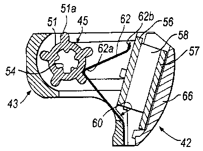
Within the inhaler body 3 is also housed a dose counting unit 42 for counting
the number
of operations of the grip portion 4 in providing doses of powder to the
inhalation channel
24. The dose counting unit 42 is located on the storage unit 26 between the
storage
member 28 thereof and the inhalation channe124.
CA 02326169 2000-09-26
WO 99/49920 PCT/SE99/00540
The dose counting unit 42 comprises a body part 43 which includes a first
cavity 44 and a
rotor 45 which is disposed in the first cavity 44. The rotor 45 comprises a
hollow shaft 46
which includes first and second bearing surfaces 47, 48 at opposed ends
thereof, which first
and second bearing surfaces 47, 48 are configured to fit respectively within
lower and
5 upper recesses 49, 50 in opposed surfaces of the first cavity 44. The first
bearing surface
47 and the lower recess 49 are of different, in this embodiment larger,
dimension than the
second bearing surface 48 and the upper recess 50 so as to ensure that the
rotor 45 is fitted
in the first cavity 44 with the correct orientation. The outer surface of the
shaft 46 includes
first and second axially-spaced cam surfaces 51, 52, each including a
plurality of cams 51 a.
10 52a of the same number. The cams 51a, 52a on the first and second cam
surfaces 51. 52
have rounded distal ends and are circumferentially equi-spaced. In this
embodiment each
cam surface 51, 52 includes five cams 51a, 52a which are angularly spaced
apart from one
another by an angle of 72 degrees, with the corresponding cams 51 a, 52a on
the first and
second cam surfaces 51, 52 being angularly shifted by a predetermined angle,
typically
is about 18 degrees, such that the cams 51 a on the first cam surface 51 are
forward of the
corresponding cams 52a on the second cam surface 52 in the sense of rotation,
in this
embodiment in the counter-clockwise sense when viewed from above. The inner
surface
of the shaft 46 includes a plurality of internal splines 54 which are
configured to receive the
external splines 38 on the upper part 20b of the shaft 20 of the dosing unit
16 so as
rotationally to fix the rotor 45 relative to the dosing unit 16, whereby the
rotor 45 is rotated
concomitantly with the dosing unit 16. In this embodiment the splines 38, 54
are not a
tight fit but rather have a limited freedom of movement so as to allow for
relatively easy
inter-engagement thereof. In rotationally fixing the dosing unit 16 and the
rotor 45 using
splines 38, 54, as compared, for example, to forming the dosing unit 16
integrally with the
rotor 45, a certain degree of tolerance is provided since the position of the
rotor 45 which
includes the cam surfaces 51, 52 is not dependent upon the position of the
dosing unit 16.
The dose counting unit 42 further comprises an electrical device 55 which
comprises a
printed circuit board 56 which is mounted to the body part 43, the printed
circuit board 56
includina an integrated circuit for counting input pulses corresponding to the
number of
CA 02326169 2000-09-26
WO 99/49920 PCT/SE99/00540
Il
operations of the grip portion 4 in providing doses of powder to the
inhalation channel 24
and driving an electronic display 57, an electronic display 57, in this
embodiment a liquid
crystal display, for displaying either the number of doses provided to the
inhalation channel
24 or the number of doses remaining in the storage chamber 28 which is
connected to one
side 56a of the printed circuit board 56 by first and second elastomeric
conducting elements
58 (so-called zebra strips) and a first conductive member 59 connected to the
other side
56b of the printed circuit board 56. The first conductive member 59 is a gold-
plated
element and comprises a resilient arm 59a which is configured to contact one
of the
terminals, in this embodiment the anode terminal, of a battery cell 64. The
electrical
device 55 further comprises a second conductive member 60 which is mounted to
the body
part 43. The second conductive member 60 is a gold-plated element and
comprises a first
resilient arm 61 which is configured to contact the other of the terminals, in
this
embodiment the cathode terminal, of a battery cell 64 and includes a contact
pad 61 a which
contacts the respective terminal on the printed circuit board 56, a second
resilient arm 62
which acts as a first switch element and a third resilient arm 63 which acts
as a second
switch element. The second and third arms 62, 63 are identical in shape and
include a bend
62a, 63a which encloses an acute angle, in this embodiment of about 72
degrees, with the
bend 62a. 63a defining a knee which is acted upon by a respective one of the
first and
second cam surfaces 51, 52 of the rotor 45 as will be described in detail
hereinbelow. The
distal ends of the second and third arms 62, 63 each include contact pads 62b,
63b for
contacting a respective contact on the printed circuit board 56 for making
first and second
switches.
The dose counting unit 42 yet further comprises a battery cell 64 which is
disposed in a
~; second cavity 65 in the body part 43. The battery cell 64 is arranged such
that the anode
and cathode terminals thereof contact respectively the arm 59a of the first
conductive
member 59 and the first arm 61 of the second conductive member 60.
The dose counting unit 42 still further comprises a window 66, in this
embodiment formed
of a transparent plastics material, which is fixed to the body part 43,
preferably by clipping.
CA 02326169 2000-09-26
WO 99/49920 PCT/SE99/00540
12
The window 66 fills the second opening 8 in the tubular member 5 of the
inhaler body 3 so
as to protect the electronic display 57 therebehind.
As illustrated in Figures l and 2(a), the mouthpiece 2 is fixed to the divider
6. The
mouthpiece 2 comprises first and second parts 67, 68, the first part 67 being
the part which
is gripped in the lips of a user and includes an outlet opening 69 through
which air
containing powder is in use drawn on inhalation by a user and the second part
68 being an
insert fitted within the first part 67. The second part 68 comprises a tubular
section 70
which includes one or more spirally or helically shaped projections 71 that
act to deflect
the air drawn therethrough and thereby deagglomerate any larger particles of
entrained
powder and a substantially radially-directed flange 72 which defines the upper
surface of
an air chamber that is in fluid communication with the inhalation channel 24
through which
air containing powder is drawn on inhalation by a user.
The inhaler further comprises a cover plate 74 which is located above the
divider 6. The
cover plate 74 includes first and second openings 75, 76 which correspond
respectively to the
inhalation channel 24 and the supplementary air inlet 9. The cover plate 74
further comprises
a powder dislodging member 78 which is configured to contact a part of the
lower surface of
the flange 72 which defines the upper surface of the air chamber. In this
embodiment the
powder dislodging member 78 is integrally formed with the cover plate 74 and
comprises an
arm which is formed of resilient material and biased towards the lower surface
of the flange
72. In use, on rotating the mouthpiece 2 relative to the inhaler body 3, the
lower surface of
the flange 72 is rotated relative to the powder dislodging member 78, thereby
causing powder
which may have accumulated on that part of the lower surface of the flange 72
immediately
upstream of the powder dislodging member 78 in a rotational sense to be
removed.
In use, as described hereinabove, powder is transferred from the storage
chamber 28 to one
of the dosing elements 18, and, with rotation of the dosing unit 16, the one
dosing element
18 provides a dose of powder to the inhalation channel 24. The dosing unit 16
is rotated by
rotating the grip portion 4 in the counter-clockwise sense when viewed from
above
CA 02326169 2000-09-26
WO 99/49920 PCT/SE99/00540
13
between first and second angularly-spaced positions. Initially, prior to first
use of the
inhaler, the display 57 displays a flashing symbol, typically a minus sign,
and the user is
required to operate the grip portion 4 a predetermined number of times,
typically three or
four times, so as to prime the dosing elements 18 in the dosing unit 16. When
so primed,
s the display 57, which in this embodiment displays the number of doses
remaining, displays
an initial value which corresponds to the number of doses of powder stored in
the storage
chamber 28. In this state the inhaler is ready for use and subsequently after
each operation
of the grip portion 4 the display 57 decrements by one. Further, as a warning
to the user,
the value displayed on the display 57 flashes when a predetermined number of
doses of
powder, typically 20 doses, or less are remaining. It will, of course, be
understood that in
an alternative embodiment the display 57 could initially, after priming of the
inhaler,
display zero and thereafter display the number of times the grip portion 4 is
operated.
On rotating the grip portion 4 between the first and second angularly-spaced
positions the
is dosing unit 16 and the rotor 45 which is rotationally fixed thereto are
rotated through the
same angle, in this embodiment an angle of 72 degrees. In a first phase of
this angular
rotation of the rotor 45, the bend 62a in the second arm 62 of the second
conductive
member 60 which rides on the first cam surface 51 of the rotor 45 rides up
onto one of the
cams 51 a on that cam surface 51 causing the bend 62a and hence the distal end
of the
second arm 62 to be deflected outwardly such that the contact pad 62b thereof
contacts a
contact on the printed circuit board 56 so as to make a first switch. Whilst
making contact
with the contact on the printed circuit board 56, the contact pad 62b moves
laterally
thereover so as to ensure a good contact, even if, for example, powder had
deposited on the
contact. In a second phase of this angular rotation of the rotor 45, with the
bend 62a in the
second arm 62 of the second conductive member 60 on the one of the cams 51 a
on the first
cam surface 51 and the contact pad 62b contacting the one contact on the
printed circuit
board 56, the bend 63a in the third arm 63 of the second conductive member 60
which
rides on the second cam surface 52 of the rotor 45 rides up onto the
corresponding one of
the cams 52a on that cam surface 52 causing the bend 63a and hence the distal
end of the
third arm 63 to be deflected outwardly such that the contact pad 63b thereof
contacts
CA 02326169 2000-09-26
WO 99/49920 PCT/SE99/00540
14
another contact on the printed circuit board 56 so as to make a second switch.
Similarly to
the contact pad 62b of the second arm 62, whilst making contact with the
respective
contact on the printed circuit board 56, the contact pad 63b of the third arm
63 moves
laterally thereover so as to ensure a good contact. In a third phase of this
rotation of the
i rotor 45, with the bend 63a in the third arm 63 of the second conductive
member 60 on the
one of the cams 52a on the second cam surface 52 and the contact pad 63b
contacting the
other contact on the printed circuit board 56, the bend 62a in the second arm
62 of the
second conductive member 60 rides off the one of the cams 51 a on the first
cam surface 51
whereby the bend 62a and hence the distal end of the second arm 62 move
inwardly such
that the contact pad 62b thereof no longer contacts the one contact on the
printed circuit
board 56 so as to open the first switch. In a fourth phase of this rotation of
the rotor 45, the
bend 63a in the third arm 63 of the second conductive member 60 rides off the
one of the
cams 52a on the second cam surface 52 whereby the bend 63a and hence the
distal end of
the third arm 63 move inwardly such that the contact pad 63b thereof no longer
contacts the
other contact on the printed circuit board 56 so as to open the second switch.
In this way,
on rotating the grip portion 4 of the inhaler to provide a dose of powder to
the inhalation
channel 24, the switches provided by the second and third arms 62, 63 of the
second
conductive member 60 follow the sequence open-open, closed-open, closed-
closed, open-
closed and open-open. In this embodiment the electrical device 55 is
configured to count
only when the above sequence is followed.
In providing the electrical device 55 of the dose counting unit 42 with two
switches which
have to be closed in order for the operation of the grip portion 4 to be
counted, the dose
counting circuit is more reliable than if the electrical device 55 were to
include only one
switch since there is a much reduced risk of two switches as opposed to one
switch being
inadvertently made to record a count if the inhaler were subjected to a sudden
shock, for
example, as when dropped onto a hard surface. Further, by configuring the dose
counting
circuit only to count when the switches follow the above-mentioned sequence,
it is possible
to ensure that the dose counting circuit does not erroneously count as may
happen if the
dose counting circuit were configured to count merely when both switches were
CA 02326169 2000-09-26
WO 99/49920 PCT/SE99/00540
- 15
simultaneously made, which, although unlikely, could possibly occur if the
inhaler were to
experience a sudden shock, for example, as when dropped onto a hard surface.
Finally, it will be understood that the present invention has been described
in its preferred
embodiment and can be modified in many different ways without departing from
the scope of
the appended claims.