Note : Les descriptions sont présentées dans la langue officielle dans laquelle elles ont été soumises.
CA 02326269 2000-11-17
METHOD AND DEVICE FOR CONTACTLESS ONLINE MEASURING
OF THE WALL THICKNESS OF HOT-ROLLED PIPES
NACKGROU1~ OF THE ~NYENTION
1. Field of the Invention
The invention relates to a method and a device for
contactless online measuring of the wall thickness of hot
pipes for detecting undesirable inner wall structures such
as inner polygons etc. of hot-rolled, in particular,
stretch-reduced pipes.
2. Description of the Related Art
In the manufacture of seamless and welded steel pipes
it is conventional to employ the so-called stretch reduction
method in order to produce in a very flexible way, based on
a few semi-finished product dimensions, a plurality of
diameters and wall thicknesses of finished pipe sizes. The
advantage of this method, which does not require inner
tools, resides in the quick and inexpensive variation of the
wall thickness and the diameter.
The deformation of the pipe blank is carried out in a
. plurality of sequentially arranged roll stands wherein by
speed variations in the individual stands a defined tension
between the roll stands is produced and thus the wall
1
CA 02326269 2000-11-17
thickness of the finished pipe can be adjusted in a directed
way. The shaping within the stretch reduction rolling mill
is nowadays carried out generally in three-roll or four-roll
stands whose pass is not circular but oval on three or four
sides. This form of the pass is generally unavoidable, and
only the last pass of such roll stands is generally circular
because the finish-rolled pipe should be substantially of a
round and circular shape.
As a result of the oval pass there are often distinct
irregularities in the cross-sectional wall thickness of the
stretch-reduced pipe. These irregularities of the wall
thickness have different shapes. For example, for a three-
roll stand they have a hexagonal shape and are referred to
as inner polygon. In a four roll stand the shape is
octagonal. Like all other deviations of the wall thickness,
the inner polygon formation also means a quality loss.
Since the inner polygon formation is the function of
the wall thickness or, in more precise terms, of the ratio
wall thickness to pipe diameter, it is actually necessary to
provide different passes for the rolls, i.e., different oval
- appearances of the roll pass, for producing a large wall
thickness range. However, since the making available of
roll stands requires a considerable expenditure, in general,
2
CA 02326269 2000-11-17
only two different passes are used, one round pass with
minimal oval appearance of the pass opening for thick-walled
pipes as well as one oval pass with large oval appearance of
the pass opening for thin-walled pipes. Otherwise, it is
attempted to keep the occurring inner hexagon formation as
small as possible by adjusting the average tension stress or
the "tension" in the rolling stock during deformation
optimally. This is so because it was found by
experimentation that the degree of polygon formation changes
as a function of tension. Once this tension optimization
has been carried out laboriously, it is still not possible
to obtain at all times pipes with minimal inner polygon
because momentary unavoidable changes of the influencing
parameters occur, i.e., an inner polygon formation as a
result of momentarily changing deformation conditions as
well as a considerable expenditure had to be accepted in
order to perform an optimization prior to production.
Seamless steel pipes are conventionally produced in
three deformation steps including hole punching in a cross-
rolling mill, stretching in an "Assel" rolling mill, a
continuum rolling mill or other rolling mills, and finish-
- rolling in a stretch-reduction rolling mill. All three
deformation steps cause the pipe wall to have
characteristic, undesirable deviations from the nominal
3
CA 02326269 2000-11-17
dimensions which are overlaid by each successive deformation
step and in this overlaid form are found in the wall of the
stretch-reduced pipe. For example, in a two-roll cross-
rolling mill, two thickened wall portions are formed which
extend spirally about the pipe which, in a cross-section of
the pipe, are expressed as a circumferential eccentric
shape. When the second deformation step is carried out on
an "Assel" rolling mill, it is also possible that spirally
extending thickened wall portions result which extend either
in the same direction but with different pitch about the
pipe or have an oppositely arranged rotational direction and
may cross the spirals of the cross-rolling mill.
On the other hand, in the case of a stretch-reduced
pipe which has been pre-rolled in a continuum rolling mill,
a quadrangle formation can occur in addition to the inner
polygon of SRR (stretch reduction rolling) and the
circumferential eccentric shape of the cross-rolling
process. This quadrangle formation can be detected with
respect to its phase position at the SRR exit so that a
precondition is provided for counteracting these inner
disturbances.
The problem of the undesirable wall structures
occurring in pipes could be solved if it were possible
4
CA 02326269 2000-11-17
during the production process to perform a correction of the
inner flaw formation by means of the control circuit, for
example, by variation of the tension parameters (change of
the speed series). Since, as is known in the art, between
the parameter of tension distribution and the inner polygon
formation a definite correlation exists, the inner polygon
formation could be automatically reduced without affecting
the wall thickness of the semi-finished pipe. However, this
requires that the course of the inner polygon formation and
of the overlaying errors is known, for example, by
contactless measuring of the wall thickness of the hot-
rolled pipes directly after rolling when they exit the
rolling mill with a constant center of the pipe. However,
this requires an economical measuring method and a cost-
effective measuring device which, in addition to measuring
the wall thickness course across the length of the pipe or
via the time for passing through, provides important
information in regard to the inner polygon formations
occurring during stretch reduction.
CA 02326269 2000-11-17
SU1~RY OF THE INVENTION
It is an object of the present invention to provide a
method and a device for contactless online wall thickness
measurement of the hot-rolled pipe with which the
undesirable wall structures such as inner polygons,
eccentric shapes, or quadrangles can be detected with
minimal measuring-technological expenditure in order to be
able to carry out measures for quality improvement at an
early point in time of the manufacturing process.
In accordance with the present invention, this is
achieved in that, with the aid of the laser ultrasound
method and by using at least one measuring head, a segment
of the wall of the pipe to be measured, during or directly
after the rolling process, is scanned in the circumferential
direction and, optionally by mathematical analyses and
symmetry considerations, the course of the wall of the pipe
cross-section is reconstructed in a computer wherein, when
using several measuring heads pivotable in the
circumferential direction, each measuring head sweeps across
a different correlated portion of the pipe wall.
With the laser ultrasound wall thickness measuring
method the classic principle of ultrasound propagation time
6
CA 02326269 2000-11-17
measurement is used. Based on the time of the ultrasound
pulse (twice) passing through the pipe wall, the desired
wall thickness will result based on the known speed of
sound. Since the coupling of the ultrasound in the
thickness measurement of hot walls with temperatures in the
range of 1f00 °C must be carried out in a contactless way at
the excitation as well as the detection side, this is
realized by optical methods in which the measuring head
itself can remain at a thermally safe spacing from the
rolling stock to be measured, High energy light pulses in
the infrared range, generated by a flashlamp-pumped laser
which is directed onto the rolling stock to be measured, are
absorbed in the pipe surface and this results partially in
an evaporation of extremely thin surface layers. As a
result of the evaporation pulse, based on pulse
conservation, an ultrasound pulse results in the pipe which
enters the pipe wall perpendicularly to the pipe surface.
The thus resulting ultrasound pulse is reflected at the
inner surface of the pipe, returns to the exterior surface,
is again reflected etc. so that in the rolling stock to be
measured an ultrasound echo sequence of decreasing amplitude
results. The reflected ultrasound pulse generates on the
- outer pipe surface vibrations in the sub miniature range
which are then detected, again contactless, by means of a
second laser in permanent light operation taking advantage
7
CA 02326269 2000-11-17
of the Doppler effect. The ultrasound vibration which in
comparison to the light frequency is of a low-frequency
range results in a frequency modulation of the light
reflected on the material surface.
The reflected light cone which is now the "carrier" of
the ultrasound signal is guided via a convex lens of great
light transmitting power and a light guide to the optical
demodulator, a confocal Fabry-Perot interferometer, whose
output signal already contains the ultrasound echo sequence.
The further amplification, filtration, and signal evaluation
of the ultrasound echo sequence takes place in a
conventionally operating electronic ultrasound evaluation
device whose output signals are the wall thickness values
which are then further processed in a computer belonging to
the system.
With the scanning of the segment of the pipe wall
according to the invention, undesirable structures in the
cross-section of the pipe which are detrimental to the pipe
quality can be detected with a minimal measuring-
technological expenditure. For example, when using welded
loops in SRR lines, the inner polygon (hexagon or octagon),
which is stationary with respect to the phase position, can
be measured and thus detected with a point-shaped laser
8
CA 02326269 2000-11-17
ultrasound wall thickness measuring method in a single
channel embodiment, i.e., with a single measuring head.
Measures for quality improvement by the rolling mill
operator can be carried out as early as possible.
In one embodiment of the invention it is suggested that
the measuring heads, maximally four, are distributed about
the circumference of the pipe such that at least one of the
measuring heads is pivoted across a certain angle segment,
to be determined as a function of the expected order of the
undesirable inner structure, in the circumferential
direction of the pipe. With overlaying circumferential
structures (for example, for stretch reduction of "Assel"
loops), it is possible to obtain with only three scanning
measuring heads (three points determine a circle), wherein
at least one is pivotable in the circumferential direction
of the pipe, when taking advantage of symmetry properties,
the same information in regard to the pipe structure as
could be obtained otherwise only with seven or more
stationary measuring heads. With pivotable measuring heads
or the combination of stationary and pivotable scanning
measuring heads, the pipe cross-sections are reconstructed
by mathematical analyses (for example, Fourier analysis) by
overlaying and by symmetry considerations.
9
CA 02326269 2000-11-17
Preferably, according to a further feature of the
invention the pivot cycles of the measuring heads are
carried out as a function of the rolling speed. For
example, for rolling times in the range of 30 seconds,
relatively long pivot cycles with periods of approximately
seconds are sufficient in order to make visible the
polygon formation.
In order to make possible the detection of deviations
of the pipe wall cross-section, the one or more measuring
heads are connected to an electronic evaluation device which
is preferably protected and spaced at a distance to the
measuring device in an electric distribution station or in a
measuring booth. The measuring device includes a personal
computer for the operator in the vicinity of the stretch
reduction rolling mill.
In the conventionally operating electronic evaluation
device, the amplification, filtration, and signal evaluation
of the ultrasound echo sequence is performed, and the output
signals are the wall thickness values which are further
processed in the computer.
It is beneficial to employ for measuring stretch
reduced pipes, whose semi-finished pipes have been produced
CA 02326269 2000-11-17
in a cross-rolling mill process, three measuring heads
distributed uniformly about the circumference of the pipe
which together are pivotable by about 70°. As has been
explained above, in these pipes, downstream of the stretch
reduction rolling mill, a generally circumferentially
extending eccentric shape occurs, in addition to the hexagon
or polygon formation, which, for three commonly pivotable
measuring heads positioned at 120° spacing relative to one
another, affects all three measuring heads such that for
each angular position the inner eccentric shape can be
determined free of the overlaying polygon.
As an alternative, according to another feature of the
invention for measuring stretch-reduced pipes whose semi-
finished pipes have been produced in a cross-rolling mill
process, four measuring heads Ll through L4 can be uniformly
distributed about the circumference of the pipe wherein at
least one measuring head is pivotable about approximately
70°, wherein the latter determines the course of the
eccentric wall.
Finally, the measuring method according to the
- invention can also be used for measuring pipes which are
pre-rolled in a continuum rolling mill and stretch-reduced,
wherein then according to the invention three or four
11
CA 02326269 2000-11-17
measuring heads are distributed about the circumference of
the pipe, wherein at least, one measuring head is pivotable
about approximately 90°. In the case of continuum rolling
the quadrangle formation overlays the hexagon of the stretch
reduction rolling mill and the circumferential eccentric
shape of the cross-rolling roll, wherein the phase position
of the quadrangle can be detected again at the exit of the
stretch reduction rolling mill. With a maximum of four
measuring heads, of which at least one is pivotable, all
occurring wall irregularities can be detected and in the end
controlled and compensated.
The measuring method and measuring system according to
the invention can also be used for push bench devices
wherein the number of channels and pivot angles of the
measuring heads must be adjusted as a function of the actual
structures.
The advantage of the present invention lies in that, by
using at least individually pivotable measuring heads
operating according to the laser ultrasound method, wherein
the pivotable measuring heads detect only a portion
(segment) of the pipe wall, more quality characteristics
than obtainable with conventional statistic multichannel
devices can be detected and can be used with a comparatively
12
CA 02326269 2004-10-12
minimal number of measuring heads number by taking advantage of a priori
knowledge of
the rolling process. This, in the end, results in a significant cost reduction
and in a more
economical method.
In a further aspect, the present invention provides a method for contactless
online
measuring of the wall thickness of hot-rolled pipes in the hot state for
determining
undesirable inner wall structures, the method comprising the steps of:
scanning with at
least one measuring head, operating according to the laser ultrasound method,
a segment
of a wall of a pipe to be measured in a circumferential direction during or
directly after a
rolling process; and reconstructing a course of the wall of a cross-section of
the pipe with
a computer, and wherein in the step of reconstructing mathematical analyses
and
symmetry considerations based on an inner polygon formation of the pipe are
employed,
wherein in the step of scanning several of the measuring heads are used,
wherein the
measuring heads are pivotable in the circumferential direction, and wherein
each of the
measuring heads scans a different allocated segment of the wall of the pipe,
and wherein,
for a maximum of four measuring heads distributed about the circumference of
the pipe, at
least one of the measuring heads is pivotable about an angular segment in the
circumferential direction of the pipe, which angular segment is to be
determined as a
function of an expected order of the undesirable inner structure.
In a still further aspect, the present invention provides a device for
contactless
online measuring of the wall thickness of hot-rolled pipes in the hot state
for determining
undesirable inner wall structures, the device comprising: at least one compact
laser
ultrasound measuring head configured to be adjusted relative to the pipe
dimension to be
measured, comprising an excitation laser and an illumination laser and optical
elements
13
CA 02326269 2004-10-12
configured to collect a carrier light containing the ultrasound signal and
reflected at a
surface of the pipe, wherein the excitation and illumination lasers and the
optical elements
are arranged in a common housing, and further comprising a pivot device
configured to
pivot the at least one laser ultrasound measuring head across a segment of the
pipe in the
circumferential direction, wherein, for measuring stretch-reduced pipes
produced from
semi-finished pipes of a cross-rolling process, three of the measuring heads
are uniformly
distributed about the circumference of the pipe and are commonly pivotable
about
approximately 70°.
In a further aspect, the present invention provides a device for contactless
online
measuring of the wall thickness of hot-rolled pipes in the hot state for
determining
undesirable inner wall structures, the device comprising: at least one compact
laser
ultrasound measuring head configured to be adjusted relative to the pipe
dimension to be
measured, comprising an excitation laser and an illumination laser and optical
elements
configured to collect a carrier light containing the ultrasound signal and
reflected at a
surface of the pipe, wherein the excitation and illumination lasers and the
optical elements
are arranged in a common housing, and further comprising a pivot device
configured to
pivot the at least one laser ultrasound measuring head across a segment of the
pipe in the
circumferential direction, wherein, for measuring stretch-reduced pipes
produced from
semi-finished pipes of a cross-rolling process, three of the measuring heads
are uniformly
distributed about the circumference of the pipe, wherein at feast one of the
measuring
heads is pivotable about approximately 70°.
In a still further aspect, the present invention provides a device for
contactless
online measuring of the wall thickness of hot-rolled pipes in the hot state
for determining
13a
CA 02326269 2004-10-12
undesirable inner wall structures, the device comprising: at least one compact
laser
ultrasound measuring head configured to be adjusted relative to the pipe
dimension to be
measured, comprising an excitation laser and an illumination laser and optical
elements
configured to collect a carrier light containing the ultrasound signal and
reflected at a
surface of the pipe, wherein the excitation and illumination lasers and the
optical elements
are arranged in a common housing, and further comprising a pivot device
configured to
pivot the at least one laser ultrasound measuring head across a segment of the
pipe in the
circumferential direction, wherein, for measuring stretch-reduced pipes
produced from
semi-finished pipes produced in a continuum rolling mill, three or four of the
measuring
heads are distributed about the circumference of the pipe, wherein at least
one of the
measuring heads is pivotable about approximately 90°.
13b
CA 02326269 2000-11-17
BRIEF DESCRIPTION OF THE DRAWING
In the drawing:
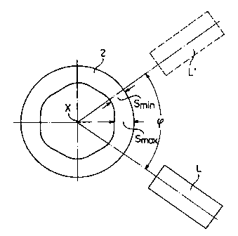
Fig. 1 shows a device according to the invention with
only one measuring head;
Fig. 2 shows a cross-section of the pipe with a
hexagonal inner polygon;
Fig. 3 shows the device according to the invention with
three measuring heads;
Fig. 4 explains in a schematic illustration the
principle of the invention; and
Fig. 5 show schematically the measuring head advancing
mechanism and adjustment possibilities for radius and height
adaptation relative to the rolling center.
14
CA 02326269 2006-04-10
DESCRI1?TION OF THE PRBFER~tED E~ODI1~NTS
Fig. 2 shows a device with only one measuring head L
which can be pivoted into the position L' by the angle
about the point of rotation X at the center of the pipe 2.
The hexagonal polygon is defined by the thinnest wall Sm~"
and the thickest wall Smax~ The shape of the polygon is
regular because the center of the outer circle and the
center of the polygon are located at the point of
intersection X of the two center lines. In Fig. 1, a
hexagonal polygon and a pivot angle cp of the scanner L of
70° is illustrated. For a hexagonal polygon a pivot angle
of 30° would be sufficient, as illustrated in Fig. 5, i.e.,
from $min t0 Smaxr in order to be able to reconstruct a
complete pipe cross-section. The angle of 70° thus provides
a doubled safety feature because it detects two mirror-
symmetrically arranged sections of the pipe so that a
comparison possibility results and a plausibility control of
the measured results is possible more easily.
The actual measuring device for contactless online wall
thickness measurement of hot-rolled pipes is comprised of at
least one compact laser ultrasound measuring head L1 that
can be adjusted relative to the pipe dimension to be
measured. The excitation and illumination lasers 8 are
CA 02326269 2000-11-17
arranged in a common housing of the measuring head Ll
together with the optical elements 9 (see Fig. 4) for
collecting the carrier light, which is reflected at the
surface of the pipe 3 and which contains the ultrasound
signal. The measuring head L1 is pivotable by means of a
pivot device (not represented) about a segment of the pipe 3
in the circumferential direction. In this context it is, in
principle, of no consequence which type of pivot device is
used; it is only important that a pre-determined segment of
the pipe circumference is measured.
Fig. 2 shows in this connection the cross-section of a
pipe 3 with a hexagonal inner polygon 4 whose center point Z
is spaced by the distance E from the center point Y of the
outer circle 5. Since this eccentric shape of the pipe is
formed by a circumferential spiral, the spacing E also
extends in the longitudinal direction of the pipe about the
center point Y with the consequence that the thinnest
location Smin and the thickest location Smax ( Fig. 1 ) of the
pipe 3 also rotate about the center point Y. The three
measuring heads L1 to L3 are distributed in the basic
position at an angle of 120° about the pipe with identical
spacing from the center point Y of the pipe. All three
measuring heads pivot in the same direction back and forth
about the angle cp about the pipe, i.e., measuring head L1 to
16
CA 02326269 2000-11-17
L1', L2 to L2' etc. The measuring head L1 is illustrated in
an exemplary fashion in the horizontal direction but can be
adjusted in its basic position such that its pivot angle is
symmetrical to the inner polygon; for a pivot angle ~ of,
for example, 70° slanted in the downward direction by 5°,
relative to the horizontal plane.
The pivotable measuring heads L1 to L3 have the
advantage that their basic angular position, respectively,
their pivot angle ~ can be changed during operation of the
rolling process. As is illustrated in Fig. 3 in another
example, the measuring heads L1 to L3 in their basic
position, based on the position of Fig. 2, can be changed
such that their pivot angles ~ partially overlap. In Fig.
3, the three measuring heads L1 to L3 are illustrated which
in the basic position are staggered relative to one another
by 70°. When the scanners are now pivoted by ~1 = ~2 = ~3 =
70°, the angle ~2 is scanned twice and such that the
measuring points have a defined offset relative to one
another. For each surface area unit, the number of
measuring points can thus be doubled or even tripled. It is
thus conceivable that the operator during the operation of
the rolling process adjusts the angular position of the
scanners so as to deviate from the basic (normal) position,
in which measurements are carried out with normal
17
CA 02326269 2000-11-17
resolution, such that across a certain length of the pipe
the measuring grid is condensed and, in this way,
practically an enlargement of the pipe cross-section can be
indicated (magnifying glass function).
With the aid of the schematic illustration of Fig. 4
the principle of the invention will be explained with the
example of a single channel measuring head.
The measuring system is comprised of the measuring head
L1 adjustable to the diameter of the pipe 3 to be measured
with corresponding supply elements 5 (compressed air,
cooling water) at the site, the electronic control and
evaluation device, the electric distribution station 6, as
well as the personal computer of the operator on the control
stage 7 of the SRR. Between measuring head L1 at the site,
the electric distribution station 6, and the control stage 7
greater distances are possible. In principle, the wall
thickness measuring device is configured for the rough
environment of a hot-rolling facility.
The measuring head L1 with a special housing with
- water-cooled front side and heat-resistant window of quartz
glass comprises essentially the following listed elements,
not represented because they are known in the prior art:
18
CA 02326269 2000-11-17
the ultrasound excitation branch with the head of the
flashlamp-pumped Nd:YAG pulse laser and the focusing lens,
the detection branch with the cw laser including controller,
the infrared filter, the expanding optic with deflection
mirror and deflection prism, an imaging lens with great
light transmitting power for collecting the ultrasound-
modulated light reflected at the pipe surface.
Also included (see Fig. 5) are in the area of the
measuring head L the sensor device, also not illustrated,
for recognizing the entry of the pipe for generating the
start/stop signal,
the measuring head advancing mechanism with pivot
device and adjusting possibilities for radius and height
adaptation to the rolling center (spacing h),
the manual or completely automatic dimension adaptation
for the pipe diameter change (spacing d),
the measuring head drive device (with motor in jogging
skip) with mechanical stop for servicing and the measuring
position,
the angle adjustment device (angle ~) adjustable for an
angle segment of approximately 30° in order to vary
downstream of the stretch reduction rolling mill for strong
polygon formation the measuring path between minimum and
maximum wall, i.e., to be able to pivot the measuring head,
19
CA 02326269 2000-11-17
in general, with automatic motoric angle adjustment with
drive, absolute value transducer, and end position
monitoring.
While specific embodiments of the invention have been
shown and described in detail to illustrate the inventive
principles, it will be understood that the invention may be
embodied otherwise without departing from such principles.