Sélection de la langue

Search

Sommaire du brevet 2326826 

Énoncé de désistement de responsabilité concernant l'information provenant de tiers

Une partie des informations de ce site Web a été fournie par des sources externes. Le gouvernement du Canada n'assume aucune responsabilité concernant la précision, l'actualité ou la fiabilité des informations fournies par les sources externes. Les utilisateurs qui désirent employer cette information devraient consulter directement la source des informations. Le contenu fourni par les sources externes n'est pas assujetti aux exigences sur les langues officielles, la protection des renseignements personnels et l'accessibilité.

Disponibilité de l'Abrégé et des Revendications

L'apparition de différences dans le texte et l'image des Revendications et de l'Abrégé dépend du moment auquel le document est publié. Les textes des Revendications et de l'Abrégé sont affichés :

  • lorsque la demande peut être examinée par le public;
  • lorsque le brevet est émis (délivrance).
(12) Brevet: (11) CA 2326826
(54) Titre français: COMPRESSEUR D'AIR DE LOCOMOTIVE AVEC MOTEUR SOUTENU PAR UN PALIER EXTERIEUR
(54) Titre anglais: LOCOMOTIVE AIR COMPRESSOR WITH MOTOR SUPPORTED BY OUTSIDE BEARING
Statut: Périmé
Données bibliographiques
(51) Classification internationale des brevets (CIB):
  • F04B 39/00 (2006.01)
  • B60T 17/02 (2006.01)
  • F04B 27/04 (2006.01)
  • F04B 35/04 (2006.01)
  • F04B 39/06 (2006.01)
  • F04B 39/12 (2006.01)
(72) Inventeurs :
  • VARNEY, JAMES (Etats-Unis d'Amérique)
  • CUNKELMAN, BRIAN L. (Etats-Unis d'Amérique)
  • GOETTEL, WALTER E. (Etats-Unis d'Amérique)
(73) Titulaires :
  • WESTINGHOUSE AIR BRAKE TECHNOLOGIES CORPORATION (Etats-Unis d'Amérique)
(71) Demandeurs :
  • WESTINGHOUSE AIR BRAKE TECHNOLOGIES CORPORATION (Etats-Unis d'Amérique)
(74) Agent: MACRAE & CO.
(74) Co-agent:
(45) Délivré: 2003-09-02
(22) Date de dépôt: 2000-11-23
(41) Mise à la disponibilité du public: 2001-12-14
Requête d'examen: 2000-11-23
Licence disponible: S.O.
(25) Langue des documents déposés: Anglais

Traité de coopération en matière de brevets (PCT): Non

(30) Données de priorité de la demande:
Numéro de la demande Pays / territoire Date
593,559 Etats-Unis d'Amérique 2000-06-14

Abrégés

Abrégé français

La présente invention fournit un assemblage de soutien à un élément rotatif d'axe mis en mouvement par un moteur. L'assemblage comprend un élément de base, un élément de soutien vertical connecté à l'élément de base et un élément de support monté sur l'élément de soutien vertical. Cet élément de support est connectable sur l'élément rotatif d'axe pour soutenir cet élément rotatif d'axe réduisant ainsi les mouvements verticaux et horizontaux superflus de cet élément rotatif d'axe tout en permettant à cet élément rotatif d'axe de tourner librement.


Abrégé anglais

The present invention provides an assembly for supporting a rotatable shaft member driven by a motor. The assembly comprises a base member, an upright support member connected to the base member and a bearing member mounted on the upright support member Such bearing member is connectable with the rotatable shaft member for supporting such rotatable shaft member thereby reducing extraneous vertical and horizontal movement of such rotatable shaft member while permitting such rotatable shaft member to rotate freely.

Revendications

Note : Les revendications sont présentées dans la langue officielle dans laquelle elles ont été soumises.


We claim:

1. An assembly for supporting one end of a rotatable shaft
member of a compressor driven by a motor, said assembly
comprising:

(a) a base member;

(b) a support member connected to and extending
substantially vertical from said base member and being
substantially perpendicular to a longitudinal and horizontally
disposed axis of said rotatable shaft member; and

(c) a bearing member carried by said support member having
an outer surface engageable with an inner surface of said
support member and an inner surface engageable with an outer
surface of such rotatable shaft member and connectable with such
one end of such rotatable shaft member that is opposite an end
of such rotatable shaft member connected to a hub and a wheel of
a cooling fan of such compressor for supporting such rotatable
shaft member in a manner so as to thereby reduce extraneous
vertical and horizontal movement of such rotatable shaft member
while permitting such rotatable shaft member to rotate freely.

2. An assembly for supporting one end of a rotatable shaft
member of a compressor driven by a motor, according to claim l,


9


wherein said base member is disposed as part of a base of such
compressor connected to said motor and said assembly.

3. An assembly for supporting one end of a rotatable shaft
member of a compressor driven by a motor, according to claim 1,
wherein said base member of said assembly is a separate base for
said assembly and is independent of a base of such compressor.

4. An assembly for supporting one end of a rotatable shaft
member driven by a motor, according to claim 1, wherein said
bearing member is a split type bearing.

5. An assembly for supporting one end of a rotatable shaft
member driven by a motor, according to claim 1, wherein said
support member is an A-frame.

6. An assembly for supporting one end of a rotatable shaft
member driven by a motor, according to claim 5, wherein said
bearing member is mounted on an apex of said A-frame support
member.

7. An assembly for supporting one end of a rotatable shaft
member driven by a motor, according to claim 1, wherein a first


10


end of said support member is connected to said base member and
a portion of said upright support member is connected to a motor
cover of a motor housing.

8. An assembly for supporting one end of a rotatable shaft
member driven by a motor, according to claim 7, wherein said
first end of said support member is connected to said base
member and a radially opposed second end is connected to such
motor cover of such motor housing.

9. In combination with a multi-cylinder two-stage air
compressor in which an electric motor drives a rotatable shaft
member of said air compressor, the improvement comprising an
externally mounted assembly for supporting one end of said
rotatable shaft member of said air compressor, said externally
mounted assembly including:
(a) a base member;
(b) a support member connected to and extending
substantially vertical from said base member and being
substantially perpendicular to a longitudinal and horizontally
disposed axis of said rotatable shaft member; and

11


(c) a bearing member carried by said support member having
an outer surface engageable with an inner surface of said
support member and an inner surface engageable with an outer
surface of said rotatable shaft and connectable with said one
end of said rotatable shaft member for supporting said rotatable
shaft member in a manner so as to thereby reduce extraneous
vertical and horizontal movement of said rotatable shaft member
while permitting said rotatable shaft member to rotate freely.

10. The combination, according to claim 9, wherein said
base member is one of being incorporated as a single base for
said air compressor and said externally mounted assembly and as
a separate base for said externally mounted assembly.

11. The combination, according to claim 10, wherein said
base member of said externally mounted assembly is a separate
base for said externally mounted assembly.

12. The combination, according to claim 11, wherein said
bearing member is a split type bearing.

13. The combination, according to claim 12, wherein said
bearing member is connected to said one end of said rotatable

12


shaft member that is opposite an end of said rotatable shaft
member connected to a hub and wheel of a cooling fan of said air
compressor.

14. The combination, according to claim 9, wherein said
support member is an A-frame.

15. The combination, according to claim 14, wherein said
bearing member is mounted on an apex of said A-frame upright
support member.

16. The combination, according to claim 9, wherein a
first end of said upright support member is connected to said
base member and a portion of said upright support member is
connected to a motor cover of a motor housing.

17. The combination, according to claim 16, wherein said
first end of said upright support member is connected to said
base member and a radially opposed second end is connected to
said motor cover of said motor housing.

13

Description

Note : Les descriptions sont présentées dans la langue officielle dans laquelle elles ont été soumises.

CA 02326826 2002-10-16
?LOCOMOTIVE AIR COMPRESSOR WITH i~OTOR
SUPPORTED BY OUTSIDE BEARING
FIELD OF INVENTION
The present invention relates, in general, to an air-cooled
multi-cylinder, two-stage air compressor and motor combination
for a railway locomotive and, more particularly, the present
invention relates to a crankshaft of such air compressor driven
by such motor being supported by an outside bearing.
CROSS REFERENCE TO RELATED APPLICATIONS
The invention taught in this patent application is closely
related to the invention taught in the following co-pending
patent application, LOCOMOTIVE AIR COMPRESSOR WITH AN ELECTRIC
MOTOR SUPPORTED BY AN EXTERNAL BEARING, Serial No. 2,326,788
which is being filed concurrently herewith.
BACKGROUND OF THE INVENTION
It is well known that multi-cylinder air compressors are
used on freight and passenger locomotives to supply compressed
air to the operating and control equipment of a railway air
brake system. Many of these prior art air compressors have a
pair of low pressure cylinders and a high pressure cylinder
mounted on and supported by a crankcase in the usual manner and
1

CA 02326826 2000-11-23
contain pistons which are actuated by connecting rods driven by
a rotary crankshaft. One end of the crankshaft is coupled with
and driven by a suitable rotatable prime mover, such as an
electric motor. The other end of the crankshaft is keyed and
threadably attached by a locknut to the hub and wheel of a
cooling fan assembly.
There are advantages of having the compressor directly
driving the cooling fan. When the demand and speed of the air
compressor increase, the speed and cooling capacity of the fan
is proportionally increased. The fan can only stop turning
when the compressor stops working or ceases to rotate. It has
been found that the use of a separate electric motor for
driving the cooling fan is unreliable since failure of the
motor would result in the loss of the cooling effect and could
allow the temperature of the rotating compressor to rise to
dangerously high levels which could cause deterioration of the
lubricating oil and could result in seizure of the air
compressor.
The crankshaft driven by the electric motor does not, in
prior art, have any support on the motor end of the shaft.
This is the opposite end of the shaft from the fan. As the
shaft rotates, in time, it may tend to vibrate and may possibly
wobble. Any movement of the shaft, other than the rotatable
2

CA 02326826 2000-11-23
movement which it is designed to have, may cause problems with
the motor.
Proper operation requires that there be a space between
the stator and the rotating portion of the motor. This space
must be maintained. If the rotor contacts or rubs against the
stator, problems with the motor may occur. On the other hand
it is also important to keep the space between the stator and
rotor to a minimum because as the space increases there is a
loss of efficiency and of the power of the motor. Thus, the
space is necessary but it must be kept as small as possible.
When the shaft vibrates or wobbles it may cause the rotor to
rub against the stator and, thus, adversely affect the motor.
SUMMARY OF THE INVENTION
The present invention provides an assembly for supporting
a rotatable shaft member driven by a motor. The assembly
comprises a base member, an upright support member connected to
the base member and a bearing member mounted on the upright
support member. Such bearing member is connectable with the
rotatable shaft member for supporting such rotatable shaft
member thereby reducing extraneous vertical and horizontal
movement of such rotatable shaft member while permitting such
rotatable shaft member to rotate freely.
A second embodiment of the invention provides that in
combination with a multi-cylinder two-stage air compressor in
3

CA 02326826 2000-11-23
which an electric motor is used to drive a rotatable shaft
member of said air compressor, there is an externally mounted
assembly for supporting the rotatable shaft member of the air
compressor. Such externally mounted assembly comprises a base
member, an upright support member connected to the base member
and a bearing member mounted on the upright support member.
Such bearing member is connectable to the rotatable shaft
member for securing the rotatable shaft member thereby reducing
extraneous vertical and horizontal movement of the rotatable
shaft member while permitting such rotatable shaft member to
rotate freely.
OBJECTS OF THE INVENTION
It is, therefore, one of the primary objects of the
present invention to provide a support for the crankshaft
external to the motor housing in an air compressor/motor
combination so as to reduce any vibration of the shaft.
It is also an object of the present invention to provide
an outside support for the crankshaft in an air
compressor/motor combination so as to reduce the possibility of
the rotor rubbing against the stator.
An additional object of the present invention is to
provide a support for the crankshaft in an air compressor/motor
combination that is mounted on the base of the compressor unit.
4

CA 02326826 2002-10-16
These and various other objects and advantages of this
invention will become apparent after a full reading of the
following detailed description, particularly, when read in
conjunction with the attached drawings as described below and
the appended claims.
BRIEF DESCRIPTION OF THE DRAWINGS
Figure 1 is an axonometric prior art drawing of a
multi-cylinder, two stage air compressor.
Figure 2 is a block schematic diagram of an embodiment of
the invention in combination with a multi-cylinder, two stage
air compressor of the type shown in Figure 1.
Figure 3 is schematic diagram of a second embodiment of the
invention showing an upright support member as an A-frame.
Figure 4 is a block schematic diagram of an embodiment of
the invention in combination with a multi-cylinder, two stage
air compressor of the type shown in Figure lin which the base
member of the air compressor includes the base member for the
support member and showing the motor cover and motor housing in
relation to the present invention.
Figure 5 is a block schematic diagram of an embodiment of
the invention in combination with a multi-cylinder, two stage
air compressor of the type shown in Figure 1 in which the base
member of the air compressor and the base member for the support
member are separate bases.

CA 02326826 2002-10-16
Figure 6 is an axonometric drawing of a split type bearing
according to an embodiment of the invention.
BRIEF DESCRIPTION OF THE
PRESENTLY PREFERRED AND ALTERNATE
EMBODIMENTS OF THE INVENTION
Prior to proceeding with the more detailed description of
the present invention it should be noted that, for the sake of
clarity, identical components which have identical functions
have been designated by identical reference numerals throughout
the several views illustrated in the drawings.
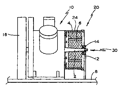
Reference is now made to Figure 2. Illustrated therein is
a block diagram of the present invention in combination with a
multi-cylinder, two stage air compressor, generally designated
as 10, coupled with an electric motor, generally
5a

CA 02326826 2000-11-23
designated as 20. Such multi-cylinder, two stage air
compressor 10 contain pistons which are actuated by connecting
rods driven by a rotary crankshaft 2. One end of the
crankshaft 2 is to the hub and wheel of a cooling fan
assembly 16. The other end of the crankshaft 2 is driven by an
electric motor 20. In time the crankshaft 2 as it rotates may
tend to vibrate or wobble. Any movement of the crankshaft 2
other than the rotatable movement which it is designed to have
can create problems.
Proper operation of the motor requires that there be a
space between the stator 4 and the rotor 6, which is the
rotating portion of the motor. This space must be maintained.
If rotor 6 comes into contact with or rubs against the
stator 4, problems with the motor 20 may occur. It is also
important that this space be kept to a minimum because as the
space increases there is a loss of efficiency and of the power
of the motor.
The present invention provides an external support,
generally designated 30, to support the crankshaft 2 and thus
prevent or at least minimize any extraneous vertical or
horizontal movement of the crankshaft 2. The external mount
comprises a base 8. As pictured in Figure 2 the base 8 forms
a base upon which the compressor 10 sits. However, the base 8
may be of various lengths and may not include a portion under
6

CA 02326826 2000-11-23
such compressor 20. An upright support member 12 is connected
to the base 8. There is a bearing member 14 mounted on such
upright support member 12. Such bearing member 14 is
connectable with the crankshaft 2 of such air compressor 10.
Such bearing member 14 and such upright support member 12
supports the crankshaft thereby minimizing any extraneous
movement of the crankshaft 2. Since the bearing member 14
freely rotates it does not impede any rotatable movement of the
crankshaft 2. In an embodiment of the invention such bearing
member 14 is a split type bearing. In another embodiment of
the invention the bearing member 14 is connected to an outer
end of such crankshaft 2.
The upright support member 12 may be connected to the
motor cover that is presently used to enclose such motor 20 by
modifying such motor cover such that the bearing member 14 can
secure the crankshaft 2. However, it is within the scope of
the invention that such upright support member 12 may be used
to replace the present motor cover of such motor 20.
As mentioned previously such base 8 may be incorporated
with the base of the compressor or it may remain as a separate
portion. Such external mount 30 may be included in new
compressor assemblies and it may be retrofitted into air
compressor units that are presently in use.
7

CA 02326826 2000-11-23
Illustrated in Figure 3 is another embodiment of the
invention in which the upright support member 12 is in the
form of an A-frame. In this embodiment such bearing
member 14 is mounted on the apex of the upright support
member 12.
While both the presently preferred and a number of
alternative embodiments of the present invention have been
described in detail above it should be understood that various
other adaptations and modifications of the present invention
can be envisioned by those persons who are skilled in the
relevant art of air compressor systems without departing from
either the spirit of the invention or the scope of the appended
claims.
8

Dessin représentatif
Une figure unique qui représente un dessin illustrant l'invention.
États administratifs

Pour une meilleure compréhension de l'état de la demande ou brevet qui figure sur cette page, la rubrique Mise en garde , et les descriptions de Brevet , États administratifs , Taxes périodiques et Historique des paiements devraient être consultées.

États administratifs

Titre Date
Date de délivrance prévu 2003-09-02
(22) Dépôt 2000-11-23
Requête d'examen 2000-11-23
(41) Mise à la disponibilité du public 2001-12-14
(45) Délivré 2003-09-02
Expiré 2020-11-23

Historique d'abandonnement

Il n'y a pas d'historique d'abandonnement

Historique des paiements

Type de taxes Anniversaire Échéance Montant payé Date payée
Requête d'examen 400,00 $ 2000-11-23
Enregistrement de documents 100,00 $ 2000-11-23
Le dépôt d'une demande de brevet 300,00 $ 2000-11-23
Taxe de maintien en état - Demande - nouvelle loi 2 2002-11-25 100,00 $ 2002-11-06
Taxe finale 300,00 $ 2003-06-04
Taxe de maintien en état - brevet - nouvelle loi 3 2003-11-24 100,00 $ 2003-11-03
Taxe de maintien en état - brevet - nouvelle loi 4 2004-11-23 100,00 $ 2004-10-07
Taxe de maintien en état - brevet - nouvelle loi 5 2005-11-23 200,00 $ 2005-10-06
Taxe de maintien en état - brevet - nouvelle loi 6 2006-11-23 200,00 $ 2006-10-06
Taxe de maintien en état - brevet - nouvelle loi 7 2007-11-23 200,00 $ 2007-10-09
Taxe de maintien en état - brevet - nouvelle loi 8 2008-11-24 200,00 $ 2008-11-05
Taxe de maintien en état - brevet - nouvelle loi 9 2009-11-23 200,00 $ 2009-11-12
Taxe de maintien en état - brevet - nouvelle loi 10 2010-11-23 250,00 $ 2010-11-04
Taxe de maintien en état - brevet - nouvelle loi 11 2011-11-23 250,00 $ 2011-10-13
Taxe de maintien en état - brevet - nouvelle loi 12 2012-11-23 250,00 $ 2012-10-10
Taxe de maintien en état - brevet - nouvelle loi 13 2013-11-25 250,00 $ 2013-10-09
Taxe de maintien en état - brevet - nouvelle loi 14 2014-11-24 250,00 $ 2014-10-29
Taxe de maintien en état - brevet - nouvelle loi 15 2015-11-23 450,00 $ 2015-10-28
Taxe de maintien en état - brevet - nouvelle loi 16 2016-11-23 450,00 $ 2016-11-02
Taxe de maintien en état - brevet - nouvelle loi 17 2017-11-23 450,00 $ 2017-11-01
Taxe de maintien en état - brevet - nouvelle loi 18 2018-11-23 450,00 $ 2018-10-31
Taxe de maintien en état - brevet - nouvelle loi 19 2019-11-25 450,00 $ 2019-10-29
Titulaires au dossier

Les titulaires actuels et antérieures au dossier sont affichés en ordre alphabétique.

Titulaires actuels au dossier
WESTINGHOUSE AIR BRAKE TECHNOLOGIES CORPORATION
Titulaires antérieures au dossier
CUNKELMAN, BRIAN L.
GOETTEL, WALTER E.
VARNEY, JAMES
Les propriétaires antérieurs qui ne figurent pas dans la liste des « Propriétaires au dossier » apparaîtront dans d'autres documents au dossier.
Documents

Pour visionner les fichiers sélectionnés, entrer le code reCAPTCHA :


Pour visualiser une image, cliquer sur un lien dans la colonne description du document. Pour télécharger l'image (les images), cliquer l'une ou plusieurs cases à cocher dans la première colonne et ensuite cliquer sur le bouton "Télécharger sélection en format PDF (archive Zip)" ou le bouton "Télécharger sélection (en un fichier PDF fusionné)".

Liste des documents de brevet publiés et non publiés sur la BDBC .

Si vous avez des difficultés à accéder au contenu, veuillez communiquer avec le Centre de services à la clientèle au 1-866-997-1936, ou envoyer un courriel au Centre de service à la clientèle de l'OPIC.


Description du
Document 
Date
(yyyy-mm-dd) 
Nombre de pages   Taille de l'image (Ko) 
Abrégé 2000-11-23 1 16
Description 2000-11-23 8 264
Revendications 2000-11-23 6 148
Dessins 2000-11-23 3 52
Dessins 2001-07-05 2 31
Dessins représentatifs 2001-11-20 1 10
Page couverture 2001-12-07 1 39
Description 2002-10-16 9 277
Revendications 2002-10-16 5 134
Dessins 2002-10-16 4 59
Dessins représentatifs 2003-07-29 1 11
Page couverture 2003-07-29 1 40
Correspondance 2001-01-09 1 2
Cession 2000-11-23 3 123
Cession 2001-05-25 2 100
Poursuite-Amendment 2001-07-05 3 74
Poursuite-Amendment 2002-04-16 4 153
Poursuite-Amendment 2002-10-16 17 435
Correspondance 2003-06-04 1 33