Note : Les descriptions sont présentées dans la langue officielle dans laquelle elles ont été soumises.
'' CA 02327093 2000-10-02
Plasma torch with a microwave transmitter
Soeci fication
The invention relates to a plasma torch with a microwave transmitter,
according to the kind of patent claims which, for example, is used to coat
surfaces and to produce radicals.
Known magnetron-ion sources employ a magnetron for generating an
alternating electric field; refer to DE 37 38 352 Al. It is an disadvantage
that a quartz dome and external magnetic fields are required to generate
the gas plasma. The intensive magnetic field in the discharge chamber is
used to match the cyclotron frequency to that of the microwave
generator. The operation of the microwave gas discharge takes place
without electrodes. Furthermore, the operation requires a cooling of the
device. Such plasma generators are of a complex structure and are
limited in their dimensions. The technical expenditures for microwave
gas discharges systems are high. It is not feasible to transmit high
powers, and it is not evident that plasmas of high density are stable when
high powers are concerned.
Devices for generating plasmas by microwaves, as known from, for
example, DE 3905303 C2, DE 3915477 C2. US 5349154 A, generally
use quartz tubes. A magnetron (microwave transmitter unit) is secured to
n ~ r ~_r~__t__ L..11..___ '.7.. 'T1... E...~
G5 UIIe ellu of a reGlQll~ul~tl lllJllVw guiuc. iiic gcucra~cu iilicruwaveS
pass
through the hollow guide and impinge, at the other end of the hollow
guide, upon a quartz glass insert through which a special gas flows. The
flowing originates from a low pressure maintained in the recipient. In the
quartz glass insert a plasma is generated by the microwave energy, and
the plasma flows through the quartz glass insert into the recipient. The
method is characterized by not having any electrodes.
Such devices exhibit the following disadvantages:
- The hottest site and the center of the plasma are located in that portion
1
CA 02327093 2000-10-02
of the quartz glass insert, which is arranged within the rectangular
hollow guide. Hence, the energy is transformed before the recipient
rather than within the same and, at a respective application, too little
radicals are provided for the operation process.
- A high rate of wall effects occur within the quartz glass.
- The mass throughput and the effective pressures of 500 Pa to 3 kPa are
too low.
- The quartz glass insert is not suited for any large-scale technical
continuous operation. Due to the unintentional high temperatures the
quartz glass insert shows melting effects, or there have to be
additionally provided expensive cooling devices.
- The efficiency of the energy exploitation is low.
- It is difficult to maintain the vacuum tightness at the sealing faces.
- In the course of mounting and dismounting, respectively, and due to the
thermal expansion of the metallic components it can be possible that
the glass will be destroyed.
Furthermore, devices are known, in which a cross-coupling of a
rectangular hollow guide with a coaxial guide is provided. Also in this
case, a microwave generating device and a microwave transmitter
device, respectively, i.e. a magnetron, are secured to one end of a hollow
guide. The generated microwaves pass through the hollow guide and
impinge upon a conductive longitudinally extending nozzle. The hollow
guide is closed by a short-circuit slide. In this way, the resulting
L~ electromagnetic wave is tuiia'oie. Suci1 a known aiiaugeiiicnt i,au be
designed with a quartz tube (DE 195 11 915 C2) or without one (US
4,611,108 A). The last-mentioned embodiment (also refer to EP 0 104
109 Al) neither includes a thermal insulation nor a gas insulation of the
discharge cavity relative to the coupling out. Apart from the fact that
when using quartz tubes the specific disadvantages occur as mentioned
above, this cross-coupling features the following disadvantages:
- The exploitation of the microwave output is of low efficiency.
- Energy losses occur at the cross-coupling between the rectangular
hollow guide and the coaxial guide.
2
CA 02327093 2000-10-02
- The entire construction is complicated.
- The maximal operation pressure and the mass throughput are to little.
From US 4,473,736 A a plasma generator is known, in which a cavity
and a coaxial guide are capacitively coupled. Insulating thin disks
supporting the electrode are arranged distributed along the entire cross-
section of the cavity and the coaxial guide. Apart from not being a
hollow wave guide, this arrangement is not suited for an impedance
matching and for obtaining a low-reflective hollow wave conduction.
Furthermore, a burner for a microwave plasma is known, a device
including this burner and a method for the use of the same in producing
powder (EP 0296921 A1). This device utilizes a coupling member for
coupling the microwaves out from a rectangular hollow guide and in into
a coaxial guide, the inner guide of which is designed as a gas nozzle and
at one end of which a burning plasma flame is adapted to be ignited at
ambiance. Thus, a gas-tight or thermal insulation and an elimination of
parasitic discharges is not ensured. The provided gas screening is in no
direct relation to the plasma flame and to the coupling member.
Finally, a high-frequency discharge generator with an auxiliary electrode
is known from US 3 353 060 A, which couples the waves originating
from the high-frequency discharge generator via a rectangular hollow
guide into a coaxial guide (E-coupling), at the open end of which the
inner conductor is used as an electrode and is pretending to generate a
freely burning plasma flame. The gas supply thereby takes place at the
other and closed end of the coaxial guide. iveiiher is iiie~e provided a
gas-tight or thermally insulating separation of the discharge range from
the coupling-out member, nor the formation of a standing wave in the
discharge range. Moreover, the gas supply can scarcely be matched to
the plasma flame.
Hence, it is an object of the present invention to provide a plasma torch
that generates plasma with high densities in a range near normal
pressure. Thereby high powers are capable to be transmitted. The plasma
torch shall be capable of realizing a stable discharge in a defined
discharge zone at an efficient exploitation of the microwave energy.
3
CA 02327093 2000-10-02
Susceptible quartz tubes or quartz domes for generating plasmas have to
be avoided. There is, in total, a simple setup of a plasma torch aimed at,
which efficiently couples the microwaves out of the waveguide and in
into the plasma.
According to the invention the object is realized by the features of the
Patent Claim 1. As a matter of fact, it is initially irrelevant whether or not
the coaxial guide is, in a cross-coupling, directed transversally to the
hollow guide or, in an axial coupling, in parallel to the hollow guide,
whether consequently their longitudinal axes preferably include a right
angle or whether or not their longitudinal axes substantially coincide.
The plasma torch (plasma generator) comprises a vacuum chamber and a
magnetron, which within the vacuum chamber generates itself a field
intensity sufficient for plasma formation. A recipient succeeding the
coaxial guide is under a pressure of 100 Pa to 10 kPa, this pressure is
suited for the formation of a plasma. A high efficiency is attained
irrespective of the kind of coupling. The inv entional plasma torch does
without a cooling and without magnet coils due to its simple axial setup
with an antenna as an electrode. The advantage in using a hollow wave
guide instead of an a. c.-waveguide lies in the fact that the microwave
output is not only coupled in the plasma in the vicinity of the nozzle,
where there are the highest field intensities, but via the hollow space
waves along the entire hollow guide axis. Such a design permits a quasi-
electrodeless coupling-in that reduces the thermal stress of the nozzle.
AQVanIageUl151y, tile hollow electrode 1s de~igilcd a~ a tiuuCatcd con a and
secured to the non-conductive intermediate member that is connected to
the coaxial guide via a preferably disk-shaped mount. The nozzle is
connected to a gas inlet through this intermediate member. The mounting
disk is flanged to the coaxial guide and to the hollow guide.
Advantageously, the hollow electrode is designed as a truncated cone,
the shell of which is in opposition to the recipient. At this side, the
hollow electrode is provided with an exchangeable nozzle that is
inserted, preferably screwed into its hollow space; the nozzle comprises
four exit orifices for the operation gas, the exit orifices are arranged in
4
CA 02327093 2000-10-02
the exit plane, regularly spaced from each other on a circle centered
about the exit plane. In this way, an optimal directing of the microwave
to the exit plane (nozzle tip) is achieved and a favorable energy input into
the plasma flame is attained. A nozzle adapted for high temperatures
S preferably consists of a metal-ceramic alloy. An electrically non-
conductive insulator thermally insulates the space of the plasma flame
from the coupling of the coaxial guide to the hollow guide. An
advantageous solution for the operation of the plasma torch is obtained in
rendering the electrode axially and, if necessary, radially adjustable. In
the case of cross-couplings, a brass member and a connection member
preferably connect the nozzle and the intermediate member to a gas inlet.
The brass member in any case ensures the electromagnetic coupling of
the hollow guide and coaxial guide. The hollow guide, preferably a
rectangular hollow guide, of the cross-coupling is provided with two
1 S screws for tuning the electromagnetic wave to the coupling. In the case
of the hollow guide, preferably a round hollow guide, of the axial
coupling, the tuning is advantageously carried out in that its length is
variable. To this end the hollow guide consists of, for example, two parts
that can be telescope like slid one into the other, also during operation.
One of the tubes can be provided with longitudinal slots and in-between
remaining resilient lugs. A microwave seal is advantageously provided in
an annular groove located between the tubes in an overlapping range. At
the transition from the coaxial guide to the recipient a vacuum
passageway for the electrode and the operation gas is provided; in this
GJ Way an Cf11C:1CIit l;oupiillg of l he eieC,irolilagucti~, wave is obtain
ed.
In the following, the invention will be explained in more detail by two
schematical drawings illustrating two embodiments. There is shown in:
Fig. 1 a longitudinal cross section of a cross-coupling of a
3Q rectangular hollow guide with a coaxial guide;
Fig. 2 a longitudinal cross section of an axial coupling of a round
hollow guide with a coaxial guide;
Fig. 3 an enlarged representation of a front view of the nozzle.
S
CA 02327093 2000-10-02
In Fig. l, a cylindrical coaxial guide 2 having a longitudinal axis Y-Y is
coupled by a coupling member 3 in the vicinity of one of its ends to a
rectangular hollow guide 1 with a longitudinal axis X-X in such a way
that the longitudinal axis X-X and Y-Y are at right angles to each other.
The coupling member 3 is designed like a bowl with a central opening 4
and a circumferential flange 5 and contains a disk 6 for engaging an
intermediate member 7 made of insulating material. By way of a ring 8
screwed to the circumferential flange 5, the disk 6 is rigidly and tightly
connected to the coupling member 3. The central opening 4 in the
coupling member 3 corresponds to a same opening 9 in the rectangular
hollow guide 1. This opening is also surrounded by a flange 10, to which
the coupling member 3 is screwed on tightly. The ring 8 is the end-
portion of a hollow conductor 20 that comprises an insulator 11 at the
other end of which a recipient 12 is provided. The mounting disk 6, the
intermediate member 7, and the insulator 11 are designed strong enough
and form together a gas-tight, thermally insulating crossover, however
permitting passage of microwaves, between the rectangular hollow guide
1 and the hollow conductor 20. The intermediate member 7 additionally
must have dielectric properties that ensure a low-reflection waveguiding
at the crossover.
A cone-shaped electrode 13 made of a metal-ceramic alloy is secured to
that side of the intermediate member 7 facing the recipient 12. The
electrode 13, as is the intermediate member 7, is provided with an axial
passageway 14 into which at the free end of the electrode 13 a nozzle 22
is secured or exchangeabiy inserted, preferably 'oy screwing. T h a
longitudinal axis of the electrode 13 coincides with the axis Y-Y. On the
other side of the intermediate member 7, a brass member 16, which is
provided with an axial bore 15, is connected to the passageway 14; an
insulating connecting member 17 in continuation of the axial bore 15 is
attached to the brass member 16 and leads to a gas inlet 18. The
connecting member 17 is supported by a flat mount 19 which is tightly
screwed to the rectangular hollow guide 1. The cylindrical hollow
conductor 20 and the electrode 13 together form a coaxial guide 2. The
electrode 13, which is in the shape of a truncated cone, is positioned in a
6
CA 02327093 2000-10-02
respective recess 21 of the insulator 11 in such a way that the nozzle 22
projects beyond the insulator 11 on the side of the recipient.
The rectangular hollow guide 1 is provided with a magnetron 23 at its
other end, the magnetron generates microwaves, which are transmitted
through the guide 1. Two screws (steps) 24 are provided for for affecting
microwaves fort the coupling.
The microwaves generated by the magnetron 23 pass through the guide 1
and are tuned by the screws 24 to the coupling. By way of the cross-
coupling a longitudinal wave is coupled out into the coaxial guide 2 so
that an axial electromagnetic field results. The cross-coupling consists of
a coupling rod that is substantially identical to the electrode 13, with
which the coupling rod projects into the round hollow conductor 20, both
together form the coaxial guide. The coupling rod 13 has the task to
direct the operation gas and to assist in generating a plasma and a plasma
torch 25, respectively, at the orifice of the nozzle 22. The gas supply into
the coupling rod is provided from the external gas inlet 18 via the bores
15 in the connecting member 17 made of teflon and in the brass member
16, and via the passageway 14 of the intermediate member 7, which is
also made of teflon. The brass member 16 also ensures a good coupling
of the microwave. The electrode 13 is secured in and insulated against
the coaxial guide 2 by the connecting member 7. The geometry of the
electrode 13 is optimally adapted to the requirements of the procedure. It
ensures a maximal dielectric strength. Its favorable length is important
for its operation, which length can be varied by adjusting the passageway
2~ 14 by Way Uf the LllPCad II1 Llle eleGtrodC 13. Il.s CrUSS-seCl.I0I1 IS SO
selected that the coaxial guide 2 ensures an optimal guiding of the
electromagnetic wave and that the highest field strength is obtained at the
tip of the nozzle. This is very important since the plasma is ignited at the
site of the greatest field strength. The nozzle 22 is made of a special
material. It consists of a compound material, which has ceramic
components and is metallically conductive. The task of the ceramics is to
thermally insulate the plasma cloud from the electrode 13. The plasma is
operable up to a pressure of 35 kPa. A considerably greater mass
throughput can be obtained by that. This is a great advantage since
7
CA 02327093 2000-10-02
considerably more co-reactants can be generated in a respectme process.
Thus it is feasible to strongly reduce the process times due to the
considerably increased mass throughput. A further advantage of such a
burner lies in the fact that these parameters can also be obtained with air
as a process gas. Thus, one can do without expensive additional gases
such as, for example, noble gases (argon).
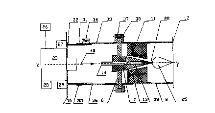
In Fig. 2 an air-cooled magnetron 23 connected to a control device 26 is
mounted on a base plate 30 together with a fan 27, a thermo-regulator 28,
and a heating-current transformer 29. The magnetron 23 for generating
the microwaves has an output of 2 kW and emits electromagnetic waves
at a stable frequency of 2.45 GHz and a wavelength of 12.24 cm. Its
output can be linearly controlled by the control device 26 between 10%
and 100% of the maximal power. The thermo-regulator with a thermal
circuit-breaker is connected to the resonator of the magnetron 23. At a
temperature of 120°C the thermo-regulator turns OFF the magnetron for
safety reasons.
The base plate 30 is secured to a round hollow guide 31 that comprises
an internal tube 32 which has a diameter of 100 mm and a wall thickness
of 2 mm, and an external tube 33 which has a diameter of 104 mm and a
wall thickness of 2 mm. The tubes 32, 33 are well-fitted one into the
other and can be, telescope-like, mutually and slidingly displaced. They
can be mutually fixed by a clamping screw 34. The external tube 33 is
provided with longitudinal slots 35 (only one visible) in order to create a
certain squeezing when the tubes are displaced, so that resilient lugs at
the external tube 33 result between the slots 35 which slightly press
against the interior tube, thus substantially preventing an unintentional
mutual displacement of the two tubes 32, 33 even when the clamping is
released. Simultaneously, the electrical contact between the tubes 32, 33
is improved thereby, and flash-overs between the tubes are avoided. In
order to ensure a microwave sealing of the round hollow guide 31, a
microwave seal 36, for example, in the form of a metallic gauze, can be
inserted into the annular groove between the two tubes 32, 33. The
external tube 33 is provided with a flange 37 at that of its ends facing
8
CA 02327093 2000-10-02
away from the magnetron 23. This flange 37 provides for an axial
coupling to a following coaxial guide 2 which has a common
longitudinal axis X-Y with the round hollow guide 31. This coupling
provides for coupling out of a longitudinal wave into the coaxial guide 2,
and an axial electrical field results.
The coaxial guide 2, as well as a subsequent recipient 12 attached
thereto, have the same diameter and cross-section, respectively, as the
external tube 33. Thereby, the recipient 12 simultaneously fulfills the
task of a hollow guide that prevents a lateral propagation of the waves,
and in this way couples-in the microwave power into the plasma 25 over
a considerable path behind the nozzle 22 along the axis X-Y (also along
the axis Y-Y in Fig. 1). The coaxial guide 2 has also a flange 38 at its end
which is facing the round hollow guide 31. This flange 38 matches the
flange 37 and is screwed to the latter and forms with the latter a
coupling member which corresponds to the coupling member 3 in Fig. 1.
Both flanges 37, 38 encompass the circumference of an engaging disk
made of any desired material (aluminium, quartz glass) and hermetically
and firmly support the disk. The interior conductor 39 of the coaxial
guide 2 is suspended electrically insulated in this disk 6 via an
intermediate member 7 made of PTFE. The use of Teflon has the
advantage that it is easily workable and that it ensures a permanent
vacuum tightness. Furthermore, this vacuum passage fulfills the task of
passing the microwave on to the recipient 12 and of a thermal insulation
of the hollow guide 32 from the hot plasma 25. The interior conductor 39
2J prUVldes Vr t he coiipiiilg of tile rolllid hollow guide alid tile
iCCipiCIii, for
the supplying gas, and for the expansion of the gas into the recipient 12
via a nozzle 22 screwed into an electrode 13. In order to tune the
microwave, the position of the interior conductor 39 in the coaxial guide
2 and its length are adjustable. The electrode 13 is secured to the
intermediate member 7 and, as the latter does, has a passageway 14 for
the gas supply. A compressed-air hose 40 made of PE (polyethylene) can
be connected to this passageway 14 via a brass member (similar to that in
Fig. 1 ). The intermediate member 7, the electrode 13, and the nozzle 22
form an antenna, the outer diameter of which is 20 mm. The longitudinal
9
CA 02327093 2000-10-02
axis of the antenna coincides with the axis X-Y. The plasma 25 ignites at
the nozzle 22 screwed into the end of the antenna. A detachable
connection between the electrode 13 and the nozzle 22 is important, to
enable exchange or renewal of the nozzle 22. Since the nozzle is exposed
to very high thermal loads it is made of highly heat-resistant steel; for
example, a metallic alloy is used having a maximal operation
temperature of 1425°C. This material is characterized in that the
nozzle
22 is metallic conductive and forms a ceramic surface under the
influence of high temperatures that can resist the high temperatures.
Since the frequency of the microwaves used lies below the plasma
frequency, it can not propagate within the plasma 25. Hence, in order to
realize as good as possible an energy input into the plasma 25, the
surface of the plasma cloud has to take a maximum. Therefore, the
nozzle 22 provides for a strong vorticity of the plasma 25. To this end
and according to Fig. 3, four abaxial gas exit orifices 43 are provided in
the exit plane 41 of the nozzle 22, in a preferably regular arrangement on
a circle 42, each gas exit orifices having a diameter of 1 mm. In order to
thermally insulate the plasma flame from the flanges 37, 38 and from the
disk-shaped mount 6, respectively, a thermal insulator 11 is arranged
between the disk-shaped mount 6 and the plasma torch 25, the electrode
13 and the nozzle 22 projecting through the thermal insulator 11. Just as
the coaxial guide 2, the recipient 12 consists of a tube with a diameter of
104 mm, a wall thickness of 2 mm and a length of 300 mm. It can be
provided with not shown means for temperature measurement, for
pumping off; and for observing the name. Hdvantageousiy, air is used as
an operation gas. The operation of the plasma 25 is possible up to a
pressure of 100 kPa. With that still a greater mass throughput can be
obtained. The inventional axial coupling is particularly well suited to
generate as high as possible an energy in the recipient and many radicals.
In total, the inventional axial coupling offers the following advantages:
- It enables an efficient exploitation of the microwave power.
- It permits an uncomplicated setup.
- It ensures a high maximal operation pressure and mass throughput.
- It eliminates the energy losses inherent in the cross-coupling.
CA 02327093 2000-10-02
The mutual fixation of the tubes 32, 33 can be achieved by using a
clamping ring encompassing both tubes instead of using the clamping
screw 34. For performing length variations of the round hollow guide 31,
also a membrane bellow and exchangeable round hollow guide members
can be used. It is advantageous for a fast, simple and precise adjustment
of the length of the round hollow guide to be capable of adjusting the
membrane bellow in steps or continuously also during operation of the
inventional device along a linear guidance.
11
CA 02327093 2000-10-02
_List of reference
numerals
1 - rectangular hollow guide
2 - coaxial guide
3 - coupling member
4, 9 - openings
5, 10, 37, 38 flanges
-
6 - mounting disk (disk-shaped mount)
7 - intermediate member
8 - ring
11 - insulator
12 - recipient
13 - electrode (coupling rod)
14 - passageway
1 S - axial bore
16 - brass member
17 - connecting member
18 - gas inlet
19 - mount
- hollow conductor
20 21 - recess
22 - nozzle
23 - magnetron
24 - screws (steps)
- plasma
25 26 - control device
27 - fan
28 - thermo-regulator
29 - heating-current transformer
- base plate
30 31 - round hoiiow guide
32 - interior tube (inner tube)
33 - external tube (outer tube)
34 - clamping screw
- (longitudinal) slot
35 36 - microwave seal
39 - interior conductor
- compressed-air hose
41 - exit plane of nozzle
42 - circle
40 43 - gas exit orifices
X-X; Y-Y; X-Y (longitudinal) axes
-
12