Note : Les descriptions sont présentées dans la langue officielle dans laquelle elles ont été soumises.
CA 02327716 2000-10-OS
Method and apparatus for encapsulating microbial, vegetable and animal
cells or biological and chemical substances
The invention concerns a method for encapsulating microbial,
vegetable and animal cells or biological and chemical substances through a
nozzle to obtain small, substantially spherical particles as set forth in the
classifying portion of claim 1 and an apparatus for same.
The encapsulation of microbial, vegetable and animal cells and
biological and chemical substances - such as catalysts - is of great
significance in particular in biotechnology and medicine for immobilisation
purposes. In medicine, encapsulation additionally serves to provide a
screening effect from the immune system. By virtue of the immobilisation
effect, it is possible for the cells or the catalyst to be retained in the
process and for the product to be harvested at the same time. That
permits use over a prolonged period of time and affords an increased
space-time yield. By virtue of the cells being screened from the immune
system, it is possible to implant in a patient cells which are foreign to the
body and which over a relatively long period of time discharge a desired
substance into the body of the patient without the cells being attacked and
destroyed by the patient's immune system.
Encapsulation of cells and catalysts in biopolymers - such as
carrageenan or alginate - and synthetic polymers - such as polyacrylamide
- is a method which has been used for some years in research laboratory
situations. Many different apparatuses are described for that purpose in
the literature. One of the most efficient methods involves dividing up a jet
1 AMENDED PAGE
CA 02327716 2000-10-OS
by the superimposition of an external vibration on the immobilisation fluid.
The fluid is thereby divided into fractions of equal size as it issues in a
laminar flow from a nozzle. A number of methods for the transmission of
vibration are used or described, for example coupling to a vibrator,
piezoelectric crystal, sound waves.
WO 96/28247 to the present applicants discloses a commercial
encapsulation unit in which the vibration is transmitted by a rigid
connection to a vibrator. That method suffers from the difficulty that the
axis of the vibrator and the axis of the nozzle have to be exactly aligned
as otherwise disturbances occur, which massively adversely affect the
homogeneity of the sphere size. The vibrator is also expensive. In
addition, it has been found by photographic analysis procedures and
observations under stroboscope light that, in regular operation of the
apparatus, a monodisperse and single-strand chain of spheres is visible to
about 100 mm downstream of the nozzle. If the spheres are caught after
about 100 mm dropping distance in a hardening bath and are thereafter
examined under a microscope, then very often batches without a
monodisperse group of spheres is obtained - and this was not predictable.
The samples generally had three different sphere populations in a varying
ratio; the first was of the expected sphere diameter, the second was of
double or a multiple greater volume than expected, and the third was in
the form of two individual spheres which touch each other to a greater or
lesser degree.
2
CA 02327716 2000-10-OS
In accordance with WO 96 28 247 a syringe serving as a supply
container for the immobilisation mixture is connected with a luer lock
closure to a pulsation head. For transportation of the immobilisation
mixture, the syringe plunger is moved by a mechanical advance device.
The immobilisation mixture is conveyed into a vibration tube connected by
a linkage to the vibrator and thereafter through a nozzle at a speed which
downstream of the nozzle results in a continuous fluid jet. The jet issuing
from the nozzle is caused to vibrate by the vibration effect - at a
frequency of preferably between 400 and 900 Hz - in such a way that it is
divided into spherical particles which are of approximately equal size and
which at a distance of preferably 100 mm from the nozzle drop into a
stirred solution.
In an apparatus as disclosed in DE 27 25 849 A1 the supply
container for substances with a low melting point or substances which are
emulsified, dispersed or dissolved in water or organic solvents is
connected to the discharge nozzle by way of a flexible hose of narrow
cross-section - the hose being surrounded by the metal guide means of an
electromagnetic vibrator system - ; the hose which is continuous between
the discharge nozzle and the supply container bears sealingly without the
formation of a cavity on the inside of the discharge nozzle and the hose
wall is caused to vibrate by means of an electromagnetic vibrator system,
the vibrations being transmitted to the flowing fluid, and the production of
uniform drops is controlled by the pressing force of a cylindrical body
pressing against the hose wall by means of adjusting screws, and is
visually monitored by means of a stroboscope lamp.
In US-A-4 981 625 arranged over the filling opening of a catch
vessel which ~ contains a vapor layer on a sump of liquid nitrogen is an
annular electrode through which are passed drops, coming from a nozzle,
of a jet of monomers.
20l AMENDED PAGE
CA 02327716 2000-10-OS
In consideration of that state of the art the inventor set himself the
aim of optimising a method and an apparatus of the kind set forth in the
opening part of this specification and even with mixtures which can
scarcely be broken up into drops if possible achieving a monodisperse
sphere assembly, not only in air but also in the hardening bath. In addition
the aim is that the spheres produced should not come into mutual contact
over the fall distance.
That object is attained by the teachings of the independent claims;
the appendant claims set forth advantageous developments. In addition
the scope of the invention embraces all combinations of at least two of the
features disclosed in the description, the drawing and/or the claims.
In accordance with the method according to the invention the
immobilisation mixture, in particular a laminar fluid jet, is separated into
parts of equal size by the superimposition of an external vibration. An
electrical field is built up in the proximity of the nozzle so that an
electrical
charge flux occurs in the fluid jet, whereby the drops produced have an
electrical charge. That charge must be so high that the spheres mutually
repel because of the similar charge and the chain of spheres which is
initially present in the form of a single strand is divided into many partial
chains. For that purpose, voltages are required which are preferably in the
range of between 200 and 1600 V. Due to the dispersing effect, the
spheres no longer drop on a closely defined region on to the surface of the
hardening bath, but they are scattered far and wide.
In that way it is now possible as a routine matter to obtain a
monodisperse sphere array not only in the air but also in the hardening
bath. Likewise, in the case of immobilisation mixtures which by virtue of
their chemical and physical properties
AMENDED PAGE
CA 02327716 2000-10-OS
could be scarcely or only partially
put into drop form, it is now also often possible to achieve a monodisperse
sphere assembly.
An apparatus which is intended for that method is distinguished
inter alia in that a metal counterpart element which is arranged
downstream of the nozzle at a spacing and outside the nozzle axis is
connected to a high-voltage source. That counterpart element is
preferably in the form of a metal ring having an aperture through which
the nozzle axis was to pass. Provided between the nozzle and the
counterpart element or metal ring is an electrical field, preferably with the
above-mentioned voltage range.
It has also proven to be advantageous, when dividing the
immobilisation mixture by the superimposition of an external vibration into
fractions of equal size, for those vibrations to be transmitted to the
immobilisation mixture either within a pulsation space or chamber or by
way of the nozzle which is caused to pulsate. Provided for that purpose is
an apparatus in which a pulsation chamber which is arranged upstream of
the nozzle and which receives the immobilisation mixture has a permanent
magnet superimposed thereon and the permanent magnet is arranged
opposite an electrical coil; in accordance with the invention one of the two
units is provided within the pulsation chamber or on a diaphragm which
extends over the pulsation chamber, while the other unit is separated by
an air gap from that which is associated with the pulsation chamber.
In another embodiment of the apparatus the permanent magnet
and the electrical coil are associated with the nozzle or the suspension
thereof so that same can initiate the pulsation procedure.
CA 02327716 2000-10-OS
The principle of the vibrator comprising the magnet and a coil
through which alternating current flows is taken from the vibrator, and a
part thereof is directly associated with the pulsation chamber. When
alternating current is passed through the coil, it is alternately magnetised
positively and negatively. The magnetic waves interact with the subjacent
magnet and cause it to vibrate. The vibrations are transmitted almost
without resistance to the immobilisation fluid.
In accordance with a further feature of the invention the coil
through which alternating current flows and the permanent magnet
produce vibrations in the preferred range of between 300 and 4000 Hz.
Thus using simple means the invention permits miniaturisation of
vibration transmission, with a very low level of expenditure in terms of
material and energy. The costs of the method and the apparatus can be
reduced by a multiple in comparison with the previously known vibration
methods. A further advantage to be considered here is that the orientation
of the magnet and the coil does not have to be centered to an accuracy of
0.1 mm. There are also no axes which have to be precisely oriented.
CA 02327716 2000-10-OS
Further advantages, features and details of the invention will be
apparent from the description hereinafter of preferred embodiments and
with reference to the drawing in which:
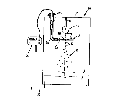
Figure 1 is a side view of an apparatus according to the invention,
Figure 2 is a perspective view of another apparatus according to the
invention,
Figure 3 is a plan view of the partly sectioned apparatus in Figure 2,
and
Figure 4 is a view in section through Figure 3 taken along line IV-IV
therein.
In an installation of which only part is shown for the sterile
encapsulation of microbial, vegetable and animal cells, disposed
horizontally in a reactor 10 above a hardening bath 12 and below a nozzle
16 which is suspended from a reactor cover 14 and at a spacing a in
relation to the nozzle 16 is a metal ring 18 having a central aperture 20
through which the nozzle axis A passes.
The metal ring 18 is secured by means of a radial holder 22 and a
tube 24 connected thereto in an insulating connection portion 26 in the
6
CA 02327716 2000-10-OS
reactor cover 14 and is connected through a line 28 disposed in the tube
26 to a high-voltage source 30.
An encapsulation mixture comprising an immobilisation matrix and
cells or substances is conveyed through the nozzle 16 in such a way that a
free laminar jet is produced. By virtue of a vibration being superimposed
on the free jet, the free jet is broken up into drops K of equal size. When
the fluid penetrates into an electrical field which is built up between the
metal ring 18 and the nozzle 16, a charge flux occurs in the direction of
the nozzle 16 so that the separated drops K: have an electrical charge,
being an electrostatic charge. That similar charge causes mutual repulsion
of the drops K.
That procedure results in two effects. On the one hand, the drops K
are stabilised in the axial direction, that is to say as soon as two drops K
come closer together by virtue of different speeds of fall, they are repelled
by the coulomb forces and they cannot come into contact with each other.
On the other hand, very small radial displacements are increased and the
single-strand 'chain of spheres is expanded to form a cone Q. Due to that
effect, coagulation of drops K is practically prevented and particles of
completely equal size are produced in the hardening bath 12. The charges
are removed by grounding of the hardening bath 12 at 32.
In an embodiment of a further installation for sterile encapsulation
of microbial, vegetable and animal cells, arranged above the hardening
bath 12 is a carrier plate 40 of a thickness b, which for example is
rectangular,
7
CA 02327716 2000-10-OS
with a depression 44 of a depth t which is formed in the center of its
surface 42; the depth t corresponds approximately to one third of the
plate thickness b.
The depression 44, as shown in Figure 4, is defined by a circular
peripheral wall 46 of a diameter d, and a bore 50 extends from the center
point of its bottom 48. The bore 50 opens at the other end in a cup-
shaped recess 52 of a diameter dl (approximately one third of d), which is
provided in the underneath surface 41 of the carrier plate 40 and in which
is carried a nozzle 54 connected to the bore 50. In addition, in the plane of
the bottom 48, a radial passage 56 leads to a lateral blind hole 58 for a
connecting portion 60.
Associated with the depression 44 is a pressure ring 66 which is
fixed on the plate surface 44 with the interposition of a diaphragm 62 and
a seal 64; the pressure ring 66, like also the seal 64, is provided with an
internal aperture 38 of a diameter d and the diaphragm 62 which carries a
disk magnet 70 extends over the depression 44. The diameter a of the
magnet 70 is somewhat greater than the diameter dl of the recess 52 for
the nozzle 54.
An electrical coil 74 is suspended from a holder 72 at a spacing with
respect to the disk magnet 70, centered with respect to the center line M
thereof. The disk magnet 70 and the coil 74 through which alternating
current flows form a vibrator; when alternating current is passed through
the coil 74 it is alternately positively and negatively magnetised. The
magnetic waves act on the subjacent disk magnet 70 and cause it to
vibrate together with the diaphragm 62.
AMENDED PAGE
CA 02327716 2000-10-OS
The introduction of that immobilisation mixture is effected by means of a
mechanical feed thrust or by air pressure into the pulsation chamber or
recess 44; from there the immobilisation mixture is urged through the
nozzle 54. The jet E which is produced there, shortly after issuing from the
nozzle 54, breaks up into spheres K1 of equal size, according to the
frequency of the superimposed vibration. At about 700 Hz, under optimum
conditions, 700 of the equal-sized spheres K1 are produced per second,
while the homogeneity of the sphere configuration is excellent by virtue of
the friction-less transmission. Measurements have shown that the power
required is less than 0.2 W.
In an embodiment not shown herein the permanent magnet 70 or
the coil 74 is provided directly at the nozzle 54 and the respective other
unit is associated therewith, forming an air gap.