Sélection de la langue

Search

Sommaire du brevet 2328009 

Énoncé de désistement de responsabilité concernant l'information provenant de tiers

Une partie des informations de ce site Web a été fournie par des sources externes. Le gouvernement du Canada n'assume aucune responsabilité concernant la précision, l'actualité ou la fiabilité des informations fournies par les sources externes. Les utilisateurs qui désirent employer cette information devraient consulter directement la source des informations. Le contenu fourni par les sources externes n'est pas assujetti aux exigences sur les langues officielles, la protection des renseignements personnels et l'accessibilité.

Disponibilité de l'Abrégé et des Revendications

L'apparition de différences dans le texte et l'image des Revendications et de l'Abrégé dépend du moment auquel le document est publié. Les textes des Revendications et de l'Abrégé sont affichés :

  • lorsque la demande peut être examinée par le public;
  • lorsque le brevet est émis (délivrance).
(12) Brevet: (11) CA 2328009
(54) Titre français: MECANISME DE FONCTIONNEMENT AVEC ENTRAINEMENT D'ENTREE AMELIOREE, POUR COMMUTATEURS ET COUPE-CIRCUITS
(54) Titre anglais: OPERATING MECHANISM WITH IMPROVED INPUT DRIVE ARRANGEMENT FOR SWITCHES AND CIRCUIT INTERRUPTERS
Statut: Durée expirée - au-delà du délai suivant l'octroi
Données bibliographiques
(51) Classification internationale des brevets (CIB):
  • H01H 71/10 (2006.01)
(72) Inventeurs :
  • FANTA, THOMAS O. (Etats-Unis d'Amérique)
  • WARD, ROBERT H. (Etats-Unis d'Amérique)
(73) Titulaires :
  • S&C ELECTRIC COMPANY
(71) Demandeurs :
  • S&C ELECTRIC COMPANY (Etats-Unis d'Amérique)
(74) Agent: OSLER, HOSKIN & HARCOURT LLP
(74) Co-agent:
(45) Délivré: 2009-05-12
(22) Date de dépôt: 2000-12-12
(41) Mise à la disponibilité du public: 2002-04-10
Requête d'examen: 2005-10-20
Licence disponible: S.O.
Cédé au domaine public: S.O.
(25) Langue des documents déposés: Anglais

Traité de coopération en matière de brevets (PCT): Non

(30) Données de priorité de la demande:
Numéro de la demande Pays / territoire Date
60/239,311 (Etats-Unis d'Amérique) 2000-10-10

Abrégés

Abrégé français

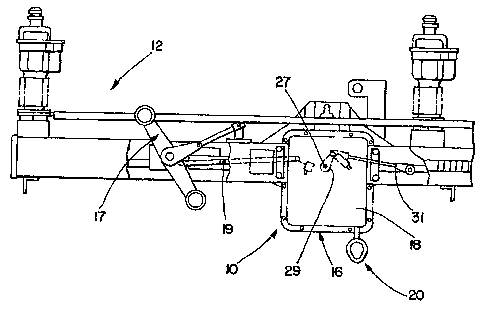
Le présent extrait concerne un mécanisme de fonctionnement compact pour commutateurs et coupe- circuits, qui apporte un entraînement d'entrée amélioré, et ce, plus particulièrement à un mécanisme de fonctionnement du type à action et coupure rapide pour les coupe-circuits électriques, c'est-à-dire les commutateurs interrupteurs de charge et les interrupteurs sur défaillance, l'entrée d'entraînement étant capable de fonctionnement soit motorisé soit manuel sans la nécessité d'aucun couplage/découplage ni sélection de mode.


Abrégé anglais

A compact operating mechanism for switches and circuit interrupters provides improved input drive arrangement and more particularly to a quick-make quick-break operating mechanism for electrical circuit interrupters, i.e. load-interrupter switches and fault interrupters, the drive input arrangement being capable of either power or manual operation without the necessity of any coupling/decoupling or mode selection.

Revendications

Note : Les revendications sont présentées dans la langue officielle dans laquelle elles ont été soumises.


The embodiments of the invention in which an exclusive property or privilege
is claimed
are defined as follows:
1. A drive input arrangement for an operating mechanism that includes a stored
energy mechanism and having an output coupled to an electrical switch to
operate the switch
between open and closed positions and a charging input to charge the stored
energy mechanism,
the drive input arrangement comprising:
power drive means responsive to an energy source for providing a power-driven
output;
a manual drive input;
a drive input for driving the stored energy mechanism of the operating
mechanism; and
drive coupling means coupled to said power-driven output and said manual drive
input for separately and independently coupling movement of said power-driven
output
and said manual drive input to the charging input without any coupling or
decoupling
being required, said drive-coupling means comprising a ratchet drive member
having
internal and external ratchet teeth and ratchet drive means for engaging each
of said
internal and external ratchet teeth and driving said ratchet drive member.
2. The drive arrangement of claim 1 wherein said power driven output and said
manual drive input are coupled to said ratchet drive means.
3. The drive arrangement of claim 2 wherein said ratchet drive means comprises
a
first drive pawl member operated by said manual drive input and a second drive
pawl member
operated by said power driven output.
4. The drive arrangement of claim 3 wherein said internal and external ratchet
teeth
are each arranged circumferentially about said ratchet drive member.
-6-

5. The drive arrangement of claim 4 wherein said ratchet drive member is
generally
circular and said internal and external ratchet teeth are arranged generally
concentrically with
respect to each other.
6. The drive arrangement of claim 4 wherein said drive-coupling means
comprises a
holding pawl member selectively engaging aid ratchet drive member to hold said
drive-coupling
means in a charged state.
7. The drive arrangement of claim 4 wherein said manual drive input comprises
a
manual operating member pivotally arranged about said ratchet drive member and
carrying said
first drive pawl so as to be pivotable with respect to said manual operating
member.
8. The drive arrangement of claim 4 wherein said first and second drive pawl
members are arranged to drive said ratchet member in the same direction.
9. The drive arrangement of claim 1 further comprising interlock means
responsive
to an interlock input for selectively disengaging said manual drive input from
being coupled to
the charging input.
10. The drive arrangement of claim 1 wherein said manual drive input comprises
a
manual operating member operable over a predetermined path and indexing means
responsive to
multiple operations of said manual operating member over the predetermined
path for coupling
movement to the charging input.
-7-

Description

Note : Les descriptions sont présentées dans la langue officielle dans laquelle elles ont été soumises.


CA 02328009 2000-12-12
SC-5331-C
OPERATING MECHANISM WITH IMPROVED INPUT DRIVE ARRANGEMENT FOR
SWITCHES AND CIRCUIT INTERRUPTERS
BACKGROUND OF THE INVENTION
1. Field of the Invention
The present invention relates generally to a compact operating mechanism for
switches
and circuit interrupters with improved input drive arrangement and more
particularly to a quick-
make quick-break operating mechanism for electrical circuit interrupters, i.e.
load-interrupter
switches and fault interrupters, the drive input arrangement being capable of
either power or
manual operation without the necessity of any coupling/decoupling or mode
selection.
2. Description of Related Art
Various operating mechanisms for electrical switches and circuit interrupters
provide
multiple operational states at an output corresponding to the desired
operational states of the
switch controlled by the mechanism. For example, U.S. Patent Nos. 5895987 and
6025657 are
directed to a power operator capable of manual or power operation without
decoupling.
Additionally, U.S. Patent No. 4146764 is directed to a spring-operated closing
mechanism for a
circuit breaker that does not require coupling/decoupling, the arrangement
including side-by-side
ratchet control plates with multiple rods passing therethrough that function
as pawls. A separate
opening spring is utilized for the opening function. Considering other
operating mechanisms, U.S.
Patent No. 3,563,102 discloses a quick-make quick-break mechanism for
operating a switch
between open and closed positions. Other operating mechanisms are shown in the
following U.S.
Patent Nos.: 3,845,433; 4,293,834; 5,140,117; and 5,224,590.
SUMMARY OF THE INVENTION
Accordingly, it is a principal object of the present invention to provide a
compact
operating mechanism for switches and circuit interrupters with improved input
drive arrangement
and more particularly to a quick-make quick-break operating mechanism for
electrical circuit
interrupters, i.e. load-interrupter switches and fault interrupters, the drive
input arrangement being

CA 02328009 2000-12-12
SC-5331-C
capable of either power or manual operation without the necessity of any
coupling/decoupling or
mode selection.
It is another object of the present invention to provide a compact operating
mechanism
that incorporates manual and power drive inputs without the necessity of
coupling/decoupling
functions.
These and other objects of the present invention are achieved by a compact
operating
mechanism for switches and circuit interrupters with improved input drive
arrangement and more
particularly to a quick-make quick-break operating mechanism for electrical
circuit interrupters,
i.e. load-interrupter switches and fault interrupters, the drive input
arrangement being capable of
either power or manual operation without the necessity of any
coupling/decoupling or mode
selection.
BRIEF DESCRIPTION OF THE DRAWING
The invention, both as to its organization and method of operation, together
with further
objects and advantages thereof, will best be understood by reference to the
specification taken in
conjunction with the accompanying drawing in which:
FIG. 1 is a front elevational view of a switch incorporating the operating
mechanism in
accordance with the principles of the present invention;
FIGS. 2 and 3 are front elevational views of the operating mechanism of FIG. 1
with parts
cut away and removed for clarity;
FIG. 4 is an enlarged elevational view of the operating mechanism of FIGS. 2
and 3 and
illustrating a different operative position;
FIG. 5 is an elevational view of the ratchet wheel of the operating mechanism
of FIGS. 2-
4; and
FIGS. 6 and 7 are partial views on an enlarged scale of portions of the
operating
mechanism of FIGS. 2-4 and illustrating operating control features thereof.
-2-

CA 02328009 2000-12-12
SC-5331-C
DETAILED DESCRIPTION
Referring now to FIG. 1, an operating mechanism 10 of the present invention is
of the
quick-make, quick-break variety and is useful to provide operation of a
circuit interrupter, e.g. in
a specific application, a group-operated switch 12 as shown in FIG. 1 and in
U.S. Patent Nos.
4,938,792, 5,075,521, 5,091,616 and 5,103,111. In response to power supply
connections and
control signals, the operating mechanism 10 charges a stored energy mechanism
and controls
operation thereof between an open position and a closed position.
Additionally, the operating
mechanism 10 in response to a manual input at 20, operates between open and
closed positions.
The operating mechanism 10 includes a housing 16 having a removable cover
portion 18.
Referring now additionally to FIGS. 2-5, the operating mechanism 10 includes a
stored-energy
mechanism 24, that is rotated via a drive input 26. The operating mechanism 10
via a drive
output lever 29 at an output at 27 operates the drive linkage of the switch,
e.g. at 31 in FIG. 1
and at 93, 95 of FIG. 5 in U.S. Patent No. 5,091,616. The stored energy
mechanism 24 is of the
general type shown in U.S. Patent Nos. 3,563,102 and 5,075,521. The drive
input 26 is driven
through a linkage 28 which in turn is connected to be driven at 30 from a
drive arrangement 32.
The drive arrangement at 32 includes a ratchet wheel 34 that fixedly carries a
drive lever 36, a
distal end 38 of the drive lever 36 including a pin 40 to provide connection
to the linkage 28 at
30. The ratchet wheel 34 is rotatably carried about an output shaft 50 of a
motor drive 52. As
seen in FIG. 5, the ratchet whee134 is driven by a pair of pawls 42, 44
mounted within a hub 46
carried within the ratchet wheel 34 having internal ratchet teeth 48, the hub
46 being keyed to the
output shaft 50 and being spring-biased at 54 in an outward direction. For
manual operation, a
manual drive lever 60 is provided that includes a manual drive pawl 62
pivotally carried by the
manual drive lever 60, the manual drive paw162 also being characterized as an
indexing pawl
since multiple strokes of the manual drive lever 60 are required as will be
explained in detail
hereinafter. The manual drive lever 60 is pivotally mounted at 50 and includes
a bumper at 64.
The ratchet wheel 34 includes external ratchet teeth 37 arranged about the
outer periphery 35 of
the ratchet wheel 34. The drive pawls 42, 44 are overdriven during the manual
driving of the
ratchet wheel 34 via the indexing pawl 62 thereby not backdriving the motor
drive 52.
Correspondingly, during power operation, the manual drive paw162 is overdriven
as the ratchet
-3-

CA 02328009 2000-12-12
SC-5331-C
wheel 34 is rotated by the pawls 42, 44. A holding pawl 70 is provided to
prevent backdriving of
the stored energy mechanism 24 and the ratchet wheel 34.
In normal operation where a power supply is present, the operating mechanism
10 charges
the stored energy mechanism 24 to a predetermined pre-charged point prior to
an opening or
closing operation such that the operating mechanism 10 is always ready for a
fast open or close
operation upon command. When it is desired to change the state of the
operating mechanism 10,
e.g. from open to closed or closed to open, the operating mechanism 10 is
controlled via the
output shaft 50 of the motor drive 52 to drive the stored-energy mechanism 24
beyond the pre-
charged state and past the release point of the stored-energy mechanism 24
thereby causing
operation. The motor drive 52 immediately recharges the stored-energy
mechanism 24 to the pre-
charged state for the next operation.
When a power supply is not present, manual operation is available via the
manual input at
to operate the operating mechanism 10 to change the state of the driven
switch. Specifically, a
manually operable arrangement 100 including a pull ring 102 that is
reciprocated between the
15 positions of FIGS. 2 and 3 a number of times to charge and operate the
stored-energy mechanism
24. The manually operable arrangement 100 includes a pull rod 104 biased by a
spring 106 with
the spring being retained between the cover 18 and the pull rod 104 and being
compressed upon
each downward stroke of the pull ring 102. Thus, the pull rod is returned
under the bias of the
spring 106. The pull rod 104 is connected at 108 to pivot the manual drive
lever 60.
20 For normal operation where a power supply is present and considering now
the
arrangement of the operating mechanism 10 to charge the stored energy
mechanism 24 to the
predetermined pre-charged point and referring specifically now to FIGS. 4, 6
and 7, two control
grooves 120, 122 arranged on the periphery of an outside hub 39 of the ratchet
wheel 34
cooperate with a limit switch assembly 124. The limit switch 124 is arranged
to control power to
the motor drive 52. The limit switch assembly 124 includes an intermediate
lever 126 that is
biased toward the ratchet wheel 34 via a spring 128 and that is positioned to
ride on the outside
hub 39 of the ratchet whee134. When the motor drive 52 has charged the stored
energy
mechanism 24 to the pre-charged state, the intermediate lever 126 moves into
one of the control
grooves 120, 122 actuating the limit switch 124 which turns off the motor
drive 52 as illustrated
-4-

CA 02328009 2000-12-12
SC-5331-C
in FIG. 7. Thus, the operating mechanism 10 is maintained in the pre-charged
position for either
opening or closing upon command. The positions illustrated in FIG. 6 depicts
the position of the
intermediate lever 126 just prior to actuation of the limit switch 124 before
reaching the pre-
charged position. The expanse and shape of the control grooves 120, 122 permit
back driving
and coasting of the motor drive 52 without deactuating the limit switch 124.
Considering now an interlock feature of the operating mechanism 10 to prevent
manual
operation when a disconnect switch of the group-operated switch 12 is in an
open position, a
movable cam surface 130 is provided to lift the manual indexing pawl 62 via
contact thereof away
from engagement with the ratchet wheel 34 as shown in FIG. 4. Thus, operation
of the manual
drive lever 60 will neither charge nor trip the operating mechanism 10.
Movement of the
disconnect operating linkage 17 (FIG. 1) is communicated to the operating
mechanism 10 via a
connecting member 19.
While there have been illustrated and described various embodiments of the
present
invention, it will be apparent that various changes and modifications will
occur to those skilled in
the art. Accordingly, it is intended in the appended claims to cover all such
changes and
modifications that fall within the true spirit and scope of the present
invention.
-5-

Dessin représentatif
Une figure unique qui représente un dessin illustrant l'invention.
États administratifs

2024-08-01 : Dans le cadre de la transition vers les Brevets de nouvelle génération (BNG), la base de données sur les brevets canadiens (BDBC) contient désormais un Historique d'événement plus détaillé, qui reproduit le Journal des événements de notre nouvelle solution interne.

Veuillez noter que les événements débutant par « Inactive : » se réfèrent à des événements qui ne sont plus utilisés dans notre nouvelle solution interne.

Pour une meilleure compréhension de l'état de la demande ou brevet qui figure sur cette page, la rubrique Mise en garde , et les descriptions de Brevet , Historique d'événement , Taxes périodiques et Historique des paiements devraient être consultées.

Historique d'événement

Description Date
Inactive : Périmé (brevet - nouvelle loi) 2020-12-14
Représentant commun nommé 2019-10-30
Accordé par délivrance 2009-05-12
Inactive : Page couverture publiée 2009-05-11
Inactive : Taxe finale reçue 2009-02-23
Préoctroi 2009-02-23
Exigences de modification après acceptation - jugée conforme 2009-02-09
Lettre envoyée 2009-02-09
Modification après acceptation reçue 2009-02-02
Un avis d'acceptation est envoyé 2009-01-13
Lettre envoyée 2009-01-13
Un avis d'acceptation est envoyé 2009-01-13
Inactive : Approuvée aux fins d'acceptation (AFA) 2008-08-26
Modification reçue - modification volontaire 2008-01-31
Inactive : Dem. de l'examinateur par.30(2) Règles 2007-08-03
Lettre envoyée 2005-11-02
Requête d'examen reçue 2005-10-20
Exigences pour une requête d'examen - jugée conforme 2005-10-20
Toutes les exigences pour l'examen - jugée conforme 2005-10-20
Inactive : Page couverture publiée 2002-04-12
Demande publiée (accessible au public) 2002-04-10
Lettre envoyée 2002-02-18
Inactive : Transfert individuel 2002-01-10
Inactive : CIB en 1re position 2001-02-06
Inactive : Lettre de courtoisie - Preuve 2001-01-23
Inactive : Certificat de dépôt - Sans RE (Anglais) 2001-01-19
Demande reçue - nationale ordinaire 2001-01-18

Historique d'abandonnement

Il n'y a pas d'historique d'abandonnement

Taxes périodiques

Le dernier paiement a été reçu le 2008-11-21

Avis : Si le paiement en totalité n'a pas été reçu au plus tard à la date indiquée, une taxe supplémentaire peut être imposée, soit une des taxes suivantes :

  • taxe de rétablissement ;
  • taxe pour paiement en souffrance ; ou
  • taxe additionnelle pour le renversement d'une péremption réputée.

Les taxes sur les brevets sont ajustées au 1er janvier de chaque année. Les montants ci-dessus sont les montants actuels s'ils sont reçus au plus tard le 31 décembre de l'année en cours.
Veuillez vous référer à la page web des taxes sur les brevets de l'OPIC pour voir tous les montants actuels des taxes.

Titulaires au dossier

Les titulaires actuels et antérieures au dossier sont affichés en ordre alphabétique.

Titulaires actuels au dossier
S&C ELECTRIC COMPANY
Titulaires antérieures au dossier
ROBERT H. WARD
THOMAS O. FANTA
Les propriétaires antérieurs qui ne figurent pas dans la liste des « Propriétaires au dossier » apparaîtront dans d'autres documents au dossier.
Documents

Pour visionner les fichiers sélectionnés, entrer le code reCAPTCHA :


Pour visualiser une image, cliquer sur un lien dans la colonne description du document. Pour télécharger l'image (les images), cliquer l'une ou plusieurs cases à cocher dans la première colonne et ensuite cliquer sur le bouton "Télécharger sélection en format PDF (archive Zip)" ou le bouton "Télécharger sélection (en un fichier PDF fusionné)".

Liste des documents de brevet publiés et non publiés sur la BDBC .

Si vous avez des difficultés à accéder au contenu, veuillez communiquer avec le Centre de services à la clientèle au 1-866-997-1936, ou envoyer un courriel au Centre de service à la clientèle de l'OPIC.


Description du
Document 
Date
(aaaa-mm-jj) 
Nombre de pages   Taille de l'image (Ko) 
Dessin représentatif 2002-03-12 1 13
Description 2000-12-11 5 253
Revendications 2000-12-11 3 92
Abrégé 2000-12-11 1 13
Dessins 2000-12-11 5 169
Revendications 2008-01-30 2 71
Dessins 2009-02-01 6 158
Dessin représentatif 2009-04-16 1 14
Certificat de dépôt (anglais) 2001-01-18 1 164
Demande de preuve ou de transfert manquant 2001-12-12 1 109
Courtoisie - Certificat d'enregistrement (document(s) connexe(s)) 2002-02-17 1 113
Rappel de taxe de maintien due 2002-08-12 1 109
Rappel - requête d'examen 2005-08-14 1 116
Accusé de réception de la requête d'examen 2005-11-01 1 176
Avis du commissaire - Demande jugée acceptable 2009-01-12 1 163
Correspondance 2001-01-18 1 25
Correspondance 2009-02-22 1 44