Note : Les descriptions sont présentées dans la langue officielle dans laquelle elles ont été soumises.
CA 02328371 2000-12-13
MULTI-POSITION POINT OF USE ELECTRIC WATER HEATER
BACKGROUND OF THE INVENTION
The present invention generally relates to apparatus for heating liquid and,
in a
preferred embodiment thereof, more particularly provides a specially designed
multi-
position point of use electric water heater.
Point-of use electric water heaters are relatively small capacity water
heaters
which are typically capable of storing, for on-demand supply, heated water
quantities in
the representative range of from about two gallons to about thirty gallons. A
small water
heater of this type is customarily used to serve a single hot water-using
plumbing fixture,
such as a sink, or only a few plumbing fixtures, and is operatively positioned
relatively
close to the fixtures) that it serves - thus the designation "point-of use"
water heater -
as opposed to being located remotely from the fixtures) which it serves.
The compact size of the typical point-of use electric water permits it to be
conveniently tucked away in a concealed space adjacent its associated plumbing
fixtures) such as, for example, in the cabinet area beneath a sink served by
the water
heater, in a nearby closet, or above the ceiling area near the fixture(s).
Alternatively, the
point of use water heater may be mounted in an exposed area near the fixtures)
such as
on a wall or ceiling.
To accommodate the space available for the point of use electric water heater,
it
may be necessary to position the water heater in one of a variety of manners
including
supporting it in ( 1 ) a vertical orientation on the floor or on a wall, with
the nominal top
end of the water heater facing upwardly, (2) an inverted vertical orientation
on a wall,
with the top end of the water heater facing downwardly, or (3) a horizontal
orientation
on a wall, ceiling or other horizontal support structure, with the top end of
the water
CA 02328371 2000-12-13
heater facing horizontally.
As conventionally manufactured, a point-of use electric water heater must be
built
in several separate configurations to accommodate these differing installation
orientations
without undesirably degrading the water heating efficiency of the unit or
presenting
installation difficulties of various types. The need to provide these
different
configurations, of course, undesirably adds to the manufacturing cost of a
given water
heater product line and correspondingly limits the installation and
performance flexibility
of a given water heater configuration.
From the foregoing it can be readily seen that a need exists for a point-of
use
electric water heater that eliminates, or at least substantially reduces,
these problems,
limitations and disadvantages typically associated with conventionally
configured point-
of use electric water heaters. It is to this need that the present invention
is directed.
SUMMARY OF THE INVENTION
In carrying out principles of the present invention, in accordance with a
preferred
embodiment thereof, a point of use electric water heater is provided with a
unique
configuration that permits it to be mounted in a selectively variable one of
several
horizontal and vertical orientations without having to substantially vary the
configuration
of the water heater to accommodate variation in its mounting orientation, or
reducing its
water heating efficiency to an unacceptable extent. This desirably permits the
point of
use water heater to be manufactured in a single configuration useable in each
of its
potential mounting orientations.
In its preferred embodiment, the water heater comprises an insulated tank
structure adapted to hold a quantity of water, the insulated tank structure
having opposite
first and second end portions spaced apart along a central axis, the insulated
tank
structure further having front and rear side portions disposed on opposite
sides of a
reference plane containing the central axis. Water inlet and outlet tubes
longitudinally
extend parallel to the central axis and into the interior of the rear side
portion of the
insulated tank structure through its first end portion. Additionally, an
elongated electric
-2-
CA 02328371 2000-12-13
resistance type immersion heating structure longitudinally extends through the
tank
interior at least generally parallel to the central axis, the heating
structure being operative
to heat water disposed within the insulated tank structure.
A first opening is disposed in the front side portion of the insulated tank
structure
at its first end portion and extends into the interior of the insulated tank
structure. A
second opening is disposed in the front side portion of the insulated tank
structure at its
second end portion and extends into the interior of the insulated tank
structure. A
temperature and/or pressure relief structure is removably secured to one of
the first and
second opening and is removably securable to the other of the first and second
openings.
Additionally, a drain valve structure is removably secured to the other of the
first and
second openings and is removably securable to the aforementioned one of the
first and
second openings.
Representatively, the water heater has first and second reference lines
extending
through its first end portion, with the first reference line being rearwardly
offset from the
reference plane and transverse to the central axis, and the second reference
line being
forwardly offset from the reference plane and transverse to the central axis.
Preferably,
the inlet and outlet tubes are spaced apart along the first reference line,
and the heating
structure and the first opening are spaced apart along the second reference
line. An
electrical junction box is mounted on the first end and is preferably
rearwardly offset
from the inlet and outlet tubes.
According to another feature of the invention, the insulated tank structure
has
secured thereto a mounting structure which facilitates the vertical and
horizontal
mounting of the water heater on an adjacent support structure. Preferably, the
mounting
structure includes an axially spaced pair of elongated mounting bracket
members which
longitudinally extend transversely to the central axis and have longitudinally
central
portions secured to the rear side of the insulated tank structure at axially
spaced locations
on the rear side thereof. Projecting outwardly from these longitudinally
central bracket
portions are opposite end portions with side edges through which generally L-
shaped
mounting slots extend, the slots being adapted to receive outwardly projecting
portions
-3-
CA 02328371 2000-12-13
of support members secured to the support structure on which the water heater
is to be
mounted vertically or horizontally.
In accordance with another aspect of the invention, the electric resistance
type
immersion heating structure representatively includes a body portion which is
securable
to the tank at an opening therein, and first and second elongated electrical
resistance type
heating elements which longitudinally project from the inner side of the body
portion
axially into the interior of the tank, one of the first and second heating
elements being
substantially longer than the other heating element. A temperature control
structure is
operative to control the operation of the first and second heating elements
and
representatively includes a heating tube longitudinally projecting outwardly
from the
inner side of the body portion parallel to the first and second heating
elements. First and
second thermistors are disposed within the tube, in an axially spaced
relationship therein,
and are respectively associated with the first and second heating elements.
BRIEF DESCRIPTION OF THE DRAWINGS
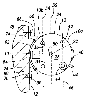
FIG. 1 is a simplified top end view of a specially designed multi-position
point
of use electric water heater embodying principles of the present invention,
with the water
heater representatively being horizontally mounted on a wall;
FIG. 2 is a front side elevational view of the horizontally supported water
heater;
FIG. 3 is a front side elevational view of the water heater in a floor-
supported
vertical orientation;
FIG. 4 is a front side elevational view of the water heater in a wall-
supported
inverted vertical orientation;
FIG. 5 is an enlarged scale perspective view of a specially designed support
bracket used to mount the water heater on a wall or ceiling;
FIG. 6 is an enlarged scale perspective detail view of the end portion of the
support bracket generally within the dashed circle area "6" in FIG. 5;
FIG. 7 is an enlarged scale perspective view of a dual element electrical
resistance
type immersion heating structure used in the water heater; and
-4-
CA 02328371 2000-12-13
FIG. 8 is an enlarged scale, simplified and longitudinally foreshortened side
elevational view of an alternate embodiment of he immersion heating structure
shown
in FIG. 7.
DETAILED DESCRIPTION
Illustrated in simplified form in FIGS. 1-4 is a specially designed multi-
position
point of use electric water heater 10 that embodies principles of the present
invention.
According to a key aspect of the invention, the water heater 10, as later
described herein,
may be (1) horizontally mounted on a wall 12 (see FIGS. 1 and 2) or on or
above a
ceiling (not shown), (2) vertically supported on a floor 14 (see FIG. 3) or
the wall 12, or
(3) vertically mounted in an inverted orientation on the wall 12. This multi-
position
orientation of the same water heater 10 may be achieved without substantial
modification
thereof, and without unduly degrading its water heating performance. This
advantageously permits a point of use electric water heater to be manufactured
in a single
configuration without the previous necessity of building it in several
different
configurations to enable it to be operatively supported in the various
orientations
representatively illustrated in FIGS. 1-4.
Still referring to FIGS. 1-4, the illustrated mufti-position point of use
electric
water heater 10 includes a representatively cylindrical metal water storage
tank 16
adapted to hold a quantity of heated water deliverable on demand to one or
more hot
water-using fixtures (not illustrated) with which the water heater 10 is
adjacent and
operatively associated. Tank 16 has upper and lower ends 18,20 which are
spaced apart
along a central axis 22 of the water heater 10. A generally conventional metal-
jacketed
insulation structure 24 outwardly envelopes the tank 16 and has circular upper
and lower
ends 26 and 28. The lower jacket structure end 28 is tied to the lower end 20
of the tank
16 by a suitable bracket member 30.
For purposes of the description of various positional and configurational
aspects
of the water heater 10, a reference plane 32 has been shown in FIG. 1.
Reference plane
32 extends parallel to and contains the central axis 22, and divides the water
heater 10
-5-
CA 02328371 2000-12-13
into circumferentially equal front and rear side portions 10a and 10b. The
front side
portion 10a of the water heater 10 is shown in FIGS. 2-4, with a portion of
the wall 12
(positioned rearwardly of the water heater 10) being shown for reference
purposes.
Referring now to FIGS. 1 and 2, water heater 10 includes inlet and outlet
tubes
34,36 that longitudinally extend into the interior of the tank 16, parallel to
the central
water heater axis 22, through the top end 26 of the water heater 10. The tubes
34,36 have
exposed outer end portions 34a,36a respectively connectable to water inlet and
outlet
pipes (not shown). As best illustrated in FIG. 1, tubes~34,36 are disposed in
the rear side
portion l Ob of the water heater 10 and are spaced apart along a dashed
reference line 38
(see FIG. 1) which extends chordwise along the top side 26 of the water heater
10, and
is rearwardly offset from and parallel to the reference plane 32. An
electrical junction
box 40 is mounted on the top end 26 of the water heater, generally centered
between the
inlet and outlet tubes 34 and 36, and rearwardly offset from the reference
line 38.
Extending downwardly through the top end 26 of the water heater 10 into the
interior of the tank 16 is a conventional temperature and/or pressure relief
fitting 42
which is forwardly offset from the reference plane 32, generally aligned with
the outlet
tube 36, and removably secured to the tank 16 at an opening 42a therein. An
elongated
electric resistance type immersion heater structure 44 longitudinally extends
downwardly
through the top end of the tank 16 into its interior, is aligned with the
inlet tube 34, and
is spaced apart from the temperature and pressure relief fitting 42 along a
dashed
reference line 46 (see FIG. 11 that is forwardly offset from and parallel to
the reference
plane 32. The immersion heater structure 44 is removably secured to the tank
16 and is
operatively controlled by a thermostat 48 which senses the temperature of the
water
within the tank 16 and is positioned on a lower front side portion of the
water heater 10
as schematically indicated in FIG. 2. Alternatively, heater structure 44 could
enter the
tank 16 through a side thereof, have a suitably bent configuration, and still
longitudinally
extend generally parallel to the central axis 22.
Cathodic protection is provided for the water heater 10 by means of a
conventional elongated anode structure 50 that longitudinally extends
centrally through
-6-
CA 02328371 2003-07-14
a central top end portion of the tank 16 inter its interior. .~'1t a lower
front end portion of
the water heater 10 is a drain. calve stru~tcrr~; :i2 ~.vlri.c,lr is removably
secured to the tank
16, at an opening 52a tyerein, and is communicated with tlae interior of the
tank 16.
As illustrated in FIG. ; , the elongated electric; resist:arrce type immersion
heater
structure 44 which :longitudinally extends into the inter~i«r of the tank in a
direction
parallel to the central axis 22 is representatively a dual element unit having
a hexagonal
head portion 54 from one side c:,af which a threaded cylindrical body 56
outwardly
projects, the body 56 being rernc>vably thr°eadeci into a corresponding
opening in the
upper tank end. Longitudina115~ extending outwardly li orn the outer end of
~:he cylindrical
body 56 are elongated first and second generally 1.?-shaped first and seccand
resistance
type immersion heating elements 58 Grrad 60, the second element 60 being
substantially
shorter than the first heating element 5 ~ 1-ieatc,r structure 44 'is
removable trorn the water
heater 10 through its upper end 26. t=~lternativ~°1~~, the heater
structure 44 could be a
single element unit if desired.
With reference now to k~ iGS. 1, ;?, S and 6, thre mufti-position point of use
electric
water heater 10 also includes a pair ol° specially designed mounting
brackets 62 which
facilitate the mounting of the water heater 10 i~:3 several subsequently
described
orientations. Each mounting bracket fit is an elongated strip of metal hsrving
a curved
longitudinally central section 64 and ;~tr~.iglrt opposite oi.rter en d
portions 66 connected
to the ends of the curved section fi4 by tran.sverse,aoinir:rg, portions 68.
Formed in each
of the end portions 6ti is a generally L-shaped slot 7(I ( see l~ ICJ. 6)
having an entry portion
70a extending inwardly through a side edge 'T"7 c>f the end portion 66., and a
transverse
portion 70b extending parallel to the edge '7?. "I°11e, c:ur ed central
portions 64 of the
brackets 62 are remcwably secured to circ;urnlerentiazlly aligned top and
bottom arcuate
portions of the rear side 10b ol'the water heater by threaded fasteners 74
(see FIG. 1).
The mufti-position point of use eater heater 1 t) as shown in F nJS. 1 and 2
is
horizontally mounted on the wall 12 1?y first aecurin~; on the wall suitably
spaced apart
support members 76 which prc~jeca c>u wa:rdly tlmreficsm. Water heater 10 is
then
mounted on the wall 12, with the rear side portion 11)b facing the wall 10 and
the drain
-;_
CA 02328371 2003-07-14
valve 52 oriented on the bottom side ohthe laorizantal water heater 10, by
simply moving
the braclcet end slot portions 70a (see F1(). 6 ) horizontally parallel to the
wall 12 and over
the outwardly projecting porticrrls of tlae support merrabers 76 (which
il.lusgratively have
laterally enlarged outer end head pc.~r'tiorr:~), arzcl then mo~°ing
the water heater 10
S downwardly to cause thcoutwtrrdly projecting positions a-of tlne support
members 76 to
move into the bracket end slot portions 7()b. l~;xt~:rra.~tl piping and
electrical connections
are then made to the horizontally rrzounted water heslter 10.
With the water heater 1l) horvizc>ntally raaounted on the wall 12 in this
manner, the
water inlet and outlet tubes 31,36 and th a electrical jccnc;tion box 40 are
conveniently
positioned adjacent the wall 12, to facilitate external piping anti electrical
c~ormections to
the mounted water heater. Additiconally, the elect rical innmersion heater
;~tzucture 44 is
positioned at an underside portion ol~ the :hc>rizc>nt:a.lly oriented wager-
heater 10 for
efficient heating of water stored in the tank 1(~, and the drain valve
structure 52 is
positioned on an underside portion cal' they hr~rizc>nt'.ally oriented wai:er
heater 10 for
1S efficient draining of the tank 16 shovzld the xteed arise. Further, the
ther~rnostat 48 is
conveniently exposed on the front side c:>1° the mounted water heater
for ready access and
adjustment.
As previously mentioned herein, due tc> its urziqtre configuration, the same
point
of use water heater 10 may also be hositicmed irr -:several other orientations
without
appreciably modifying the water header. 'I°his advantageously avoids
the previous
necessity of manufacturing the water heater in a ~-arie~ty of separ°ate
configurations in
order to accommodate several desired rrzounting orientations.
For example, the water heater 1 i) in its 1i 1t1. 1 borizon al wall-mounted
orientation
may alternatively mounted in a hori2.ocltal orierztatiorz o~ a ceiling (not
shown) or on
structure above the ceiling by simply rotating the water 10 ninety degrees in
a clockwise
direction from its FIt;~. 1 orient:atiorr, opi;rative~ly cc~r~ne4.ting the
opposite ends 66 of the
brackets 62 to horizonta115- oriented support member secured to the ceili~ g
or structure
above the ceiling, and switching t:lle l~asitions of thc: irrlc~t tube 34 and
t:he temperature
and/or pressure relief structure =12..
-- _ - -~- _ -.
CA 02328371 2000-12-13
Additionally, as shown in FIG. 3, the water heater may simply be placed,
bottom
end 28 down, on the floor 28 with the rear side 1 Ob of the water heater 10
facing the wall
12. Further support for the vertically floor-mounted water heater 10 may be
achieved by
simply connecting the outer ends 66 of the brackets 62 to the wall 12. In this
vertically
floor-mounted orientation of the water heater 10, the inlet and outlet tube
ends 34a,36a
and the junction box 4U are conveniently disposed adjacent the wall 12, and
the drain
valve structure 52 is positioned at a bottom end portion of the water heater
10 to facilitate
drainage of its tank portion 16 if necessary. It will readily appreciated
that, if desired, the
vertically oriented water heater 10 shown in FIG. 3 may alternatively be wall
mounted,
with the bottom water heater end 28 spaced upwardly apart from the floor 14,
simply by
using the brackets 62 to mount the water heater 10 in a vertical orientation
on the wall
12.
It is important to note at this point that to switch the water heater 10 from
its
horizontal orientation shown in FIGS. 1 and 2 to its vertical orientation
shown in FIG.
3 it is not necessary to modify the water heater 10 in any manner. However,
depending
on the tank height of the water heater 10 it may be desirable to substitute a
somewhat
longer immersion heater structure 44a for the previously described immersion
heater
structure 44 to introduce water heating at a lower location in the tank 16.
Using the same brackets 62 with their L-shaped end portion mounting slots 70
(see FIG. 6) the water heater l 0 may be inverted and vertically supported on
the wall 12,
bottom end 28 up and with the rear side portion of the water heater 10 facing
the wall 12,
as indicated in FIG. 4. In this orientation of the water heater 10, the
brackets 62 are
secured to the support members projecting outwardly from the wall by
downwardly
moving the bracket end slot portions 70a over the support members, and then
moving the
water heater 10 leftwardly as viewed in FIG. 4 to cause the wall support
members to enter
the horizontal bracket end slot portions 70a. As can be seen by comparing the
wall
installations of the water heater in FIGS. 2 and 4, the L-shaped bracket end
slots 70
conveniently adapt the water heater 10 to either vertical or horizontal
mounting on the
wall 12 without altering the support structure for the water heater.
-9-
CA 02328371 2000-12-13
From the standpoint of reconfiguring the water heater 10 when it is changed
from
its FIG. 2 horizontal orientation or its FIG. 3 vertical orientation to its
FIG. 4 inverted
vertical orientation, all that is necessary is to switch the locations of the
temperature and
pressure relief structure 42 and the drain valve structure 52 and reconnect
these structures
to the tank 16. In other words, the pressure relief structure 42 is
repositioned to and
removably connected at the tank opening 52a, and the drain valve structure 52
is
repositioned to and removably connected at the tank opening 42a. As can be
seen in FIG.
4, this places the temperature and pressure relief structure 42 in an upper
left location of
the front side portion 1 Oa of the water heater 10, and places the drain valve
structure 52
on the inverted top end 26 end of the water heater 10.
Illustrated in FIG. 8 is an alternate embodiment 44b of the previously
described
electric resistance type immersion heater structure 44. For ease in comparison
between
the heater structures 44 and 44b, elements in the heater structure 44b similar
to those in
the heater structure 44 have been given identical reference numerals having
the subscripts
"b".
Heater structure 44b includes a hexagonal head portion 54b from one side of
which an externally threaded cylindrical body portion 56 outwardly projects.
Extending
outwardly from the right side of the body portion 56b as viewed in FIG. 8 are
an
elongated, generally U-shaped first electric resistance type immersion heating
element
58b, and a somewhat shorter elongated, generally U-shaped second electric
resistance
type immersion heating element 60b. Heating elements 58b,60b are electrically
coupled
to terminals 78 on the left side of the hexagonal head portion 54b. In turn,
the terminals
78 are coupled to a suitable control panel 80 via electrical leads 82.
Incorporated in the heater structure 44b is an integral temperature sensing
structure 84 which replaces the thermostat 48 in the water heater 10. The
temperature
sensing structure 84 includes a closed heat sensing tube 86 longitudinally
extending
outwardly from the right side of the cylindrical body portion 56b. Two
temperature
sensing thermistors 88 and 90 are carried within the tube 86 in a
longitudinally spaced
relationship therein, the therrnistor 88 being associated with the heating
element 58b, and
-10-
CA 02328371 2000-12-13
the thermistor 90 being associated with the heating element 60b. Thermistors
88,90 are
respectively connected to terminals 92,94 on the left side of the hexagonal
head portion
54b by electrical leads 96,98 extending through the interior of the tube 86.
Terminals 92
and 94, in turn, are connected to the control panel 80 by electrical leads 100
and 102.
During operation of the water heater 10, the control panel 80 uses the water
temperature
sensed by the thermistor 88 to control the operation of the immersion heating
element
58a, and uses the water temperature sensed by the thermistor 90 to control the
operation
of the immersion heating element 60b.
The foregoing detailed description is to be clearly understood as being given
by
way of illustration and example, the spirit and scope of the present invention
being
limited solely by the appended claims.
-11-