Une partie des informations de ce site Web a été fournie par des sources externes. Le gouvernement du Canada n'assume aucune responsabilité concernant la précision, l'actualité ou la fiabilité des informations fournies par les sources externes. Les utilisateurs qui désirent employer cette information devraient consulter directement la source des informations. Le contenu fourni par les sources externes n'est pas assujetti aux exigences sur les langues officielles, la protection des renseignements personnels et l'accessibilité.
L'apparition de différences dans le texte et l'image des Revendications et de l'Abrégé dépend du moment auquel le document est publié. Les textes des Revendications et de l'Abrégé sont affichés :
| (12) Brevet: | (11) CA 2328538 |
|---|---|
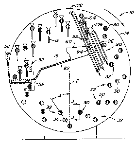
| (54) Titre français: | DISPOSITIF DE TRI ET D'ALIGNEMENT DES PIECES |
| (54) Titre anglais: | PART SORTING AND ALIGNING APPARATUS |
| Statut: | Périmé et au-delà du délai pour l’annulation |
| (51) Classification internationale des brevets (CIB): |
|
|---|---|
| (72) Inventeurs : |
|
| (73) Titulaires : |
|
| (71) Demandeurs : |
|
| (74) Agent: | BORDEN LADNER GERVAIS LLP |
| (74) Co-agent: | |
| (45) Délivré: | 2005-03-22 |
| (22) Date de dépôt: | 2000-12-13 |
| (41) Mise à la disponibilité du public: | 2001-11-12 |
| Requête d'examen: | 2000-12-13 |
| Licence disponible: | S.O. |
| Cédé au domaine public: | S.O. |
| (25) Langue des documents déposés: | Anglais |
| Traité de coopération en matière de brevets (PCT): | Non |
|---|
| (30) Données de priorité de la demande: | ||||||
|---|---|---|---|---|---|---|
|
A part sorting and aligning apparatus for picks parts out of a hopper, aligns
the parts
and conveys them to another location. The apparatus includes a tilted rotary
wheel next to
the hopper. Multiple arrays of hooks or pickup members are mounted for
rotation on the
wheel. The bottom of the hopper has a sliding plate which has slots through
which the
hooks travel as the hooks move upwardly into and through the hopper. Each
pickup
member has a weight bar which hangs from the pickup member. As the wheel
rotates, the
hooks engage and pick up parts as the hooks move upwardly through the hopper.
The
weight bar maintains a desired orientation of the hooks and the parts as the
wheel rotates.
Pair of rails pick the parts off of the hooks, so that the parts can be
transferred to another
location.
Note : Les revendications sont présentées dans la langue officielle dans laquelle elles ont été soumises.
Note : Les descriptions sont présentées dans la langue officielle dans laquelle elles ont été soumises.
2024-08-01 : Dans le cadre de la transition vers les Brevets de nouvelle génération (BNG), la base de données sur les brevets canadiens (BDBC) contient désormais un Historique d'événement plus détaillé, qui reproduit le Journal des événements de notre nouvelle solution interne.
Veuillez noter que les événements débutant par « Inactive : » se réfèrent à des événements qui ne sont plus utilisés dans notre nouvelle solution interne.
Pour une meilleure compréhension de l'état de la demande ou brevet qui figure sur cette page, la rubrique Mise en garde , et les descriptions de Brevet , Historique d'événement , Taxes périodiques et Historique des paiements devraient être consultées.
| Description | Date |
|---|---|
| Le délai pour l'annulation est expiré | 2006-12-13 |
| Inactive : CIB de MCD | 2006-03-12 |
| Lettre envoyée | 2005-12-13 |
| Accordé par délivrance | 2005-03-22 |
| Inactive : Page couverture publiée | 2005-03-21 |
| Inactive : Taxe finale reçue | 2005-01-04 |
| Préoctroi | 2005-01-04 |
| Un avis d'acceptation est envoyé | 2004-07-08 |
| Lettre envoyée | 2004-07-08 |
| Un avis d'acceptation est envoyé | 2004-07-08 |
| Inactive : Approuvée aux fins d'acceptation (AFA) | 2004-06-29 |
| Modification reçue - modification volontaire | 2004-02-27 |
| Inactive : Dem. de l'examinateur par.30(2) Règles | 2003-08-27 |
| Demande publiée (accessible au public) | 2001-11-12 |
| Inactive : Page couverture publiée | 2001-11-11 |
| Inactive : Correspondance - Formalités | 2001-03-09 |
| Inactive : CIB en 1re position | 2001-02-15 |
| Lettre envoyée | 2001-01-30 |
| Inactive : Certificat de dépôt - RE (Anglais) | 2001-01-24 |
| Exigences de dépôt - jugé conforme | 2001-01-24 |
| Demande reçue - nationale ordinaire | 2001-01-23 |
| Exigences pour une requête d'examen - jugée conforme | 2000-12-13 |
| Toutes les exigences pour l'examen - jugée conforme | 2000-12-13 |
Il n'y a pas d'historique d'abandonnement
Le dernier paiement a été reçu le 2004-11-22
Avis : Si le paiement en totalité n'a pas été reçu au plus tard à la date indiquée, une taxe supplémentaire peut être imposée, soit une des taxes suivantes :
Les taxes sur les brevets sont ajustées au 1er janvier de chaque année. Les montants ci-dessus sont les montants actuels s'ils sont reçus au plus tard le 31 décembre de l'année en cours.
Veuillez vous référer à la page web des
taxes sur les brevets
de l'OPIC pour voir tous les montants actuels des taxes.
| Type de taxes | Anniversaire | Échéance | Date payée |
|---|---|---|---|
| Requête d'examen - générale | 2000-12-13 | ||
| Enregistrement d'un document | 2000-12-13 | ||
| Taxe pour le dépôt - générale | 2000-12-13 | ||
| TM (demande, 2e anniv.) - générale | 02 | 2002-12-13 | 2002-12-12 |
| TM (demande, 3e anniv.) - générale | 03 | 2003-12-15 | 2003-12-12 |
| TM (demande, 4e anniv.) - générale | 04 | 2004-12-13 | 2004-11-22 |
| Taxe finale - générale | 2005-01-04 |
Les titulaires actuels et antérieures au dossier sont affichés en ordre alphabétique.
| Titulaires actuels au dossier |
|---|
| DEERE & COMPANY |
| Titulaires antérieures au dossier |
|---|
| JOSEPH PAUL SCHMITZ |

