Note : Les descriptions sont présentées dans la langue officielle dans laquelle elles ont été soumises.
CA 02328549 2000-12-15
1
LENSED OPTICAL FIBER, PROCESS OF PRODUCTION AND APPARATUS FOR
PRODUCTION OF SAME, AND LASER DIODE MODULE
BACKGROUND OF THE INVENTION
Field of the Invention
The present invention relates to a Tensed optical fiber,
a process for production and apparatus for production of the
same, and a laser diode module.
Desvription of the Related Art
Among laser diode modules, there are types which input
light emitted from a laser diode into an optical fiber.
As a Tensed optical fiber used for such a laser diode
module, for example, there is known an optical fiber with an
entire front end formed into a convex lens shape (see U.S.
Patent No. 3,910,677).
A laser diode module comprised of such a Tensed optical
fiber and laser diode optically coupled together is used for
example as the excitation light source of an erbium doped
fiber amplifier (EDFA) or Kaman amplifier.
A laser diode module able to be used as such an
excitation light source is required to give an extremely high
light output compared with a communications use light source.
This requirement is being increasingly severe with each
passing year such as from at least 100 mW to at least 200 mW,
at least 300 mW, etc.
In such a conventional laser diode module using a Tensed
optical fiber, however, the ratio of the amount of light
input to the Tensed optical fiber in the entire output of
light from the laser diode, that is, the coupling efficiency
of the laser diode and Tensed optical fiber, is only about 80
CA 02328549 2000-12-15
2
percent. It has been difficult to achieve a coupling
efficiency higher than that. Therefore, in conventional laser
diode modules using Tensed optical fibers, it has been
difficult to obtain a high light output.
SUMMARY OF THE INVENTION
An object of the present invention is to provide a
Tensed optical fiber superior in coupling efficiency with a
laser diode, a process of production and apparatus for
production of the same, and a laser diode module.
According to a first aspect of the present invention,
there is provided a Tensed optical fiber comprised of an
optical fiber having a core and a cladding and a lens portion
formed on its front end, the lens portion having a
substantially flat portion formed at an end face of the core,
slanting faces formed at an end face of the cladding, and
convex curved faces including part of the core formed between
the substantially flat portion and slanting faces.
As one example, the lens portion is formed shaped as a
wedge.
As another example, the lens portion is formed shaped as
a cone with a top cut away.
Preferably, a width or diameter of the substantially
flat portion is 0.2 to 0.6 time a core diameter.
Preferably, a width or diameter of the substantially
flat portion is at least 1 pm.
Preferably, the substantially flat portion has an
average radius of curvature of at least 10 times the radii of
curvature of the convex curved faces.
CA 02328549 2000-12-15
3
Preferably, a center portion of the substantially flat
portion is comprised of a planar portion not formed into a
curved face.
Preferably, a width or diameter of the planar portion is
at least 0.5 time a diameter or width of the substantially
flat portion.
Preferably, the planar portion is a mirror face formed
by cleavage.
According to a second aspect of the present invention,
there is provided a process of production of a lensed optical
fiber comprising a step A of forming a planar portion
substantially perpendicular to a core center axis at a front
end of an optical fiber, a step B of forming slanting faces
around the planar portion, and a step C of processing ridge
portions of the planar portion and the slanting faces to form
convex curved faces and finishing the planar portion to a
substantially flat portion.
Preferably, step A is a step of cleaving the optical
fiber to form a planar portion comprised of a cleaved face.
Preferably, step A is a step of polishing an end face of
the optical fiber to form a planar portion.
Preferably, step B is a step of forming the slanting
faces so that widths b1 and b2 between the core and the
ridges of the slanting faces at the planar portion become 1/3
to 3 times a diameter Dcr of the core.
Preferably, step B is a step of forming two slanting
faces at the two sides of the planar portion.
Preferably, step B is a step of polishing the optical
fiber while turning it about a core center axis.
Preferably, the process further comprises temporarily
holding a plurality of optical fibers by inserting them into
CA 02328549 2000-12-15
4
a holder formed with a row of a plurality of optical fiber
holes and processing the plurality of optical fibers all
together by at least one of the step A, step B, and step C.
Preferably, the process further comprises temporarily
holding a plurality of optical fibers by inserting them into
a holder formed with a row of a plurality of optical fiber
holes, processing them all together by the step A and step B,
then processing the plurality of optical fibers one by one by
step C.
Preferably, the process further comprises temporarily
holding a plurality of optical fibers by inserting them into
a holder formed with a row of a plurality of optical fiber
holes and polishing the plurality of optical fibers together
with the holder by at least one of the step A, step B, and
step C.
Preferably, the step B and/or step C is a step of
running a polishing tape and bringing the polishing tape into
contact with a desired processing portion of the optical
ffiber.
Preferably, step C is a step of running a polishing tape
abutting at its back against a back member having a groove
and bringing the polishing tape into contact with ridge
portions between the planar portion and slanting faces of the
optical fiber.
According to a third aspect of the present invention,
there is provide an apparatus for production of a lensed
optical fiber, comprising a holder for holding an optical
fiber, a polishing tape, a drive mechanism for running the
polishing tape, and a back member having an abutting face for
abutting against a back surface of the polishing tape.
CA 02328549 2000-12-15
Preferably, the polishing tape is arranged at the two
sides of the holder.
Preferably, the back member is provided with a groove in
its abutting surface.
5 According to a fourth aspect of the present invention,
there is provided a laser diode module comprising a laser
diode and a lensed optical fiber optically coupled with the
laser diode.
The light emitted from the laser diode, as shown in FIG.
18, is strongest at the portion of the optical axis.
The lensed optical fiber of the present invention has a
substantially flat portion formed at its front end, so can
receive this strongest light efficiently. Further, the lensed
optical fiber of the present invention has convex curved
faces formed between the substantially flat portion and
slanting faces and is therefore raised in lens effect.
Therefore, according to the lensed optical fiber of the
present invention, it is possible to receive light emitted
from the laser diode with an extremely high coupling
efficiency.
These and other objects, features, and advantages of the
present invention will become clearer from the following
detailed description of the preferred embodiments given with
reference to the attached drawings.
BRIEF DESCRIPTION OF THE DRAWINGS
FIG. 1 is a perspective view of a wedge-shaped end of an
optical fiber according to a first embodiment of the present
invention;
FIG. 2 is a side view of the wedge-shaped end of the
optical fiber of FIG. 1;
CA 02328549 2000-12-15
6
FIG. 3A is a side view of a step of cleaving an optical
fiber and shows a step of forming a cut in the optical fiber,
FIG. 3B is a side view of a step of cleaving the optical
fiber, and FIG. 3C is a side view of an optical fiber after
being cleaved;
FIG. 4 is a plane view of an apparatus for production of
the wedge-shaped end of the optical fiber of FIG. l;
FIG. 5 is a front view of the production apparatus of
FIG. 4;
FIG. 6 is an enlarged view of main parts for explaining
an angle formed between a core center axis of an optical
fiber held in a holding unit and a taper of a back member in
the production apparatus of FIG. 4;
FIG. 7A and FIG. 7B are schematic views of a step for
forming slanting faces of an optical fiber in the production
apparatus of FIG. 4;
FIG. 8 is a side view of slanting faces of an optical
fiber formed by the production apparatus of FIG. 4;
FIG. 9 is an enlarged view of main parts showing a step
of forming convex curved faces by the production apparatus of
FIG. 4;
FIG. 10 is a view of results of measurement of a
coupling efficiency of a wedge-shaped end optical fiber
produced by the production apparatus of FIG. 4 and the width
of the substantially flat portion;
FIG. 11 is a perspective view of an example of another
lensed optical fiber produced by the production apparatus of
FIG. 4;
FIG. 12 is a perspective view of a wedge-shaped end of
an optical fiber produced by a process of production
according to a second embodiment of the present invention;
CA 02328549 2000-12-15
7
FIG. 13A explains the process of production of the
wedge-shaped end of an optical fiber of FIG. 12 and is a side
view of the state with a plurality of optical fibers
temporarily held in a holder, while FIG. 13B is a plan view
of the same;
FIG. 14A is a side view of the state of grinding into a
trapezoidal shape a holder temporarily holding a plurality of
optical fibers by a first processing step, while FIG. 14B is
a plan view of the same;
FIG. 15A is a side view of the state of finely polishing
the holder shown in FIG. 14A, 14B by a first processing step,
while FIG. 15B is a plan view showing enlarged the portion of
the optical fiber;
FIG. 16A is a side view showing enlarged the state of
the two sides of the front end of the holder of FIG. 15A
polished into curved faces of predetermined radii of
curvature by a second processing step, while FIG. 16B is a
plan view showing enlarged the flat portion and a core
portion of the optical fiber;
FIG. 17 is a sectional side view of a laser diode module
using the lensed optical fiber of the present invention; and
FIG. 18 is a graph of the distribution of relative
intensity of light emitted from the laser diode in a
direction perpendicular to the optical axis.
DESCRIPTION OF THE PREFERRED EMBODIMENTS
Next, a tensed optical fiber according to a first
embodiment of the present invention, here an example of a
wedge-shaped end optical fiber, and a process of production
and apparatus for production of the same will be explained in
detail based on FIG. 1 to FIG. 11.
CA 02328549 2000-12-15
8
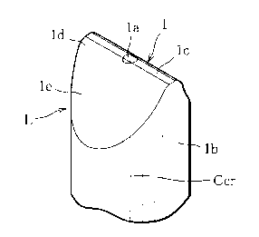
The wedge-shaped end optical fiber 1 is, as shown a.n
FIG. 1 and FIG. 2, a silica glass optical fiber of a diameter
of 125 pm comprised of a core la of a diameter of 6 um and a
cladding 1b surrounding the outside of the core.
The wedge-shaped end optical fiber 1 is processed to
form a wedge shaped lens portion L at its front end.
The lens portion L is comprised of a substantially flat
portion 1c, slanting faces 1e, and convex curved faces ld
formed between the substantially flat portion lc and slanting
faces le.
The substantially flat portion lc is formed to include
the end face of the core la and is formed to a width of at
least 1 pm (length in left-right direction in FIG. 2) in a
substantially planar shape perpendicular to the core center
axis Ccr.
More particularly, the substantially flat portion lc, as
shown in FIG. 2, is comprised of a center portion formed into
a mirror face FM by cleavage by a fiber cutter and of
remaining portions formed by polished faces with large radii
of curvature. Due to this, the overall substantially flat
portion lc is formed into a planar shape with a large radius
of curvature.
Further, the slanting faces 1e are formed by polishing
the two sides of the substantially flat portion 1c
symmetrically with respect to the core center axis Ccr. The
slanting faces 1e are mainly faces from which the front end
of the cladding lb is exposed, but may be formed reaching
part of the core 1a as well.
The convex curved faces 1d are formed from the front end
of the core la by polishing between the substantially flat
portion lc and the slanting faces le. Compared with the
CA 02328549 2000-12-15
9
substantially flat portion 1c, they have extremely small
radii of curvature.
As one example, the wedge-shaped end optical fiber 1 is
formed with a width of the substantially flat portion 1c of
2.4 pm or 0.4 time the diameter of the core la and formed
with a width of the mirror face FM of 1.2 pm or half of the
width of the flat portion lc. The average radius of curvature
of the substantially flat portion 1c is extremely large due
to the mirror face FM. The convex curved faces 1d are formed
with radii of curvature of 5 pm. The angle 8 formed by the
two slanting faces le is 80°.
The wedge-shaped optical fiber 1 receives the strongest
portion of light in the distribution of intensity at the
substantially flat portion lc. The mirror face FM of the
substantially flat portion 1c is comprised of a cleaved face
of the optical fiber, so is not formed on the surface with
the affected layer characteristic of a polished face.
Further, the convex curved faces ld around the mirror face FM
can be finely polished using a cerium oxide or other
polishing tape etc. causing a mechanochemical reaction on the
silica at the time of polishing so as to remove almost all of
the affected layer.
The affected layer means a layer where a refractive
index has changed from a predetermined value due to damage
due to the polishing and becomes a cause of reduction of the
optical coupling efficiency due to surface reflection at the
lens portion L.
The wedge-shaped end optical fiber 1 of the present
embodiment is improved in the optical coupling efficiency by
making the center portion of the lens portion L receiving the
CA 02328549 2000-12-15
light, that is, the portion receiving the particularly strong
light, the mirror face FM free from the affected layer.
Further, the wedge-shaped end optical fiber 1 can be
given a high lens effect by the formation of the convex
5 curved faces 1d, light can be sufficiently pulled into the
core la, and the optical coupling efficiency can therefore be
improved.
Therefore, the wedge-shaped end optical fiber 1 can be
improved further in the optical coupling efficiency by
10 setting the width of the mirror face FM to be at least 0.5
time the width of the substantially flat portion lc.
Further, the wedge-shaped end optical fiber 1 can be
given a suitable flatness at the substantially flat portion
lc and can be given a suitable lens effect at the convex
curved faces ld as well by setting the average radius of
curvature of the substantially flat portion 1c to more than
at least 10 times the radii of curvature of the convex curved
faces 1d.
The wedge-shaped end optical fiber 1 having this
characteristic may be produced using optical fibers of all
different types of compositions such as a silica based
optical fiber mainly comprised of SiOz, a SiOz-NazO-Ca0 based,
SiOz-B203-Na20 based, alkali free Ga202-Ge02-Pz05 based, or
other multi-composition based optical fiber, or a fluoride-
based optical fiber.
A wedge-shaped end optical fiber 1 having such a shape
is produced using the production apparatus explained below.
The production apparatus 10, as shown in FIG. 4 and FIG.
5, is provided with a holding unit 20 serving as the holder
and a first processing unit 30 and second processing unit 35.
CA 02328549 2000-12-15
11
The holding unit 20 is mounted on a first support base
11, holds the optical fiber Fb, and moves in the direction of
three axes of an arrow Y parallel to the core center axis Ccr
(see FIG. 6) and arrows X and Z perpendicular to this (see
FIGS. 4 and 5). The holding unit 20 is provided with a fiber
chuck 21, a first slide table 22, a Y-axis adjuster 23, a
second slide table 26, an X-axis adjuster 27, and a Z-axis
adjuster 28. Here, the first support base 11 is supported at
its four corners by four legs 12. A monitor 18 is provided at
a position facing the holding unit 20.
The monitor 18 is a camera provided with the function of
a microscope which measures the polishing conditions such as
the width or shape of the portion of the wedge shape formed
on the front end of the optical fiber Fb by the first
processing unit 30 and second processing unit 35 and judges
the quality of the polishing.
The fiber chuck 21, as shown in FIG. 4 and FIG. 6, has
two holding plates 21a and 21b (see FIG. 6) and is formed
with a V-groove (not shown) for positioning and holding the
optical fiber Fb at the center of one of the facing surfaces.
The first slide table 22 is a table sliding in the Y-axis
direction and can detachably secure the fiber chuck 21 to it
by screws 22a. The first slide table 22 is driven in the Y-
axial direction illustrated in the figure by a Y-axis
adjuster 23. The Y-axis adjuster 23 is a means provided with
a micrometer for adjusting the position of the first slide
table 22 in the Y-axial direction. It can finely adjust the
position in units of 0.1 pm at the smallest. The X-axis
adjuster 27 and the Z-axis adjuster 28 also have the same
precisions of positional adjustment as the Y-axis adjuster
23. Further, the Y-axis adjuster 23 is used for moving the
CA 02328549 2000-12-15
12
first slide table 22 in the Y-axial direction for focusing
when observing the front end of the optical fiber Fb by the
monitor 18.
The second slide table 26 is a slide member able to
slide in the X-axial direction and is driven by the X-axis
adjuster 27 to move in the X-axial direction. The third slide
table 29 is driven by the Z-axis adjuster 28 to move in the
Z-axial direction together with the second slide table 26.
The first and second processing units 30 and 35 are
units for processing the front end of the optical fiber Fb
held by the holding unit 20 into a wedge shape and are
provided on a second support base 13. The second support base
13, as shown in FIG. 5, is supported by four support columns
14 and 15 provided at the first support base 11.
The first processing unit 30, as shown in FIG. 4, is
provided with a polishing tape Tab, a takeup reel 31, a
transport roller 32, a pressing member 33, and a back member
34.
Here, the second processing unit 35 is provided with a
polishing tape Tab, a takeup reel 36, a transport roller 37,
a pressing member 38, and a back member 39 and has the same
structure and action as the first processing unit 30.
Therefore, the first processing unit 30 will be explained,
while corresponding reference numerals will be used for
corresponding portions of the second processing unit 35 in
the following explanation and FIG. 4 to FIG. 6 and
overlapping explanations omitted.
The takeup reel 31 is provided with a reel 31a for
taking up the polishing tape Tab fed out from a feed reel 13a
and a motor 31b for turning the reel 31a. The motor 31b is
CA 02328549 2000-12-15
13
provided on the second support base 13. The feed reel 13a is
rotatably supported on the second support base 13.
Here, the first processing unit 30 feeds out the
polishing tape Tab from the feed reel 13c, passes it through
the guide roller 13b, the back member 34, the guide roller
13c, the transport roller 32, and the pressing member 33, and
takes it up at the takeup reel 31. On the other hand, the
second processing unit 35 feeds out the polishing table Tab
from the feed reel 13d, then passes it through the guide
roller 13e, back member 39, guide roller 13c, transport
roller 37, and pressing member 38, and takes it up at the
takeup reel 36.
The transport roller 32 is provided with a roller 32a
and a drive motor 32b provided at the second support base 13
for driving the rotation of the roller 32a.
The pressing member 33 is provided with a swing arm 33a,
a pressing roller 33b provided at the end of the swing arm
33a, and a spring 33c. The pressing roller 33b is pressed
against the roller 32a by a predetermined pressing force by
the spring 33c engaged at one end to the second support base
13 and the other end at the swing arm 33a. Due to this, the
polishing tape Tab is transported by a predetermined speed by
the transport roller 32 and the pressing member 33.
The back member 34 is made of stainless steel or another
material, abuts against the polishing tape Tab from the back,
and therefore polishes the optical fiber Fb held by the
holding unit 20 to a wedge shape. The back member 34, as
shown in FIG. 6, is formed at the front end facing the
optical fiber Fb with an abutting face 34a which is tapered
and abuts against the back of the polishing tape Tab. The
CA 02328549 2000-12-15
14
back member 34, as shown in FIG. 4 and FIG. 5, is attached to
a support block 13g of the second support base 13.
The production apparatus 10 is comprised as explained
above. The wedge-shaped end optical fiber 1 is produced by
the process of production explained below.
(Step A)
First, the front end of a silica glass optical fiber of
a diameter of 125 pm comprised of a core of a diameter of 6
pm and a cladding surrounding the outside of the same is
cleaved by a fiber cutter to form a planar portion PPL (see
FIG. 3C) substantially perpendicular to the core center axis
Ccr.
That is, as shown in FIG. 3A, first, the optical fiber
Fb is fixed at predetermined intervals in the longitudinal
direction by a fiber holders 51 and 52 and given a notch 54
at the side face of the optical fiber Fb by a circular blade
53. Next, as shown in FIG. 3B, the optical fiber Fb is pushed
up by a fixture 55 from the side opposite to the notch 54 to
cause a tensile stress at the optical fiber Fb and cleave it.
When cleaved in this way, the optical fiber Fb, as shown in
FIG. 3C, is formed at the end with a planar portion PPL
substantially perpendicular to the core center axis Ccr and
comprising a mirror face.
(Step B)
Next, the optical fiber Fb is positioned in the V-groove
with the planar portion PPL projecting out and held by the
two holding plates 21a and 21b. In that state, the fiber
chuck 21 is screwed to the first slide table 22.
Next, the X-axis adjuster 23, Y-axis adjuster 27, and Z
axis adjuster 28 of the holding unit 20 are used, as shown in
FIG. 4, to finely adjust the optical fiber Fb to face the
CA 02328549 2000-12-15
monitor 18 and be positioned corresponding to the abutting
faces 34a and 39a of the left and right back members 34 and
39. This position is the initial position of the holding
unit 20 at the time of start of polishing.
5 Next, the motor 31b and the drive motor 32b are
activated to feed out the polishing tape Tab from the feed
reel 13a and transport it, as shown in FIG. 4, through the
guide roller 13b, back member 34, guide roller 13c, transport
roller 32, and pressing member 33 to the takeup reel 31 at a
10 predetermined speed to start the polishing of the optical
fiber Fb. The polishing tape Tab used at this time is a tape
of a width of 60 mm comprised of a substrate of polyester
etc. on which is adhered alumina powder of an average grain
size of 3 pm.
15 When polishing the end of the optical fiber Fb to a
wedge shape, first, the X-axis adjuster 27 is used to make
the second slide table 26 move along the X-axis to the left
direction of FIG. 4. The position is monitored by the monitor
18, then the front end of the optical fiber Fb is made to
abut against the polishing tape Tab at the back member 34
side. One side of the optical fiber Fb is polished as shown
in FIG. 7A by the polishing tape Tab transported at the
predetermined speed to form a slanting face Fs.
Next, the X-axis adjuster 27 is used to make the second
slide table 26 move along the X-axis in the right direction
of FIG. 4. The position is monitored by the monitor 18, then
the front end of the optical fiber Fb is made to abut against
the polishing tape Tab at the back member 39 side. The other
side of the optical fiber Fb is polished as shown in FIG. 7B
by the polishing tape Tab transported at the predetermined
speed to form another slanting face Fs. Due to this, as shown
CA 02328549 2000-12-15
16
in FIG. 8, the end of optical fiber Fb is processed into a
wedge shape having a portion of a width of 10 pm
perpendicular to the core center axis Ccr as the mirror face
FM and two slanting faces Fs. At this time, angular ridges R
are formed between the mirror face FM and the slanting faces
Fs of the optical fiber Fb.
At step B, a back member 34 having an angle 81 of 40
degrees formed between the core center axis Ccr and the taper
34a shown in FIG. 6 is used so that the angle 8 formed
between the two slanting faces 1e in the wedge-shaped end
optical fiber 1 produced (see FIG. 2) becomes 80 degrees.
(Step C)
Next, as shown in FIG. 6 and FIG. 9, the back members 34
and 39 are changed to back members 41 and 42 formed with
grooves 41b and 42b at the abutting surfaces 41a and 42a and
having angles 82 of 45 degrees formed between the abutting
surfaces 41a and 42a and the core center axis Ccr. Further,
the polishing tape Tab is changed to one of a finer average
grain size (here, less than 1 um). Next, the holding unit 20
is used to polish the front end of the optical fiber Fb, that
is, the portion of the ridges R between the mirror face FM
and the slanting faces Fs, by an operation similar to the
above.
At this time, as shown in FIG. 9, the back member 41 is
formed with a groove 41b at its abutting surface 41a.
Therefore, by making the portion of the ridge R of the wedge-
shaped end optical fiber Fb abut against the surface of the
polishing tape Tab corresponding to the groove 41b, the
polishing tape Tab becomes depressed as illustrated at the
portion of the groove 41b. As a result, the optical fiber Fb
CA 02328549 2000-12-15
17
is shaped by the depressed polishing tape Tab so that the
portion of the ridge R forms a convex curved face.
Therefore, by the production apparatus 10 and process of
production of the present invention, a wedge-shaped end
optical fiber 1 shown in FIG. 1 having a substantially flat
portion lc perpendicular to the core center axis Ccr and
including a partial mirror face and having slanting faces le
adjoining the substantially flat portion 1c through convex
curved faces ld and therefore a front end shaped as a wedge
is formed.
Here, a silica glass fiber of a diameter of 125 pm
having a core of a diameter of 6 um and a cladding
surrounding the outside of the same was used to produce
wedge-shaped end optical fibers 1 with widths of the
substantially flat portions 1c of various widths larger than
0.5 um and smaller than 3.5 pm by the process of the present
invention using the production apparatus 10. These were
coupled with 980 nm wavelength laser diodes and the coupling
efficiency measured. The results are shown in FIG. 10.
As clear from the results shown in FIG. 10, the wedge-
shaped end optical fiber 1 gives a high coupling efficiency
of over 80 percent if the width of the substantially flat
portion lc is 0.2 to 0.6 time the core diameter. If outside
this range, it was learned that the coupling efficiency
rapidly fell. Therefore, the wedge-shaped end optical fiber 1
preferably has a width of the substantially flat portion lc
of 0.2 to 0.6 time the core diameter.
Further, while the coupling efficiency was about 80
percent in the conventional lensed optical fiber disclosed in
U.S. Patent No. 3,910,677, the coupling efficiency is
CA 02328549 2000-12-15
18
increased to 89 percent in a wedge-shaped end optical fiber 1
with a width of the substantially flat portion 1c of 2.2 pm.
Here, if use is made of a fiber chuck 21 having two
holding plates extending long in the Z-axial direction and
formed at predetermined intervals in the Z-axial direction
with a plurality of V-grooves for positioning and holding
optical fibers Fb at the center of one of the facing
surfaces, it is possible to produce a plurality of wedge-
shaped end optical fibers 1.
In this case, at step B, a polishing tape Tab of a wide
width of about 60 pm is used to polish a plurality of optical
fibers Fb all together, while at step C, the optical fibers
Fb are made to move in the Z-axial direction to successively
finely polish the optical fibers Fb one at a time. At step C,
the polishing tape Tab is preferably made one of a narrower
width than step B (for example, a width of about 6 mm) so as
not to interfere with the adjoining optical fiber Fb when
polishing a predetermined optical fiber Fb.
The wedge-shaped end optical fibers 1 produced in this
way are suitable for receiving light having a mode field of
an elliptical sectional shape.
Further, if the production apparatus 10 is configured to
enable the holding unit 20 provided with the fiber chuck 21
for holding an optical fiber Fb to rotate about the Y-axis,
it is possible to produce a lensed optical fiber 2 as shown
in FIG. 11 having a core 2a and a cladding 2b surrounding the
outside of the core, having part of the substantially flat
portion 2c perpendicular to the core center axis Ccr formed
by a mirror face, having slanting faces 2e formed through
convex curved faces 2d adjoining the substantially flat
CA 02328549 2000-12-15
19
portion 2c, and therefore shaped as a cone with the top cut
away.
Such a lensed optical fiber 2 is suitable for receiving
light having a mode field of a circular sectional shape.
In this way, the lensed optical fiber of the present
invention can be formed into suitable lens shape for the
shape of the mode field of the light emitted from the laser
diode.
Next, a lensed optical fiber and process of production
of the same according to a second embodiment of the present
invention will be explained with reference to FIG. 12 to
FIGS. 16A and 16B.
First, the wedge-shaped end optical fiber of this
embodiment will be explained based on FIG. 12.
The wedge-shaped end optical fiber 5, as shown in FIG.
12, is a silica glass optical fiber having a core 5a and a
cladding 5b surrounding the outside of the core and has a
front end formed into a wedge shape by slanting faces 5e
formed via convex curved faces 5d at the two sides of a
substantially flat portion 5c. At this time, in the wedge-
shaped end optical fiber 5, parts of the outer circumference
of the core 5a are polished, a flat portion 5c is formed in
the diametrical direction having a width of at least 1 pm at
the core center axis Ccr, and this is connected to the
slanting faces 5e through the convex curved faces 5d.
The wedge-shaped end optical fiber 5 is different from
the wedge-shaped end optical fiber 1 in that all of the
substantially flat portion 5c is formed by a polished face.
The wedge-shaped end optical fiber 5 having this shape
is produced by for example the process explained below.
CA 02328549 2000-12-15
First, as shown in FIG. 13A and FIG. 13B, a plurality of
optical fibers Fb are inserted into a plurality of optical
fiber holes (not shown) of a holder 7 so that the front ends
project out slightly from the end face 5a. These are then
5 temporarily secured by a wax adhesive Awx.
As the plurality of optical fibers Fb, use is made of a
plurality of optical fibers made of silica glass fibers
formed into a tape, that is, a tape fiber Ftp, from which the
jackets on the front end portions have been removed to
10 separate the individual optical fibers Fb. Further, as the
holder 7, use is made of a multi-fiber connector ferrule with
a plurality of optical fiber holes formed in a single row at
a high precision.
(Step A)
15 Next, the holder 7 is subjected to the first processing.
In this processing step, the plurality of optical fibers Fb
and the holder 7 are ground flat by for example a diamond
grindstone of a 10 um average grain size so that the end face
perpendicular to the axes of the optical fibers Fb becomes
20 flat. The wax adhesive Awx at the end face is also removed.
(Step B)
Next, in the same way, the holder 7 is ground so that
the shape of the front end in the width direction
perpendicular to the direction of arrangement of the optical
fibers Fb becomes, as shown in FIG. 14A and FIG. 14B, a
trapezoidal shape having a planar face Fe perpendicular to
the optical axes of the optical fibers Fb (that is, the core
center axes Ccr) and containing all of the end faces of the
cores CR of the optical fibers Fb and slanting faces Fs
formed at the two sides of the planar face Fe and symmetrical
with respect to the planar face Fe.
CA 02328549 2000-12-15
21
At this time, when the optical fibers Fb are for example
single mode fibers of core diameters of about 6 pm, the two
slanting faces Fs of the holder are polished symmetrically
with respect to the optical axes of the optical fibers Fb so
that the width W1 of the planar face Fe becomes about 80 pm
and the angle a formed by the two slanting faces Fs becomes
about 55 degrees. The holder 7 can prevent polishing loss
reaching the cores CR of the optical fibers by leaving a
width W1 of the planar face Fe of about 80 pm.
Next, using a grindstone fabricated from an abrasive
containing cerium oxide (average grain size of 1 pm), the
planar face Fe of the holder 7 is finely polished and the two
side faces Fs are finely polished to a predetermined width W2
(pm) shown in FIG. 15B. At this time, the slanting faces Fs
of the holder 7 are finely polished so that the planar face
Fe has a width in the range of 1/3 to 3 times the core
diameter between the outside of the cores CR and the ridges R
formed by the planar face Fe and the slanting faces Fs. That
is, the two slanting faces Fs of the holder 7 are finely
polished symmetrically with respect to the optical axes of
the optical fibers Fb so that, as shown in FIG. 15A and FIG.
15B, when the diameter of a core CR is Dcr and the widths
between the outside of the cores CR and the ridges R formed
by the planar face Fe and the slanting faces Fs are bl and 82
(pm), the width W2 of the planar face Fe becomes as expressed
in the following equation and so that the angle B formed by
the two slanting faces Fs becomes about 60 degrees:
W2 = b1+b2+Dcr
For example, when the optical fibers Fb have core
diameters of 6 pm, the widths 81 and b2 between the outsides
of the cores CR and the ridges R formed by the planar face Fe
CA 02328549 2000-12-15
22
and the slanting faces Fs are preferably equal. It is best
that the slanting faces Fs be polished symmetrically with
respect to the optical axes of the optical fibers Fb.
Further, the widths b1 and b2 are set in the following range:
2 < bl , b2 < 15
At this time, if the widths 81 and b2 become less than 2
pm, it will not be possible to obtain smooth convex curved
faces in the later explained second processing step, while if
over 15 um, the radii of curvature of the obtained convex
curved faces will become too great and the lens effect in a
specific direction aimed at by the wedge-shaped end optical
fibers 5 produced will not be able to be exhibited.
Therefore, when set in this way, the width W2 (~,m) of
the planar face Fe becomes one of the range expressed by the
following relationship:
10 < W2 < 36
By processing in this way, the holder 7, as shown in
FIG. 15A and FIG. 15B, is polished to a trapezoidal shape
comprised of the planar face Fe having optical fibers Fb
temporarily secured partially polished at the cladding CL,
having widths between the outsides of the cores CR and the
ridges R of 81 and 82, and having an overall width of W2 and
two slanting faces Fs, thereby completing the first
processing step. ,
In this fine polishing, a grindstone fabricated from an
abrasive containing cerium oxide is used as explained above.
Therefore, the holder 7 is polished along with the optical
fibers Fb to superior flatnesses of the planar face Fe and
the two slanting faces Fs by the mechanochemical action and
to mirror faces free from the above affected layers.
(Step C)
CA 02328549 2000-12-15
23
Next, the holder 7 is subjected to second processing. In
this processing step, the portions of the ridges R formed by
the planar face Fe and slanting faces Fs of the holder 7 are
mainly buffed using an abrasive containing said cerium oxide.
At the time of this buffing, the adjacent portions along the
ridges R of the planar face Fe and the slanting faces Fs of
the holder 7 are also polished. Therefore, the holder 7 is
formed at the front end along the centers of the cores CR of
the plurality of optical fibers Fb, as shown in FIG. 16A and
FIG. 16B, with a substantially flat portion FL having a width
of at least 1 pm and convex curved faces FCB connected to the
slanting faces Fs at the two sides of the flat portion FL. At
the flat portion FL, the optical fibers Fb are polished
slightly at the outsides in the width direction of the cores
CR (see FIG. 16B).
At this time, in the second processing step, the holder
7 is polished so as to give radii of curvature of the convex
curved faces FCB of 3 to 6 u, more preferably 3.5 to 5.5 pm,
in accordance with the characteristics of the laser diode
optically coupled with the wedge-shaped end optical fibers 5
produced. Here, the holder 7 is formed with the substantially
flat portion FL at its front end by the second processing,
but this does not necessarily have to be a planar face. That
is, the flat portion FL may be deemed to be a substantially
flat portion FL if having a radius of curvature of at least
10 times the radii of curvature of the convex curved faces
FCB formed at the two sides. Further, at the time of
completion of the processing, the convex curved faces FCB of
the holder 7 are, as shown in FIG. 16A, polished
symmetrically with respect to the optical axes of the optical
CA 02328549 2000-12-15
24
fibers Fb so that the angle y formed by the two slanting
faces Fs becomes about 70 degrees.
After the second processing step is finished in this
way, the holder 7 is heated to melt the wax adhesive Awx, the
plurality of optical fibers Fb are taken out from the
plurality of optical fiber holes (not shown), and the
deposited wax adhesive Awx is cleaned off, whereby a
plurality of wedge-shaped end optical fibers 5 are obtained
all at once.
In this way, according to the process of production of
the present embodiment, by using the holder 7, it is possible
to process a plurality of optical fibers all at once.
Further, this process of production finely polishes the ends
to planar faces by a grindstone fabricated from an abrasive
including cerium oxide in the first processing step and buffs
mainly the portions of the ridges R formed by the flat face
Fe of the holder 7 and the slanting faces Fs using an
abrasive containing cerium oxide in the second processing
step. Therefore, the wedge-shaped end optical fiber 5
produced does not have a depressed end face of the core and
has a flat portion processed to a mirror face, so has a
sufficient optical transmission performance and has an amount
of attenuation of reflection, when measured, of at least 55
dB.
Further, when the wedge-shaped end optical fiber of the
present invention and the wedge-shaped end optical fiber
produced by the process of the prior art were optically
coupled with 980 nm wavelength band laser diodes, it was
found that the coupling distance could be increased 1.2 to
1.5 times from the prior art and the coupling efficiency
could be improved.
CA 02328549 2000-12-15
Next, an example of a laser diode module of the present
invention using a lensed optical fiber of the first and
second embodiments will be explained based on FIG. 17.
As shown in FIG. 17, the laser diode module 100 is
5 comprised of a package 101 with a bottom plate 101a on which
are successively arranged a Peltier module 102 for
dissipating heat, a base 103, a chip carrier 104, and a laser
diode 105. The lensed optical fiber 107 is arranged so that
the lens portion L faces the light emitting end face of the
10 laser diode 105 and is affixed on the base 103 through a
fiber fixing member 106. The lensed optical fiber 107 is led
outside of the package 101 through a sleeve 109 provided in a
tubular hole 108.
In this laser diode module 100, when light is emitted
15 from the light emitting end face of the laser diode 105 and
inputting the light into the tensed optical fiber 107 through
the lens portion L, the tensed optical fiber 107 has an
extremely high coupling efficiency of light at the lens
portion L as explained by the wedge-shaped end optical fibers
20 1, 2, and 5 of the first and second embodiments. The laser
diode 105, further, has light strongest at the portion of the
optical axis as clear from FIG. 18 showing the distribution
of relative intensities of light emitted in a direction
perpendicular to the optical axis. Therefore, the laser diode
25 module 100 is improved in output from the prior art. In
particular, a rare earth element doped fiber type optical
amplifier or Raman optical amplifier etc. requires a laser
diode module serving as a high output excitation source, so
the laser diode module 100 with the high optical coupling
efficiency is suitable for use for this.