Note : Les descriptions sont présentées dans la langue officielle dans laquelle elles ont été soumises.
CA 02328691 2001-03-12
PRINTER
s This invention relates to a printer having a structure for
printing a recording paper fed from a recording rolled paper such
as a rolled label sheet with base sheet and for separating a label
from a base sheet after printing. Specifically, the invention
relates to a printer in which a recording rolled paper loading
to operation becomes easy.
In General, at a shopping center, a distribution center
or the like, a label which indicates the final destination or the
like is attached to cargo to be delivered. Normally, the printing
is operation is applied to the labels adhered on a base sheet. Then,
the labels are separated one by one from the base sheet and are
attached to the cargo.
Conventional printers for this purpose are disclosed in
Unexamined Japanese Patent Publication Hei. 8-295323, Japanese
zo Patent 2633726 or the like. These publications show a separating
structure wherein the labels are automatically separated from the
base sheet after printing.
As shown in these publications, a label printer includes
a roll-accommodating portion in a body. The recording rolled paper
zs is accommodated in this portion, and the label sheet is fed from
1
CA 02328691 2001-03-12
this portion. After passing through a printing portion, the
printed labels are separated from the base sheet by transporting
the label sheet through a transporting path with a curled portion.
Then, the label is discharged from a discharging port formed on
s a cover of the roll accommodating portion.
In the above-described construction, it is preferable to
be able to easily operate the cover when the recording rolled paper
is loaded. Further, when new roll paper is loaded, it is preferable
to easily satisfy the condition by a simple operation, that is,
to the label sheet fed from a recording rolled paper travels along
the transporting path with the curled portion, as a constituent
of the separating structure, and is pulled off to an external portion
of the printer body.
is In this kind of the label printer, however, a space for
opening the cover is required in vicinity of the printer. When the
cover is designed as a swing cover-wherein two swing covers pivot
in opposite directions when moving from a closed position in which
they are relatively close to each other the necessary space for
zo two doors is smaller than that for a single cover. This is
desirable.
But if two swing covers are used, it is necessary to operate
each swing cover. Further, if the covers must be opened in turn,
an operation error tends to occur.
2
CA 02328691 2001-03-12
An object of the present invention is to provide a printer
in which an printer body has a recording rolled paper accommodating
portion that includes an opening portion constituted by swing
s covers pivoting in opposite directions when moving away from the
positions in which they are relatively close to each other
characterized in that as the swing covers are being closed, the
label sheet fed from a recording rolled paper travels along a
transporting path so as to have a curled portion-as a constituent
to of the separating structure-and is pulled off to an external
portion of the printer body.
Another object of the present invention is to provide a
printer having a pair of swing covers characterized in that an
open/close operation becomes easy.
is In view of the above objects, according to a first aspect
of the preset invention, there is provided a printer comprising:
a printer body having an accommodating portion for
accommodating a rolled paper;
a opening for loading the rolled paper into the
zo accommodating portion;
first and second swing covers, for opening and closing the
opening, said first and second swing covers being mounted to the
printer body so as to move away from a closed position in which
they are close to each other;
Zs a printing head which prints on the paper fed from the
3
CA 02328691 2001-03-12
rolled paper accommodated in the accommodating portion;
a platen member mounted on the first swing cover and
confronted with the printing head portion when the first swing cover
is closed;
s a first guide member provided with the first swing cover,
and positioned downstream, in a paper transporting direction, with
respect to the printing head and the platen member when the first
swing cover is closed; and
a second guide member, provided with the second swing cover,
to said second guide member positioned in vicinity of said first guide
member when the first and second swing cover are closed,
wherein said first and second guide members guide the paper
so as to incurvate the paper on the first guide member .
According to the present invention, a separator defined
is by the first guide member transports the label sheet along the curved
transporting path, and such is automatically accomplished by
closing the first and second swing covers.
When the first and second swing covers are closed, the first
guide member is positioned on the same side of the thermal printing
zo head as is the platen member. Also, the second guide member is
positioned at the same side of the first guide member. If the second
guide member is set far from the first guide member, the separator
for transporting the recording medium along with the curved
transporting path becomes simple.
zs Further, the second guide member is defined by a
4
CA 02328691 2001-03-12
sheet-pressing roller adjustably mounted,on thesecondswing cover,
in the sheet pressing direction. An elastic member urges the
sheet-pressing roller in the sheet pressing direction.
In the above-described construction, the label sheet is
s wound by the first guide member-urged by the elastic force of the
elastic member-with a predetermined tension. Thus, the label
surely is separated from the base sheet.
Next, the printer of the present invention may employ a
lock mechanism for locking the first and second swing covers in
to a closed condition.
The lock mechanism contains a lock lever mounted on one
of the first and second swing covers, a cover-side lever-engagement
portion provided with the other swing cover, and a main-body-side
lever-engagement portion. When the first and second swing covers
is are closed, a cover-side engagement portion located on the lock
lever is engaged with the cover-side lever-engagement portion, and
a main-body-side engagement portion is engaged with the main-
body-side lever-engagement portion.
In this construction, when the swing cover which does not
zo have the lock lever is firstly closed, the swing cover is not locked.
Thus, the operator must perform a closing operation such that the
pair of swing covers is closed in the predetermined turn, whereby
the second guide member surely separates the label from the base
sheet.
25 Further, a single lock lever locks both swing covers,
CA 02328691 2001-03-12
thereby simplifying the open/close operation.
The cover-side engagement portion and the main-body-side
engagement portion rotate between a lock position (wherein the
cover-side engagement portion and the main-body-side engagement
s portion engage with the cover-side lever-engagement portion and
the main-body-side lever-engagement portion, respectively) and an
unlock position(wherein these engagements are released). Further,
the lock mechanism further contains an elastic member for urging
the lock lever to the lock position, a manual operating member for
to rotating the lock lever toward the unlock position against an urging
force of the elastic member, and an urging member for urging the
swing cover-which is not provided with the lock lever-in a
swing-cover opening direction.
Instead of the construction described above, the lock
is mechanism may contain a lock lever mounted on the second swing cover,
a first-swing-cover pressing portion provided with thesecondswing
cover, a main-body-side lever-engagement portion provided with a
printer main body, and a main-body-side engagement portion engaged
with the main-body-side lever-engagement portion when the lock
lever closes the second swing cover, wherein a first swing cover
pressing portion provided with the second swing cover presses the
first swing cover to a closing direction thereof when the second
swing cover is closed.
In this construction, one swing cover maintains the other
zs swing cover in the closed condition. Thus, when the one swing cover,
6
CA 02328691 2001-03-12
which does not have the lock lever, is firstly closed, it is not
ffixed in the closed condition.
In this case, the first-swing-cover pressing portion
corresponds to the second guide member, and it is preferable that
s the second guide member is capable of pressing the platen member
provided with the first swing cover toward the closing direction
when the second swing cover is closed.
Further, it is preferable that the lock mechanism further
contains an urging member for urging the second swing cover in the
to opening direction. In this construction, when the first swing
cover is opened, the second swing cover which was held in the closed
condition is automatically opened.
Moreover, the printer of the present invention contains
a cuter blade for cutting the recording medium after printing. The
is cutter blade is positioned downstream-in the recording medium
feeding direction-9f the printing head and the platen member.
In this situation, an opening for discharging the recording
medium is provided by the first and second swing covers, at a
position adjacent the printing head portion and the platen member,
zo when the first and second swing covers are closed. And the cutter
blade is positioned adjacent to the opening for discharging the
recording medium. With this construction, upon closing the first
and second swing covers, the cutter blade could cut the label sheet
or the like. It is possible to provide the cutter blade with the
~s first guide member.
CA 02328691 2001-03-12
Next, according to the present invention, the printing head
includes a thermal head, and the platen member includes a platen
roller. In this case, when the first cover is closed, the platen
roller is brought into contact with the thermal head.
s
The above and other objects and advantages of the present
invention will become more apparent by describing in detail
preferred exemplary embodiments thereof with reference to the
to accompanying drawings, wherein like reference numerals designate
like or corresponding parts throughout the several views, and
wherein:
Fig. 1 is a side view showing a schematic configuration
of a printer according to an embodiment of the invention;
is Fig. 2 is a side view showing both swing covers closed;
Figs . 3 ( a ) and ( b ) are a plan view and a partial side view,
respectively, of a first cover frame of a first swing cover of the
printer in Fig. 1;
Figs . 4 ( a ) and ( b ) are a plan view and a partial s ide view,
zo respectively, of a second cover frame of a second swing cover of
the printer in Fig. l;
Fig. 5 is a side view showing both swing covers, of the
printer in Fig. 1, open;
Fig. 6 is a side view showing a condition wherein the first
2s swing cover, of the printer in Fig. 1, is closed;
8
CA 02328691 2001-03-12
Fig. 7 is a side view showing the second swing cover, of
the printer in Fig. 1, partially closed;
Fig. 8 is a side view showing the second swing cover in
contact with a lock lever of the printer in Fig. 1;
s Fig. 9 is a side view showing the second swing cover almost
completely closed, i.e., just before the condition shown in Fig.
1;
Figs . 10 ( a ) and ( b ) are partial cross sectional views of
another embodiment of the present invention;
to Fig. 11 is a partial cross sectional view of modified
embodiment of Fig. 10;
Fig. 12 is a partial cross sectional view of a second
modified embodiment of Fig. 10; and
Fig 13 is a partial cross sectional view of a third
is embodiment of the present invention.
Referring to the drawings, preferred embodiments of a
printer according to the present invention will be described in
zo detail below.
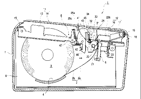
Fig. 1 is a perspective sectional view of a main part of
a label printer of the present invention. Fig. 2 is an enlarged
partial sectional view of Fig. 1.
According to this embodiment of the present invention, a
~s label printer 1 includes an accommodating portion 4 which holds
9
CA 02328691 2001-03-12
a recording rolled paper 3 having a label sheet 2 wherein labels
2b are adhered on a tape like base sheet 2a having a constant width.
A thermal head 5 prints the label 2b of the label sheet as the
label sheet is fed from the recording rolled paper. Further, the
s label 2b is separated from the base sheet 2a, after printing, to
discharge it out of the printer body. Of course, the label printer
1 is capable of printing on a normal ( non-label ) recording paper.
As shown in Figs. 1 and 2. the label printer 1 has a
rectangular shaped main case 7. The main case 7 contains a main
to frame 8, made of metal or the like, having a pair of side plates
parallel to each other with a predetermined distance defined
therebetween. The side plates are mounted so that the
predetermined distance extends along a width direction of the
printer. The accommodating portion 4 is designed to feed the
is recording rolled paper 3 from an opening 6 in the main case 7, and
is arranged between the pair of side plates of the main frame 8.
Further, a thermal head 5 is mounted on a front portion of main
frame 8.
The opening 6 is closed by a first swing cover 11 and a
zo second swing cover 12 which pivot in opposite directions when moving
away from a closed position wherein they are relatively close to
each other. The first swing cover 11 includes a first cover frame
13 and a first cover case 14 attached to the first cover frame 13.
The first cover frame 13 is rectangularly shaped, and a
zs proximal end thereof is rotatably supported by a first axis 15
CA 02328691 2001-03-12
bridged to the main frame 8 in the width direction. Similarly, a
second swing cover 12 has a second cover frame 16 and a second cover
case 17.
Figs . 3 ( a ) and ( b ) respectively show plan and partial side
s views of the first cover frame 13, whereas Figs. 4 (a) and (b)
respectively show plan and partial side views of the second cover
frame 16. The structure of the first and second swing covers 11
and 12 will now be described with reference to the drawings.
The first cover frame 11 is rectangular in shape, and the
to proximal end thereof is rotatably supported by the first axis 15.
The second cover frame 16 is also rectangular in shape,
and a proximal end thereof is rotatably supported by a second axis
18 bridged to the main frame 8 in the width direction. Further,
the second swing cover 12 is urged toward an open direction by a
is twisted coil spring 19 mounted on the second axis 18.
The first cover case 14 and the second cover case 17 form
a case cover which closes the opening 6 in the main case 7.
A platen roller 21 is arranged along the printer width at
a tip end of the first cover frame 13 so that both ends of the roller
zo 21 are rotatably supported. When the first swing cover 11 is closed,
the platen roller 21 presses against the thermal head 5. The
thermal head is pivoted into pressing engagement with the platen
roller 21 by a compressed coil spring 23. The tip ends of the first
cover case 14 and the second cover case 17 are confronted with each
zs other when they are closed, and each has a rectangular notch so
11
CA 02328691 2001-03-12
that together they form an opening 24 for discharging a label sheet.
A first sheet-discharging guide portion 25a is formed on the first
cover case 14, at one end of the opening 24, so that it extends
along the printer width direction. A second sheet-discharging
s guide portion 25b is formed at the other end of the opening 24 and
extends in the printer width direction. Further, the printer body
contains third and fourth sheet discharging guide portions 25c and
25d for guiding the base sheet 2a toward the first sheet-discharging
guide portion 25a. As shown in Figs. 3(a) and (b), the third and
to the fourth sheet-discharging guide portions 25c and 25d are bridged
in the printer width direction at the tip end of the first cover
frame 13 .
Labe1_ sP~a_rati nc~ mechanism
Figs . 5 to 9 are perspective views showing a sequence of
is steps from the open condition of the first and second swing covers
to the close condition thereof. With reference to these drawings,
next will be described the structure by which a label, after printing,
is separated from the base sheet 2a of the label sheet 2.
According to the label separating mechanism of this
2o embodiment, there is provided a first guide member 31 serving as
sheet-curving roller extending in the printer width direction at
a tip end of the first cover frame 13, and a second guide member
32 serving as a sheet-pressing roller extending in the printer width
direction at a tip end of the second cover frame 16.
25 The first guide member 31 is rotatably supported and
12
CA 02328691 2001-03-12
adjunctively positioned above the platen roller 21. Namely, upon
closing the first swing cover 11, the first guide member 31 is
positioned at a side to which the label-after having passed between
the thermal head 5 and the platen roller 21-is fed. On the other
s hand, the second guide member 32 is positioned on the second cover
frame 16 such that the second guide member 32 is positioned at the
same side of the thermal head 5 as is the first guide member 31,
but is spaced farther from the thermal head than is the first guide
member 31. Further, the second guide member 32 is positioned at
to the same height as is the first guide member 31. Moreover, the
second guide member 32 is designed to slidably move along an elongate
hole 33 formed on the second cover frame 16 in an approximately
vertical direction.
A label separating operation, as performed by the
is above-described structure, will be described hereinbelow.
The label sheet 2 is fed from the accommodating portion
4 so that it passes, in an upward direction as shown in the Figures,
between the thermal head 5 and the platen roller 21. The label 2b
facing the thermal head 5 is printed with a predetermined character
zo or the like. After printing, only the base sheet 2a travels through
the first guide member 31 and under the second guide member 32.
Then, the base sheet 2a is discharged from the opening 24 , which
is formed by the tip ends of the first cover case 14 and the second
cover case 17 . The base sheet 2a is wound, by the second guide member
zs 32, to define an angle larger than a right angle with respect to
13
CA 02328691 2001-03-12
the first guide member 31. Thus, at this position, the label 2b
is transported in a label travel direction ( upper direction in the
Figure) due to the high label 2b stiffness so that it separates
from a surface of the base sheet 2a.
s In this embodiment, the second guide member 32 is urged
by a compressed coil spring 34 so as to apply a predetermined tension
to the base sheet 2a and, thereby, wind the base sheet 2a about
the first guide member 31. Thus, the label 2b surely is separated
from the base sheet 2a at this position.
to .wing cover lock mechan,'_sm
Next, with reference to Figures 1 to 9, the lock mechanism
will be explained. The lock mechanism locks the first and second
swing covers 11 and 12, as shown in Figs. 1 and 2, in a closed state.
The lock mechanism of the present invention contains a lock
is lever 41 mounted on a side of a tip end of the first cover frame
13. The lock lever 41 is rotatably supported on the first cover
frame 13 by a rotation axis which is located at an intermediate
position of the lock lever 41. The lock lever 41 contains a link
portion 41a and a lever body 41b. The link portion 41a extends in
zo the printer width direction. The lever body 41b is curved in a right
angle from both ends of the link portion 41a, and extends in a
longitudinal direction as shown in Figs. 3 (a) and (b). The lock
lever 41 also contains a cover-engagement surface 43 on an upper
portion thereof, and a main-body-engagement surface 44 on a lower
zs portion thereof. The cover-engagement surface 43 is engageable
14
CA 02328691 2001-03-12
with the second swing cover 12, and the main-body-engagement
surface 44 is engageable with the main frame 8.
Both side surfaces on the tip end of the second cover frame
17 contain a first lever-engagement projection 45, which is
s engageable with the cover-engagement surface 43 from a lower side.
Also, a second lever engagement projection 46 is engageable with
the cover-engagement surface 43 from an upper side, and is provided
on a surface of the side plate of the main frame 8.
Further, the lock lever 41 is always urged in a clockwise
to direction by a tension spring 47. However, the lock lever can not
rotate beyond a condition as shown in Fig. 5 due to the presence
of a stopper (not shown).
In this configuration, if only the first swing cover 11 is
closed from the open configuration as show in Fig. 5, the lock
is levers main body engagement surface 44 is brought into contact
with the second lever engagement projection 46. After that, the
lock lever 41 slightly rotates in a counterclockwise direction
against the spring tension, and runs over the second lever
engagement projection 46. As a result, as shown in Fig.6, the first
zo swing cover 11 is locked because the second lever engagement
projection 46 is engaged with the main body engagement surface 44
from the lower side.
Next, when the second swing cover 12 is closed, the first lever
engagement projection 45 is brought into contact with the upper
~s end portion of the lock lever 41 as shown in Fig. 8. As shown in
CA 02328691 2001-03-12
Fig. 9, when the second swing cover 12 is further pressed, the lock
lever4l slightly rotates in the counterclockwise direction against
the spring tension so as to allow the swing cover 12 to completely
close. At the completely closed condition, the first lever
s engagement projection 45 is positioned under the cover engagement
surface 43. As a result, the lock lever 41 rotates in the clockwise
direction-due to the spring tension-so that the second swing cover
12 is locked because the first lever engagement projection 45 is
engaged with the cover engagement surface 43 from the under side.
to To unlock the first 11 and second 12 swing covers, the lock
lever 41 rotates in the counterclockwise direction around an axis
42 in the direction of arrow A as shown in Fig. 3 (b) . For example,
there is a manual operation lever, mounted on an outside surface
of the printer body, which could rotate the lock lever 41. Then,
is this manual operation lever is rotated in the counterclockwise
direction to turn the lock lever 41 . When the lock lever 41 rotates
in the direction of arrow A against the spring force, it disengages
the lock lever 41 from the second lever engagement projection 46,
and brings the lock lever ~ s contact surface 41c into contact with
zo the support surface 41d provided with the printer main body frame
so as to lift up the first cover frame 13. As a result, even if
the manual operation lever is released to return the lock lever
to its initial position, the first swing cover 13 is not locked
again.
16
CA 02328691 2001-03-12
Becordina rolled pier loading
Next, this label printer 1, a rolled-paper loading operation
will described.
First, from the condition shown in Figs. 1 and 2, the lock
s lever 41 is slightly swung-by a manual operation lever (not
shown)-in the counterclockwise direction. As a result, the lock
lever 41 releases the locked condition so that the first and second
swing covers 11 and 12 can be opened. In this embodiment, the second
swing cover 12 is always urged, by a twist spring 19, in an open
to direction around an axis 18. Thus, as shown in Fig. 5, when the
lock is released, the second swing cover 12 is firstly placed in
a full open condition by a spring force.
Next, the first swing cover 11 is opened. Fig. 5 shows a half
open condition of the first swing cover 11. After fully opening
is the first swing cover 11, the recording rolled paper 3 is loaded
in the accommodating portion 4. After that, the label sheet 2 is
fed from the recording rolled paper 3, and is pulled out of the
opening 6 toward the upper direction. Under this condition, the
first swing cover 11 is closed.
2o When the first swing cover 11 partially is closed to certain
degree, the lower end portion of the lock lever 41 is brought into
contact with the second lever engagement projection 46. Next, as
described above, the lock lever 41 is slightly swung, by further
movement of the first swing cover 11, against the pulling force
zs of a coil spring 81 to run over the second lever engagement
m
CA 02328691 2001-03-12
projection 46. Then, the lock lever ~ s cover engagement surface 43
is engaged with the lower side of the second lever engagement
projection 46 from the lower side so that the first swing cover
11 is locked in a completely closed condition.
s As shown in Fig. 6, when the first swing cover is completely
closed, the label sheet 2 is interposed between the platen roller
21 and the thermal head 5. At this time, a fed portion of the
recording rolled paper 3 travels between the thermal head 5 and
the first guide member 31. Thus, the recording rolled paper 3 is
to rolled to a side of the first swing cover 11 due to a curl out so
as to face the tip end portion of the second swing cover 12 which
is open.
Next, when the second swing cover 12 is gradually closed, as
shown in Fig. 7, the part of the label sheet 2, which is fed to
is the upper side, is pressed downward by the second guide member 32.
The second swing cover 12 is further closed, as shown in Fig. 8,
so that the second guide member 32 approaches to the platen roller
21 and presses the label sheet 2 toward a side of the platen roller
21. As a result, the label paper 2 is wound with an angle more than
zo a right angle with respect to the first guide member 31 and is rolled
downwardly at this position.
As shown in Fig. 8, after the first lever engagement projection
45, of the second swing cover 12, contacts with the upper end portion
of the lock lever 41, the lock lever 41 is slightly swung-by further
zs closing of the second swing cover 12-in the counterclockwise
is
CA 02328691 2001-03-12
direction against the spring force. As a result, as shown in Fig.
9, the lock of the first swing cover 11 by the lock lever 41 is
temporally released. But after passing the second lever engagement
projection 46 over the upper portion of the lock lever 41, the lock
s lever is swung by spring force in the clockwise direction to again
lock the first swing cover 11.
As a result, as shown in Fig. 1 and 2, the second lever
engagement projection 46 is engaged with the lock lever s
main-body-engagement surface 44, and the cover-engagement surface
l0 43 is engaged with the first lever engagement projection 45 so as
to lock the first and second swing covers 11 and 12.
At the same time, the fed portion of the label sheet 2 is
automatically fed from the opening 24 by way of the curved
transporting path which extends around the first guide member 31
is and the second guide member 32.
As described above, after finishing the recording-rolled-
paper loading operation, the thermal head 5 is swung towards the
platen roller 31 so that it can print on the labels 2b.
At this time, the base sheet 2a is transported so that it is
zo curved with an angle more than 90 degrees with respect to the first
guide member 31. The base sheet 2a is curved so that the label 2b
is attached to the outer radial surface of the curved base sheet
2a. Thus, the label 2b is separated from the base sheet by its own
stiffness and is transferred to the upper side of the printer.
zs If plain paper is fed into the accommodating portion 4, it
19
CA 02328691 2001-03-12
is arranged to discharge through the same transporting path as that
of the base sheet 2a. Instead of this arrangement, however, the
plain paper may be arranged to directly discharge from the opening
24 as does the label 2b-i.e., without traveling through the label
s separating mechanism.
According to the printer 1 of this embodiment of the present
invention, by merely closing the first and second swing covers 11
and 12, the following condition is automatically accomplished: the
label sheet 2, fed from the recording rolled paper 3, is traced
to along the label separating mechanism defined by the first guide
member 31 and the second guide member 32, and further is fed from
the opening for discharging the base sheet. Therefore, the
operator only closes the first and second swing covers 11 and 12
after loading the recording rolled paper into the accommodating
is portion 4. Thus, the recording-rolled-paper loading operation is
accomplished by a simple operation without troublesome effort.
Further, the same operation could be applied to plain paper
so that the operator does not need to determine whether label sheet
or plain paper is being loaded into the printer 1. Thus, ease in
zo operability is enhanced.
Next, according to the printer 1 of this embodiment of the
present invention, if the second swing cover 12 were to be closed
prior to closing the first swing cover 11, the swing covers 11,
12 would not be locked in the closed position. Instead, they would
zs again be opened by action of the twist spring 19. Thus, the operator
CA 02328691 2001-03-12
must first close the first swing cover 11. As a result, the
recording rolled paper properly is fed to ensure that the label
2b is separated from the base sheet 2a.
Further, according to the printer 1 of the present invention,
s the single lock lever 41 locks both the first and second swing covers
11 and 12. Therefore, once the lock lever 41 is moved in a
counterclockwise direction, both the first and second swing covers
11 and 12 are unlocked. Thus, the opening operation of the first
and second swing covers 11 and 12 is simplified.
to Furthermore, according to the printer 1 of the present
invention, the mechanism for covering opening 6 is constituted by
the first and second swing covers 11 and 12, i.e., two swing covers
which pivot in opposite directions when moving away from a closed
position in which they are relatively close to each other. Thus,
is as compared with a single swing cover for covering the opening 6,
the opening/closing space for the swing cover is decreased.
Further, in the printer 1 of the present invention, the label
separating mechanism is constituted of the first guide member 31
and the paper-pressing roller 32. Of course, the label separating
zo mechanism could be constituted of only the paper-pressing roller
32. In such a case, the base sheet 2a is pressed so as partially
to circumscribe the platen roller 21 thereby curving the base sheet
2a.
Furthermore, in this embodiment, the lock lever 41 rotates
zs around the axis 42 to lock/unlock the first and second swing covers
21
CA 02328691 2001-03-12
11 and 12. However, it is possible for the lock lever 41 to move
linearly or with a complex movement-i.e., combined linear and
rotational movements to lock/unlock the first and second swing
covers 11 and 12.
s In this embodiment, the lock lever 41 is arranged on the first
swing cover 11. But it is possible to arrange the lock lever 41
on the second swing cover 12.
Figs . 10 ( a ) and ( b ) are partial perspective sectional views
to of a modified embodiment of the present invention. The main portions
of the printer lA are the same as those of the printer 1. Thus,
the same reference numerals are applied to the printer lA to
designate like parts and only the different portions will be
described below.
is The printer lA includes a cutter blade 51 for cutting the label
sheet 2 after the printing operation. The cutter blade 51 is
provided on a label-sheet feeding side with respect to the thermal
head 5 and the first guide member 31.
Further, upon closing the first swing cover 11, the cutter
zo blade 51 faces the first guide member 31 with a small gap defined
therebetween.
With this construction, it is possible to perform a printing
operation on a plurality of the labels 2b adhered on the base sheet.
Namely, after loading the recording rolled paper 3 into the
zs accommodating portion 4, the first swing cover 11 is closed, the
22
CA 02328691 2001-03-12
label sheet 2 is fed and curled toward the first swing cover 11
as shown in Fig. 6. Then, the second swing cover 12 is closed, and
the fed portion of the label sheet 2 is arranged along the
transporting path defined by the label separating mechanism with
s the curled portion. Thus, the fed portion of the label sheet 2 will
pass through the second swing cover 12 which is opened as shown
in Fig. 10(b).
Advantageously, however, according to the printer lA of the
present invention, it is unnecessary to employ the feed operation.
to Namely, after closing the first swing cover 11, the fed portion
of the label sheet 2 cut along the cutter blade 51, then the second
swing cover 12 is closed. Upon starting the printing operation,
the label sheet 2 fed from the thermal head 5 and the platen roller
31 is transported in upward direction to discharge it from the
is opening for discharging the base sheet.
The cutter blade 51 is used for the as same as the first guide
member 31. As shown Fig. 11, the printer 1B has a structure
described above. The main portions of the printer 1B are the same
as those of the printer 1. Thus, the same reference numerals are
zo applied to the printer lA to designate like parts and only the
different portions will be described below. As shown in this figure,
in the printer 1B, a first guide member 52 in a L-shaped at a cross
sectional view is positioned at a position of the first guide member
31. A edge p of upper surface of the first guide member 52 at the
zs second swing cover side serves as a end A sharp cutter blade 52a.
23
CA 02328691 2001-03-12
Advantageously, however, according to the printer 1B as same
as the printer lA, it is unnecessary to employ the feed operation
when the printing operation is performed so that a plurality of
labels are not separated from the base sheet.
s Further, the first guide member 31 and the cutter blade 51
are provided with an uniform member so that the structure is
simplified and the manufacturing cost is reduced.
A printer 1C, as shown in Fig. 12, employs a cutter blade such
that the label sheet 2 is easily cut when the second swing cover
l0 12 is closed. The main structure of printer 1C is the same as that
of the printer 1. The printer 1C contains a metal plate 53 curved
in L-shape, which has an erected portion serving as the cutter blade
54. The cutter blade 54 is positioned such that it does not
interfere with any of the parts of the second swing cover 12.
is In the printer 1C, the cutter blade 54 is arranged adjacent
to the opening 24 for discharging the sheet. Thus, it is easy to
cut the label sheet 2 upon closing the second swing cover 12.
Third em odimt~nt~ lock m nhani~m mnr3if;r~at;n.,
Fig. 13 shows a perspective view of a printer with a lock
zo mechanism that is different from the lock mechanism of the printer
1. A printer 1D has a structure substantially the same as that of
the printer 1. The difference therebetween is the lock mechanism
for locking the first and the second swing covers in the closed
position. Thus, only the lock mechanism of printer 1D is described
is below.
24
CA 02328691 2001-03-12
The lock mechanism of the printer 1D contains a lock lever
61 mounted on a tip end portion of the second cover frame 16. The
lock lever 61 rotates around an axis 62, and is always urged in
the counterclockwise direction by a twist coil spring ( not shown ) .
s The lock lever 61 contains a body engagement surface 63 at a tip
end thereof. Further, the main frame 8 contains a lever engagement
projection 64 for engaging with the body engagement surface 63.
When the second swing cover is gradually closed, a slant tip
surface 66 of the lock lever 61 is brought into contact with the
to lever engagement projection 64 . Then, the lock lever 61 is slightly
rotated in the clockwise direction against the spring force. As
a result, as shown in Fig. 13 (b), the body engagement surface 63
of the lock lever 61 is engaged with the lever engagement projection
64 on the main frame.
is Further, according to this embodiment, the second guide member
32 mounted in the second swing cover 12 is pressed to circumscribe
the platen roller 21 when the second swing cover 12 is closed.
In this embodiment, the first swing cover 11 is closed, and
the platen roller 21 attached with the tip end thereof is positioned
zo adjacent the thermal head 5 as shown in Fig. 13 (a) . Then, the first
swing cover is maintained in the closed position by the spring force
of the compression spring 23 pressing the thermal head 5.
Next, when the second swing cover 12 is closed, the lock lever
61 mounted on the tip end thereof is engaged with the lever
zs engagement projection 64 to lock the second swing cover 12. In this
__~_._T.... _
CA 02328691 2001-03-12
condition, the platen roller 21 mounted on the first swing cover
11 is pressed toward a swing cover close direction by the second
guide member 32 mounted on the second swing cover 12 which is locked.
Thus, when the second swing cover 12 is locked, the first swing
s cover 11 is automatically locked in the closed position.
In the printer 1D, when the second swing cover 12 is firstly
closed-rather than the first swing cover 11 being firstly
closed-the second swing cover 12 is not positioned in the cover
lock position. Thus, the second swing cover 12 is opened again by
to the spring force of the twist coil spring 19. And the operator is
forced to operate the first swing cover 11 to be firstly closed.
As a result, the recording rolled paper 3 is fed so that the label
2b surely is separated from the base sheet 2a.
Further, the single lock lever 61 locks both the first and
is second swing covers 11 and 12. Therefore, the lock lever 61 can
be operated so that both the first and second swing covers 11 and
12 are unlocked. The opening operation of the first and second
swing covers 11 and 12 is thus simplified.
The embodiments described above employs the feature that the
zo first and second swing covers 11 and 12 is rotatably supported by
the f first and second axes 15 and 18 bridged to the main frame . Of
course, the present invention is not limited by this structure.
It is capable for providing an elongated hole for movably supporting
the first and second axes 15 and 18, or for providing a link mechanism
zs for supporting the fist and second swing covers 11 and 12.
26
CA 02328691 2001-03-12
Advantages of the Present TnvPnt;~n
As described above, according to the present invention, upon
merely closing the first and second swing covers, the following
condition is automatically accomplished: the label sheet fed from
s the recording rolled paper 3 is traced along the label separating
mechanism and is fed from the opening for discharging the base sheet.
Therefore, the operator only closes the first and second swing
covers after loading the recording rolled paper into the
accommodating portion. Thus, the recording-rolled-paper loading
to operation is accomplished simply, without trouble.
Further, the second guide member 32 is pressed by the spring
34 toward the label side so that the label is curved with a
predetermined tension so that it surely separates from the base
sheet.
is Further, if the second swing cover 12 were to be closed prior
to closing the first swing cover 11, the swing covers 11, 12 would
not be locked in the closed position. Thus, the operator is forced
to firstly close the first swing cover 11. As a result, the
recording rolled paper is fed so as surely to separate the label
zo 2b from the base sheet.
Further, according to the printer of the present invention,
a single lock lever locks both the first and second swing covers.
Therefore, the lock lever can be operated to unlock both the first
and second swing covers. The opening operation of the first and
is second swing covers is thus simplified.
2~
CA 02328691 2001-03-12
Furthermore, the second swing cover is always urged toward
the open direction by the spring force . Thus , when the second swing
cover is firstly closed, or the lock of the second swing cover is
released, the second swing cover is automatically opened.
s Therefore, the second swing cover opening operation is simplified.
Additionally, a cutter blade can be provided for cutting the
label sheet. Thus, the label-sheet feed operation is simplified
when the printing operation is performed so that a plurality of
labels are not separated from the base sheet.
to Further, when the cutter blade is commonly provided with the
first guide member, the number of parts could be reduced to simplify
the structure and to reduce the manufacturing cost.
Moreover, according to the present invention, the cover is
defined by first and second swing covers-i.e. , two swing covers
is which pivot in opposite directions when moving from the closed
position in which they are relatively close to each other~o that
the necessary space for the cover is minimized as compared with
that of a single cover.
The present invention is not limited to the specific
zo above-described embodiments. It is contemplated that numerous
modifications may be made to the printer of the present invention
without departing from the spirit and scope of the invention as
defined in the following claims.
28