Note : Les descriptions sont présentées dans la langue officielle dans laquelle elles ont été soumises.
CA 02329196 2000-10-18
WO 00/14496 PCT/US99/18Jb3
Spectrophotometer System
Description
This application claims the priority benefit of U.S. Provisional Application
No.
60/097,317, filed 20 August 1999.
The present invention relates to spectrophotometer systems which are
integrated into a card
adapted to be inserted into a miniature computer, such as a laptop computer,
which card may be
an industry-standard PCMCIA card. PCMCIA is the acronym for Personal Computer
Memory
Card International Association which has established the protocols and data
formats for computer
cards. In general, therefore, the invention provides a compact, lightweight
spectrophotometer that
can be installed in a standard computer connector which may be associated with
a miniature
computer or a computer terminal; for example, a handheld computer terminal
having its own
microprocessor keyboard and display. A range finder may also be integrated
into the card for
controlling the illumination of the object under test and/or the sensitivity
of the spectrophotometer
in accordance with its distance form that object, as well as measuring the
size of the object and/or
its environs.
While spectrophotometers have been mounted on printed circuits, see, for
example, U.S.
Patents 4,758,085; 4,836,675; and 5,684,582, issued July 19, 1985, June 6,
1989 and November
4, 1997 respectively, and printed circuit cards providing PCMCIA interfaces
have been designed
to fit into slots in the mother board of a personal computer, see, U.S. Patent
5,872,633 issued
February 16, 1999 and an article entitled "Spectrometers Edge Their Way Into
Process
Monitoring" which appeared in R&D Magazine, January, 1998, p. 36), a
spectrophotometer
system which is integrated into a plug in card and is packaged to provide a
form factor which is
adapted for use in miniaturized equipment, as a PCMCIA card, has not
heretofore been suggested.
Scanners, camera, radios, and pagers on plug in cards have also been proposed.
see, U.S. Patents
5,043,721, August 27, 1991; 5,468,952, November 21, 1995; 5,902,991, May 11,
1999;
5,913,174, June 15, 1999; and 5,197,545, June 29, 1999. However, the card has
been dedicated
to electronics functions and other devices have been tethered to the card,
andlor the card requires
additional devices in its host such as light sources and control circuits for
operation. See U.S.
Patent No. 5,872,633; 4,836,674; and 4,758,085 (mentioned above) and also U.S.
Patents
CA 02329196 2000-10-18
WO 00/14496 PCT/US99/18963
-2-
5,475441, December 12, 1995; 5,887,145, March 23, 1999; 5,914,779, June 22,
1999; and
5,920,342, July 6, 1999.
The invention provides a spectrophotometer mounted on and integrated with a
miniature
printed circuit card of the PCMCIA class and affords spectrophotometry
capabilities in miniature
computer and computerized devices such as laptop and palmtop computers and
handheld terminals
which have slots for PCMC1A cards. In addition, other facilities may be
provided, such as
illumination of objects under test and measurements of the dimensions thereof,
thereby further
enhancing the utility of the spectrophotometer system.
Therefore the present invention advances the art by providing an improved
spectrophotometer system, and especially a spectrophotometer integrated in a
PCMCIA card
which is adapted to be inserted into a slot for such cards in miniaturized,
computerized devices.
The card with its integrated spectrophotometer and other component, except for
an edge
connector may be an enclosed electro-optic module. Also, in accordance with
the invention an
essentially solid state spectrophotometer, such as the spectrophotometer sold
by American
Laubscher Corporation of Farmingdale, N.Y. 11735, may be integrated into a
PCMCIA card in
a form factor (with dimensions) specified for such a card.
The present invention also provides an improved PCMCIA spectrophotometer card
having
a plurality of measurement capabilities, including spectral measurement of an
object, measurement
of the dimensions of the object, and of its environs.
Briefly described, the invention provides a PCMCIA card spectrophotometer
system
having a card with inner and outer edges, and mounting at the inner edge
thereof, a connector
adapted to mate with a corresponding (female) connector at the bottom of a
PCMCIA card
receiving slot of the computerized device. At the outer edge of the card there
is integrated
therewith as a unit any struct<ue, a spectrophotometer having a detector which
provides a spectral
output signal. The spectral output signal is processed in a computer processor
and controller
which receives commands from the computerized device and transmits signals
derived from the
spectral measurements in the spectrophotometer to the computerized device. The
card may carry
a source of illumination and connectors for a dual fiber optic cable which
carries illumination to
CA 02329196 2000-10-18
WO 00/14496 PCT/US99/18963
-3-
the object under test and receives the illumination which is spectrally
analyzed in the
spectrophotometer integrated into the PCMCIA card. A range finder may also be
integrated and
enclosed with the spectrophotometer and the card in the unitary structure for
spectrophotometer
and an illumination control in accordance with the range to the object under
test or for
measurement of the size of the object and/or its environs.
The foregoing and other objects, features and advantages of the invention will
become
more apparent from a reading of the following description in connection with
the accompanying
drawings wherein:
FIG. 1 is a plan view of a PCMCIA spectrophotometer card system located in
place in a
slot in a computerized device;
FIG. 2 is a simplified, schematic plan view of the spectrophotometer section
of the
PCMCIA spectrophotometer system;
FIG. 3 is a side view of the spectrophotometer section shown in FIG. 2;
FIG. 4 is a diagram of a PCMCIA spectrophotometer system which is adapted to
be still
further miniaturized than the system shown in FIGS. 1-3 by use as an
application specific
integrated circuit;
FIG. 5 is a block diagram of the circuit of the application specific
integrated circuit of the
PCMCIA card spectrophotometer system shown in FIG. 4;
FIG. 6 is a plan view of a PCMCIA dual function spectrophotometer and range
finder
card; and
FIG. 7 is a block diagram of the circuitry of the card illustrated in FIG. 6.
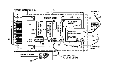
Referring to FIG. 1, there is shown a slot 10 for PCMCIA cards having an open
end 12
and a connector 14, such as a standard PCMCIA card connector, which may be a
female
connector, at the bottom of the slot. The slot may be in a miniature,
computerized device, such
as a computer terminal, laptop computer or other device which has PCMCIA card
slots.
A PCMCIA card 16 has at the inner edge (not shown) thereof a standard PCMCIA
card
connector 18. When the card 16 is inserted into the slot 10, the connector 18
engages the
connector 14 to provide connections to the computer of the computerized device
having the slot
CA 02329196 2000-10-18
WO 00/14496 PCT/US99/18963
10, as for example to the bus which is connected to the computer and carries
operating power and
signals.
The integrated spectrophotometer card has the advantage of a unitary
construction in which
the electro-optic module is completely enclosed as indicated by the dash line
19 with the exception
of the electrical connectors 18, optional power connector for power supply 40
and optical
interfaces to the spectrophotometer 24. The optical interfaces are preferably
fiber-optic
connectors 32 and 34. By completely enclosing the electro-optic module, the
system is especially
suitable for use in which it is swapped in and out of computer 10. The
enclosure protects against
mechanical and electrical damage when the card is being handled or stored
outside of the
computer 10. The preferred enclosure is a sheet metal or plastic enclosure
which wraps in
circumferential manner around the card and its integrated with the connector
18 and the optical
interface of spectrophotometer 24. The outside dimensions of this enclosure
are with the
PCMCIA standards.
At the front edge 20 of the card 16, and preferably projecting out of the open
end 12 of
the slot 10 is a spectrophotometer 24. The spectrophotometer 24 is preferably
integrated into the
card 16 to provide a unitary structure package to have a form factor
compatible with the
dimensional standards for a PCMCIA card. This spectrophotometer is shown
generally in FIG.
1 as having an optical section 26 and a detector array 28, which may be
enclosed by a cover 27.
An optical fiber connector 30 brings light in from an optical fiber 32 (FIG.
1) to the
spectrophotometer. This optical fiber may be a dual channel fiber optic cable,
wherein a fiber
34 carrying illumination from a lamp 36 mounted on the card 16 is part of the
cable. The lamp
is operated by a lamp circuit 38 to receive power via the bus and connectors
14 and 18 from the
computerized device which receives the card. The lamp 36 and circuit 38 and
card are integrated
with each other as part of the unitary structure with the spectrophotometer
24. A DC power
supply 40 which may be a piece of equipment external of the computerized
device may be used
to provide power for steady illumination, as an alternative from the power
coming from the
computerized device itself, and being connected to the lamp circuit 38, as via
the bus. In the
event that an emissive sample is to be spectrally measured, the lamp 36 need
not be energized.
CA 02329196 2000-10-18
WO 00/14496 PCT/US99/18963
-5-
If only emissive devices are to be tested, then the lamp 36, the lamp circuit
38 and the dual
channel of the fiber 32, 34 need not be used.
Referring to FIGS. 2 and 3, the optical section 26 may receive light from the
optical fiber
which is directed to a reflecting diffraction grating 42, which has focusing
power. Other gratings
and lens arrangements can be adapted to provide spectral dispersion and
optical focusing. The
light may arrive from the fiber 32 at the corner of a light pipe 44 or be
transmitted through a
partially transmissive mirror 46. The mirror bends the diffracted light and
directs it through an
aperture 48, preferably to an optical filter 50 which excludes wavelengths out
of the range of
interest (for example, the range of interest may be the visible range from
about 380 to about 750
microns) to a linear array of photodetectors 52, which may be a CCD (charge
coupled device)
photodetector array or other linear photodetector array. Different spectral
components are
measured by the photodetectors along the array. Since the light is dispersed
by the grating and
focused across the linear photodetector array, the spectral components at one
end of the
wavelength band are received by photodetectors at one end of the array while
spectral components
at the opposite end of the wavelength band are received at the opposite end of
the array. It will
therefore be apparent that the spectrophotometer system is integrated with the
PCMCIA card as
a unitary structure. This integrated construction is a feature of the present
invention.
The signals from the detector array 52, are applied to an array processor 54.
The
processor controls the transmission of the signals corresponding to the
spectral components from
each photodetector of the array in a specified time sequence. The signals are
applied via the
processor 54 or directly to a microprocessor 56 which may be associated with
memory 58. The
memory 58 may contain RAM memory for data storage and non-volatile memory
which contains
the program for operating the microprocessor. A program for digitizing the
signals so as to
provide high resolution is discussed in U.S. Patent 5,568,143, issued to R.J.
Hutchison, et al. on
October 22, 1996 may be implemented in the microprocessor under the control of
data from the
memory 58.
A communications interface 57 is connected between the microprocessor and
lines Ll
through LP to the contacts of the connector 18 so as to provide the spectral
information to the
CA 02329196 2000-10-18
WO 00/14496 PCT/US99/18963
-6-
computerized device having the PCMCIA slot 12. The interface also obtains
operating commands
from the computerized device and forwards them to the microprocessor to
control the gathering
of spectral data.
Referring to FIGS. 4 and 5, there is shown another PCMCIA card 60 where the
spectrophotometer and all of the other circuit elements shown on the card and
described in
connection with FIG. 1 above may be incorporated into an opto-electronic ASIC
(application
specific integrated circuit) 61. This ASIC is mounted on the card 60 and is
indicated as
spectrophotometer system 62. Fiber optic connectors 64 and 66 connect a dual
channel fiber optic
cable 68 to an end thereof which may illuminate and receive signals from the
object of interest.
The spectrophotometer system 62 may be considered as embedded in the PCMCIA
card
or ASIC.
The circuitry from the mufti-element sensor array 70, which is part of the
ASIC and also
contains the linear array photodetectors provides timed signals via an array
processor 72 to an
analog to digital (A/D) converter 74. Signal conditioning in a signal
conditioner amplifier or
integrator, as in the above-referenced Hutchison patent, may be provided, if
desired. The spectral
signal to the A/D converter may be successive signals which correspond to
successive wavelength
increments or components. These signals are converted in the A/D converter 74
and applied to
the microprocessor controller 78. The controller also operates the lamp driver
circuit 80, either
continuously or upon command, to drive the illuminating lamp 82. The
microprocessor controller
is interfaced with the computerized device utilizing the PCMCIA
spectrophotometer by a
communications .interface circuit 84. All of the circuits 70 through 84 are
contained in the ASIC.
Referring to FIGS. 6 and 7, there is shown another PCMCIA card 90 similar to
the card
16. This card also includes a spectrophotometer system ASIC 92, incorporating
the detector
array, lamp driver, processing electronics and range finder electronics. Fiber
optic connectors
94 and 96 provides for transmission of the illumination and spectral signals
from and into a fiber
optic cable 98 as discussed above.
The spectrophotometer card 90 also has a range finder section 100 with
transmitting and
receiving ultrasonic transducers 102 and 104. These transducers receive a
drive signal, for
CA 02329196 2000-10-18
WO 00/14496 PCT/US99/18963
_7_
example generally a pulse train 106, from a driver 108 which is turned on and
off by a dedicated
controller or the microprocessor controller 110. This microprocessor
controller is similar to the
controller 98 but provides signals for turning on the transducer driver 108
and receiving range
signals from a phase discriminator 112. The phase discriminator measures the
time difference
in terms of the phase relationship of the transmitted or incident pulse train
106 and a reflected
pulse train 114, is corresponding to a signal from the input transducer 104.
Amplifier 116
increases the amplitude of the reflected signal to an appropriate level for
input to the phase
discriminator. The microprocessor controller translates the time difference
signal into a range
signal which is displayed or recorded, and may provide information as to the
dimensions of the
specimen or object which is being sampled for its spectral constituents, and
the dimensions of the
environs. The dimensions of the object under test may be obtained and, in the
event that the
spectrophotometer is used in the decoration of a room with wall covering or
paint of desired
colors, the size of the room and even the amount of paint can be computed by
programs in the
microprocessor 56 or its memory 57, or in the host, which may use
trigonometric equations; these
features being invoked via the host to which the card is connected.
Variations and modifications in the herein described system will undoubtedly
suggest
themselves to those skilled in the art. Accordingly the foregoing description
should be taken as
illustrative and not in a limiting some.