Note : Les descriptions sont présentées dans la langue officielle dans laquelle elles ont été soumises.
CA 02330737 2001-O1-10
P.7012/SO/Pa
Sulzer Pumpen AG, CH-8404 Winterthur (Switzerland
Flow machine for a fluid with a radial sealing gap between stator parts
anr~ a rntnr
The invention relates to a flow machine for a fluid, comprising a radial
sealing gap between stator parts and a rotor, with a self supporting
wear ring, of which the outer jacket surface is provided with a wear
surface and which is axially fixed in the direction of the axis of rotation
of the rotor, being provided at the sealing gap.
In flow machines, radial sealing gaps which are axially flowed through
frequently arise between the rotating parts and the stator parts and
must be kept small in order to keep leakage losses low. Many fluids are
provided with solid parts which can lead to abrasive wear in such
narrow sealing gaps. This is caused on the one hand by the rotation of
the rotor and on the other hand by a pressure difference which is
effective over the sealing gap in the axial direction. A widening of the
sealing gap increases the loss flow and reduces the volumetric
efficiency.
Up to a certain quota of solid parts one resorts to coating the surfaces
in the sealing gap with a wear resistant protective coating, the lifetime
of which is given through the nature of the operation. When the repair
intervals become too short, therefore, there remains only the use of self-
supporting wear rings of ceramic materials. These admittedly have a
very high wear resistance, but are however constructionally difficult to
handle, since they are rather brittle and can be manufactured only in
CA 02330737 2004-07-23
26380-70
-2-
simple shapes due to their wear resistance. A further
disadvantage in comparison with other materials consists iu
their insufficient coefficients of thermal expansion in
connection with their low elasticity, which represents a
risk for the operator of a flow machine, such as for example
a multistage radial pump, when a wear ring is stretched at
its inner side. Temperature fluctuations in the flow
medium, but also certain operating situations such as the
forwarding against a closed slider, which can likewise lead
to a temperature increase, can lead to impermissible tension
stresses in a wear ring of this kind.
In a wear ring which is stretched at its outer
jacket surface and the wear surface of which lies on the
inner side, a lowering of the temperature results in a
uniformly distributed increase of the compression stress,
which is as a rule permissible. If rather higher
temperatures are operated at, the outwardly held wear rings
can be held in a shrink connection, which in spite of the
greater thermal expansion of a holding metal part is still
sufficient for the centering and the force transfer. The
situation is different in wear rings which are provided with
a wear surface on their outer jacket surface.
The object of the invention is to make wear rings
with low coefficients of thermal expansion which are
provided on their jacket surface with a wear surface ,~n
order to make them usable for flow machines in a larue
range.
The invention provides a flow machine for fluid
comprising stator parts and a rotor separated by a sealing
gap, and a wear ring disposed in the sealing gap and having
an inner jacket surface and an outer jacket surface, the
CA 02330737 2004-07-23
26380-70
-3-
outer jacket surface being provided with a wear surface, the
wear ring being axially fixed in a direction of an axis of
rotation of the rotor, being made of a material with a lower
coefficient of thermal expansion than parts on which it is
supported, and lying hollowly on its inner jacket surfa~:e
when the temperature at the sealing gap is below a spe~i_-i~~
temperature, the wear ring being held in place by first anc~
second conical holder surfaces which converge towards the
axis of rotation and meet at a common apex on the axis of
rotation.
The invention also provides a flow machine for a
fluid comprising stator parts and a rotor separated by a
sealing gap, a counter ring disposed in the sealing gap and
having an inner jacket surface provided with a wear surface,
the counter ring being axially fixed in a direction of an
axis of rotation of the rotor, being made of a material wi-~h
a lower coefficient of thermal expansion than parts on whi~.~'~
it is supported, and lying hollowly on its outer ;,ackeT
surface at lower temperatures which occur at the sea's-'-:a
gap, the counter ring being held in place by first and
second conical holder surfaces which converge in a directi~~n
towards the axis of rotation and meet at a common apex on
the axis of rotation.
The invention further provides a flow machine for
fluid comprising stator parts and a rotor separated by a
gap, the rotor being rotatable about an axis of rotation,
and a wear ring disposed in the gap and having an outer
jacket surface provided with a wear surface, the wear ring
being fixed in an axial direction of the rotor, being made
of a material with a lower coefficient of thermal expansion
than parts on which it is supported, and having an inner
jacket surface that is out of contact with the parts
CA 02330737 2004-07-23
26380-70
-3a-
supporting it when the temperature at the gap is below a
predetermined temperature, the ring being held in place by
first and second conical holder surfaces each of which
converges towards the axis of rotation and forms an apex on
the axis of rotation.
The invention further provides a flow machine for
fluid comprising a stator and a rotor rotatable about an
axis of rotation, the stator and the rotor forming an
interface with a sealing gap through which fluid flowing
through the machine can leak, the sealing gap being defined
by a counter surface connected with one of the stator and
the rotor and a wear ring connected with the other one of
the stator and the rotor and having a wear surface opposite
the counter surface and spaced therefrom by the sealing gap,
the wear ring being constructed of a material having a
coefficient of thermal expansion which is smaller than a
coefficient of thermal expansion of material of which one of
the stator and the rotor to which the wear ring is connected
is constructed, the wear ring being dimensioned and arranged
so that a surface thereof which faces in a radial direction
is spaced from the one of the stator and the rotor to which
it is connected by another gap when the wear ring is at a
relatively low operating temperature and the other gay
substantially disappears at a pre-established highest
operating temperature, the one of the stator and the rotor
to which the wear ring is connected including a connector
for securing the wear ring thereto so that a more rap:~~~
expansion of the one of the stator and the rotor tc wl-.icr~
the wear ring is connected relative to the wear ring as the
temperature increases towards the pre-established highest
operating temperature causes a reduction in the size of the
other gap and prevents an excessive tension increase in the
wear ring.
CA 02330737 2004-07-23
26380-70
-3b-
The invention further provides a method of
operating a flow machine for a fluid comprising providing a
stator part and a rotor part of the flow machine, separating
the stator part and the rotor part by a sealing gap,
rotating the rotor about an axis of rotation, mounting a
wear ring on one of the stator part and the rotor part= so as
to prevent movement of the wear ring in the direction of the
axis of rotation, providing the wear ring with a wear
surface facing the sealing gap, selecting a material For one
wear ring that has a lower coefficient of thermal expa~:s:.cer~
than one of the stator part and the rotor part to which ~.he
wear ring is connected, holding the wear ring in place with
first and second conical holder surfaces each of which
converges toward the axis of rotation and forms an apex on
the axis of rotation, forming a spacing between radially
facing, opposing surfaces of the wear ring and the one of
the stator part and the rotor part to which the wear :ring is
connected permitting relative radial movements between the
wear ring and the one of the stator part and the rotor part
to which it is connected due to thermal expansion until a
predetermined temperature is reached, providing a fluid to
be flowed through the flow machine, and entraining soli~,~s vr,
the fluid before the fluid enters the flow machine.
This arrangement has the advantage that the
conical holder surfaces, which expand to a greater extent
than the wear ring when the temperature increases, expand
along their cone jacket lines relative to the wear ring. If
the axial bias force on the cone surfaces is not chosen too
large - the wear ring also expands somewhat - then a minimum
sliding movement between the conical surfaces can take
place, which prevents excessive ring tensions in the form of
tension stresses in the wear ring. With a straight shoulder
as holder surface this minimum sliding movement is likewise
CA 02330737 2004-07-23
26380-70
-3c-
possible. In the frictionless state a straight shou'der
with an oppositely lying cone surface would also effect a
centering of the wear ring with falling temperature. Due to
the friction it can therefore be advantageous to
additionally attach to the side of the straight shoulder an
outer centering shoulder, the shrinking tension of which is
still permissible at the lowest arising temperatures. In
this way an exact centering at the straight shoulder in each
temperature cycle is achieved.
This construction shows advantages in wear rings
with a coefficient of thermal expansion a of less than
10 x 10-6 degrees C. Wear rings of highly wear resist~_~nt
material such as ceramics, for example metal oxides,
tungsten carbide or silicon carbide, can be used in this
way.
CA 02330737 2001-O1-10
-4-
Even fluids with larger solid components can be forwarded. In this the
diameter of individual solid parts can have the size of the gap width of
the sealing gap, since a kind of grinding process for these large parts
arises due to the choice of the wear rings. This process has a favorable
effect at high operating temperatures above 100°C and/or above
300°C,
since ceramic materials change their wear properties only at much
higher temperatures.
In the following the invention will be described with reference to
exemplary embodiments. Shown are:
Fig. 1 schematically from the prior art, a section of a double-flow
pump with wear rings which are shrunk in at rotors and
stator parts;
Fig. 2 schematically, a section from Fig. 1, in which the leakage
flows through the radial sealing gaps are illustrated;
Fig. 3 schematically and enlarged, a first embodiment in
accordance with the invention for a wear ring at a rotor;
Fig. 4 schematically and enlarged, a further embodiment in
accordance with the invention at a rotating sleeve;
Fig. S schematically and enlarged, a further embodiment in
accordance with the invention with two conical holder
surfaces;
Fig. 6 schematically and enlarged, a further embodiment in
CA 02330737 2001-O1-10
-5-
accordance with the invention at a stationary sleeve; and
Fig. 7 schematically, a further embodiment in accordance with the
invention with two conical holder surfaces.
In the figures, self supporting wear rings la, lb for flow machines with
a fluid are shown, which are arranged at a radial sealing gap 18 to a
rotor 9 and of which the outer jacket surface 3 is provided with a wear
surface 2. The wear rings la, lb, which are fixed in the axial direction,
consist of a material with a lower coefficient of thermal expansion than
their support and lie hollowly on their inner jacket surface, with a first
conical holder surface 8 encountering with the apex of its cone a second
holder surface 8", which is designed as a straight shoulder, in the plane
19 of the latter on the axis of rotation or with a second holder surface,
which is designed as a conical holder surface 8', encountering the axis
of rotation 20 at its cone apex.
In the following figures, the same reference symbols will be used for
similar functional parts.
In Fig. 1 a known arrangement of a double-flow radial pump with closed
rotors 4, 14, a housing 10 and stator parts 12a, 12b, 12c, 12d is
shown. An inlet flow 15 flows through a first rotor 4, experiences a
pressure increase and is conducted via a deflection passage 21 to a
second rotor 14, and then after a further pressure increase leaves the
housing 10 as outlet flow 17 via an outlet spiral 16. The rotor 9 with
axis of rotation 20 is assembled from a shaft 11, rotors 4, 14 and shaft
sleeves 22a, 22b, 22c, 22d. Bearings and housing seals are not shown.
CA 02330737 2001-O1-10
-6-
Radial sealing gaps 18 are produced with shrunk in wear rings at the
cover disc of the rotors 4, 14. In the first rotors 4, further sealing gaps
18 are provided behind the rotor at the hub side.
The enlarged section in Fig. 2 shows leakage flows 25, 24, 23, which
flow back in accordance with the pressure gradient between the rotor 9
and the stator parts 12c, 12d. The back-flow amount is determined
through the gap width of the radial sealing gaps 18. The latter consist of
a counter ring 26 which is shrunk in in a stator part 12c, 12d and of a
wear ring 1 a, 1 b which is secured on the rotating part 4, 14 and of
which the outer jacket surface is formed as a wear surface.
In Fig. 3 the wear ring la is provided on its outer side with a cylindrical
jacket surface 3 which is at the same time formed as a wear surface 2.
The inner cylindrical jacket surface lies hollowly and forms a gap S to
the rotor 4. The wear ring is supported in the axial direction at an end
surface by a holder surface in the form of a straight shoulder 8" which
is perpendicular to the axis of rotation 20. On the opposite side a holder
ring 5, which is in turn centered at the rotor 4 and is held by screws 6,
presses the wear ring la with a conical holder surface 8 in the axial
direction. The conical surface 8 belongs to a cone with half cone angle (3,
with the apex of the cone encountering a plane 19, in which the straight
shoulder 8" lies, on the axis of rotation 20. In addition to the friction of
the holder surfaces 8, 8", a rotational securing 13 in the form of a pin
which lies in a groove of the wear ring 1 a can transfer torque from the
rotor 4 to the wear ring.
CA 02330737 2001-O1-10
If it is assumed that the lowest operating temperature is present in the
shown position, then the gap S should be dimensioned in such a
manner that the gap S disappears at a specific operating temperature
as a result of the greater thermal expansion of the rotor without
impermissible tension stresses arising in the wear ring la at the highest
operating temperature.
If the plane 19 of the straight shoulder 8" is taken as a starting basis in
order to describe the movement during an increasing heating up of a
point P which is common to the holder surface 8 and the wear ring la,
then the holder ring 5 expands in the axial direction proportionally to
L x OT X aL, with L being the distance from the plane 19, 0T the
difference in temperature in degrees Celsius and aL the coefficient of
thermal expansion of the rotor 4. At the same time the holder ring
expands relative to the axis of rotation 20 in the radial direction
proportionally to R X 0T X aL, with R being the radial distance from the
point P. The rising of the point P thus amounts to:
RxOTxaL R
= tan ,(3 = constant
LxOTxa~ L
Analogously the rising of the original point P can be determined for the
wear ring 1 a with a coefficient of thermal expansion av:
RxOTxa'. R
= t~~3= constant
LxOTxa~, L
CA 02330737 2001-O1-10
This means that the holder surface 8' and the wear ring which is held
by it move with different speeds on the same conical surface with the
half cone angle ~3. If the friction between the holder surface 8 and the
wear ring la is dimensioned such that in the more rapid expansion of
the holder ring and the rotor no impermissible tension stresses arise in
the wear ring, then there exists a fixing which permits the temperature
dependent displacement between the holder ring 5 or the rotor 4,
respectively, and the wear ring. It is thus sufficient to design the holder
screws 6 for example as necked-down bolts and tighten them in such a
manner that no excessively large frictional forces can arise. A further
aid in the mounting of the wear ring 1 a consists in an additional
centering shoulder 7 which lies in contact at the outer jacket surface 3
of the wear ring at low temperatures and departs from it at increasing
temperatures. As long as the angle (3 is not chosen to be too close to
90°, a continuous centering of the wear ring la on the holder surface 8
of the holder ring 5 takes place.
In Fig. 4 the length L of a wear ring lb in relationship to the radial
distance R is chosen to be greater than in Fig. 3. In this the half cone
angle (3 becomes smaller and a better centering through the holder
surface 8 takes place. Simultaneously with the improved centering a
greater tension stress also arises in the wear ring lb. The pressing force
on an oppositely lying holder surface 8" of a holder ring 5 must
therefore be matched to the spreading action of the cone.
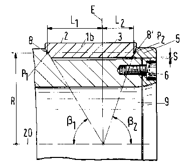
In Fig. 5 the length of the wear ring 1 b is composed of two sub-lengths
L1 and L2. Since the sum L1 + L2 corresponds approximately to the
CA 02330737 2004-07-23
26380-70
_g_
This means that the holder surface 8 and the wear ring which is held
by it move with different speeds on the same conical surface with the
half cone angle Vii. If the friction between the holder surface 8 and the
wear ring la is dimensioned such that in the more~rapid expansion of
the holder ring and the rotor no impermissible tension stresses arise in
the wear ring, then there exists a fixing which permits the temperature
dependent displacement between the holder ring 5 or the rotor 4,
respectively, and the wear ring. It is thus sufficient to design the holder
screws 6 for example as necked-down bolts and tighten them in such a
manner that no excessively large frictional forces can arise. A further
aid in the mounting of the wear ring 1 a consists in an additional
centering shoulder 7 which lies in contact at the outer jacket surface 3
of the wear- ring at low temperatures and departs from it at increasing
temperatures. As long as the angle (3 is not chosen to be too close to
90°, a continuous centering of the wear ring la on the holder surface 8
of the holder ring 5 takes place.
In Fig. 4 the length L of a wear ring lb in relationship to the radial
distance R is chosen to be greater than in Fig. 3. In this the half cone
angle ~ becomes smaller and a better centering through the holder
surface 8 takes place. Simultaneously with the improved centering a
greater tension stress also arises in the wear ring 1 b. The pressing force
on an oppositely lying holder surface 8" of a holder ring S must
therefore be matched to the spreading action of the cone.
In Fig. 5 the length of the wear ring lb is composed of two sub-lengths
L1 and La. Since the sum Li + L2 corresponds approximately to the
CA 02330737 2001-O1-10
_g_
radial distance R, well centering half cone angles y and ~i2 are created.
In relation to a theoretical separation plane E which is perpendicular to
the axis of rotation 20 and passes through the intersection of the two
cone apexes, two oppositely lying points P1 and P2 move in the holder
surfaces 8 and 8' with increasing temperature at the same radius on the
respective conical surface.
There are constructional restrictions in which the length of the wear
ring must be chosen substantially smaller than the radial distance R of
the holder surfaces 8, 8'. Nevertheless it is possible to achieve a good
centering, i.e. half cone angles X31, (32 of similar size for the wear ring lb
if the point of contact of the two cone apexes is displaced relative to the
wear ring on the axis of rotation 20 in a direction such as is shown in
Fig. 7. There the theoretical separation plane E lies outside the wear
ring. The effective length of the wear ring 1 b results from the difference
L2 - Li. The wear ring lb experiences a ring stress which is a
compression stress through the holder surface 8 with the larger half
cone angle (3i and a ring stress which is a tension stress through the
holder surface 8' with the half cone angle ~i2. The points P1 and P2 of the
holder surfaces move along the cone surfaces in temperature
fluctuations.
In Fig. 6 a wear ring 1 b is centered and secured analogously to Fig. 4,
with the holder ring 5 and a stator part 12b, at which a sleeve is molded
on, forming non rotating holder surfaces 8 and 8". A rotating counter
ring 26 is held at the rotor 4 with holder screws 6'. This counter ring 26
can likewise consist of a ceramic and have conical holder surfaces, the
CA 02330737 2001-O1-10
- 10-
cone apexes of which make contact on the axis of rotation 20. In
temperature increases, the rotor 4 and the holder ring 5' run off
outwardly more rapidly with respect to the counter ring 26 on the cone
surfaces with half cone angle yi, 'ya, and a gap arises at the outer jacket
surface of the counter ring. Nevertheless a reasonable centering of the
counter ring via the half cone angles yi, Y2 is possible. At very large
temperature differences or much greater coefficients of thermal
expansion of the rotor 4 and the holder ring 5' relative to the counter
ring 26, this is likewise a conceivable solution, if the counter ring 26
can not remain shrunk in over the entire temperature range.