Note : Les descriptions sont présentées dans la langue officielle dans laquelle elles ont été soumises.
CA 02331168 2004-11-24
- 1 -
FLEXIBLE GAS-FIRED HEAT EXCHANGER SYSTEM
FIELD OF THE INVENTION
The present invention relates to a compact, highly
flexible and efficient, multi-positionable, multi-
dimensional and multi-stage gas-fired heat exchanger system
for use in a forced air duct. The heat exchanger utilizes a
cascaded array of serpentine heat transfer tubes.
Particularly, but not exclusively, the heat exchanger of the
present invention was conceived to replace existing oil-
fired or electric forced air heating systems and designed as
a replacement thereof. Accordingly, the heat exchanger
system of the present invention is adaptable to existing
duct regardless of the size and orientation of the duct.
BACKGROUND OF THE INVENTION
It is very difficult to substitute a gas heater
for an electric hot water or oil-fired heater, as this
requires a restructure of the existing ductwork.
Accordingly, these conversions are extremely costly and not
very practical and popular. However, there exists a
commercial need to convert.
There is on the marketplace a multitude of gas
heaters but these are all of substantially standard
dimensions and installed in air convection ducts. There is
no gas-fired heating equipment on the market today that can
be used to economically and efficiently convert an electrip
heating system to gas. The problem is that the heating
equipment are of fixed dimensions, cumbersome and require
large installation space. The installation of the equipment
is also difficult as it must always be installed horizontal
and this requires extensive modification to the ventilation
ducts. Also, existing gas heaters need to be mounted
horizontal as electric equipment does not. Another problem
with gas heaters is that the gas supply as well as the
CA 02331168 2001-01-16
- 2 -
exhaust gas fumes are very cumbersome and do not provide
much flexibility to the installer.
An example of a gas-fired heater used in a forced
air system is illustrated and described in U.S. Patent
5,368,010. It is a fixed system and it is located in a
furnace unit which is supported on a floor located at the
base of the ductwork. This patent deals primarily with the
evacuation of combustion gases at the outlet of the heat
exchange tubes. Reference is also made to U.S. Patent
5,042,453, 5,094,224 and 4,729,207 as other examples of gas-
fired heaters used as a furnace associated with an air
convection duct system.
SUMMARY OF THE INVENTION
It is a feature of the present invention to
provide a compact, highly flexible and efficient, multi-
positionable, multi-dimensional and multi-stage gas-fired
heat exchanger system which is adaptable to existing forced
air ducts, and which substantially overcomes the above-
mentioned disadvantages of the prior art.
Another feature of the present invention is to
provide a gas-fired heat exchanger system as above-described
which is easy to install in existing air ducts regardless of
the size of the duct and the angular position thereof.
Another feature of the present invention is to
provide a gas-fired heat exchanger system as above described
and which can be used to readily replace existing electric
heaters which are more costly to operate.
Another feature of the present invention is to
provide a gas-fired heat exchanger system as above described
and which is constructed in accordance with parameters of
existing air ducts and wherein the physical characteristics
of the construction can be determined by way of a dedicated
computer software.
Another feature of the present invention is to
provide a gas-fired heat exchanger system as above described
comprising a plurality of gas heaters and wherein the gas
CA 02331168 2004-11-24
- 3 -
heaters can be modulated to adjust the heating capacity from
about 5% to 100%.
Another feature of the present invention is to
provide a gas-fired heat exchanger system as above described
and wherein the main component parts of the system are all
accessible on a support panel which is located exteriorly of
the convection ducts and easily accessible.
Another feature of the present invention is to
provide a gas-fired heat exchanger system as above described
and wherein a novel turbulator is used within the heat
transfer tubes to increase the efficiency of the heat
exchanger.
Another feature of the present invention is to
provide a gas-fired heat exchanger system as above described
and wherein the flue combustion gases can be evacuated
regardless of the position of the heat exchanger and by
simple means.
Acdording to the above features, from a broad
aspect, the present invention provides a compact, highly
flexible and efficient, multi-positionable and,
multi-dimensional gas-fired multi-stage heat exchanger system
for use in a forced air duct. The heat exchanger comprises
two or more heat transfer tubes. The tubes are provided in
numbers depending on the desired BTU/h capacity needs of the
heat exchanger. The tubes are secured to a support panel. A
gas burner is mounted on the support panel and disposed for
directing a flame at an inlet opening of an associated one of
the heat transfer tubes. A gas distribution manifold is
provided for supplying gas to the burners. A position
orientable modulating gas valve is secured to the manifold
and connectable to a gas supply line for controlling the gas
pressure to the burners and therefore the intensity of the
flame. The gas valve is disposed horizontal regardless of
the angular position of the system when secured to a duct.
Two or more solenoid valves are secured to the manifold and
to a respective one of the burners whereby to operate the
CA 02331168 2007-06-04
- 3a -
burners independently from one another. The tubes each have
an outlet connected to combustion product position orientable
exhaust means secured to the support panel. Control means is
provided to control the operation of the solenoid valves
whereby to operate the burners independently from one another
dependent on heat requirements. The control means controls
the temperature of the flame and the number of the burners
activated whereby to control the temperature of the heat
exchanger within the range of about 5% to 100%. The control
means further controls the speed of the exhaust fan in
combination with the burners to adjust convection flow
velocity.
CA 02331168 2001-01-16
- 4 -
According to a further broad aspect of the present
invention there is provided gas flow turbulence inducing
means associated with at least some of the tubes to cause
turbulence in a hot flue-gas flow in each of the tubes to
modify the efficiency in heat transfer along one or more
sections of the tubes by directing hot flue-gas along an
inner circumferential wall of the tubes.
BRIEF DESCRIPTION OF THE DRAWINGS
The preferred embodiments of the present invention
will now be described with reference to the accompanying
drawings in which
FIG. 1 is a perspective view illustrating a gas-
fired heat exchanger system of the present invention mounted
in an air duct of a forced air system;
FIG. 2 is a perspective view showing the basic
component part of the heat exchanger secured to a support
panel and utilizing U-shaped tubes;
FIG. 3 is a perspective view similar to Figure 2
but showing W-shaped serpentine tubes;
FIG. 4 is an exploded perspective view showing the
construction of the support panel and how the tubes are
securable thereto;
FIG. 5 is an exploded perspective view showing the
construction and associated attachments of the gas burners;
FIG. 6 is a front view of the gas distribution
manifold and solenoid valves;
FIG. 7 is a side view of Figure 6;
FIG. 8 is an enlarged view showing the
construction of the air/gas turbulator plate secured about
the inlet of the tubes in proximity of the gas burner
whereby to impart added turbulence to the flame;
FIG. 9 is a perspective view illustrating the
construction of the combustion product collection housing
and adjustable exhaust fan;
FIG. 10 is a side view of an elongated rectangular
metal plate utilized to construct the flue-gas turbulator;
CA 02331168 2001-01-16
- 5 -
FIG. 11 is a side view showing the construction of
the turbulator sections;
FIG. 12 is an end view of Figure 11 showing the
disposition of the sections;
FIG. 13 is an exploded perspective view
illustrating the mounting plate for mounting associated
hardware with the equipment mounted on the support panel;
FIG. 14 is an electrical diagram illustrating the
electric circuit utilized for a single stage heat exchanger;
FIG. 15 is an electrical diagram showing the
electric circuit for a multi-stage system;
FIG. 16 is an electrical diagram illustrating the
electric circuit for a modulated system; and
FIG. 17 is an exploded view of the entire heat
exchange system with its front housing and herein utilizing
U-shaped heat transfer tubes.
DESCRIPTION OF PREFERRED EMBODIMENTS
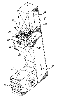
Referring now to Figure 1 there is shown generally
at 10 the compact, highly flexible and efficient, multi-
positionable, multi-dimensional and multi-stage gas-fired
heat exchanger system of the present invention and as herein
mounted in a forced air duct 11. An independent blower 12
circulates air from an air entry duct 13 through the multi-
stage heat transfer tubes 14 in the direction of arrow 15.
Referring now to Figures 2 to 4 there will be
described the basic component parts of the heat exchanger of
the present invention. As shown in Figure 2 the heat
transfer tubes 14 are U-shaped tubes and are secured at
opposed ends 16 and 16' to a support panel 17. The end 16
of the tubes 14, is the inlet end, and end 16' is the outlet
end. A plurality of gas burners 18, herein venturi type
burners are positioned in front the inlet end of the tubes
14 and direct a flame in each of the inlet end sections 16
of each tube. The gas burners 18 are secured to a gas
distribution manifold 19. A position orientable gas valve
20, which may be a single or two-stage or modulated valve,
CA 02331168 2001-01-16
- 6 -
is secured to the manifold and through its coupling 21 is
always positioned horizontally. For example, as shown in
Figure 1 the heat exchanger system 10 is herein shown as
being mounted sideways (horizontal) with the gas valve 20
having been positioned in the horizontal plane (90 to its
position shown in Fig. 3).
As more clearly shown in Figure 4 gas flow
turbulators 22 are disposed in the outlet end sections 16' '
of the tubes, herein a W-shaped heat transfer tube 14'
whereby to induce turbulence in the hot flue-gas flow in
each of the tubes to modify the efficiency in heat transfer
along the outlet section 16" . What the turbulators do is
to direct the hot flue-gas along the inner circumferential
wall of the tubes and there is virtually no gas flow along
the central longitudinal axis of the tubes in the outlet
section 16" where the turbulator is positioned. Although
not shown a turbulator section could also be positioned in
the inlet end section 16111 of the U-shaped tube 14 as shown
in Figure 2 but in an area space behind the flame of the
burners, which flame projects into the inlet end section of
these tubes. This would also increase the efficiency of the
heat transfer tubes.
As shown in Figure 3 the outlet end 16' of these
tubes 14, 14', which are secured to the support panel 17,
open in a collection housing 23 which receives combustion
gas from the tubes. An exhaust fan 24 is secured to an
outlet port 25 formed in an outer wall 26 of the housing 23
to create a suction within the collection housing to draw
the hot combustion products through the tube and to exhaust
the combustion products into a chimney duct 27. The exhaust
fan 24 has an adjustable shroud 28 which permits it to be
positioned at various angles depending on the desired
orientation of the chimney duct 27. Accordingly, regardless
of the position of the heat exchange system when secured in
a duct, the exhaust is flexible and permits the evacuation
of combustion products along any desired path or angle.
CA 02331168 2004-11-24
- 7 -
As shown in Figure 4 the support panel 17 is
provided with a plurality of pre-drilled holes 29 to mount
to the inlet and outlet sections of the tubes. The panel
also has internal flanges 30 to facilitate the connection of
the support panel to a front housing as will be described
later. It also provides for ease of location of a thermal
insulating sheet 31 over the front surface of the panel to
protect the panel against the intense heat of the flame of
the burners and the combustion products in the collection
housing 23. As also shown in Figure 4 an air/gas turbulator
plate 32 is securable over the holes 29 facing the burners.
With added reference to Figure 8 it can be seen
that the turbulator plate 32 is provided with an orifice 33
having inwardly extending deflector flanges 34 disposed side
by side all about the circumference of the orifice whereby
to increase turbulence at the inlet end opening 16 of the
tubes where the flame is injected. These deflector flanges
34 diminish the laminar secondary air flow and maximizes
thermal exchange with the tubes in the inlet end sections
thereof.
With reference now to Figures 5 and 6 there is
shown in greater detail the construction and mounting of the
burner assemblies. As previously described the burners 18
are venturi type burners and they have a predetermined heat
rate, such as, 17.5K BTU/h, 23.5K BTU/h, 30K BTU/h and 50K
BTU/h. A solenoid valve 35 is also associated with each of
the burners 18. These valves 35 are used to operate the
burners 18 independently by controlling the solenoids
whereby to control the heating capacity of the system from
about 5% to 100% of its total thermal heat exchange
capacity. These solenoids have a very quick response time
and are connected to the gas distribution manifold 19 by
threaded conduits 36 permitting quick assembly and
disassembly of the burner units for assembly, replacement or
repair. Nozzles 37 are also separately mounted between the
solenoid and the burners 18 and provide ease of assembly and
maintenance. The entire assembly is supported on the
CA 02331168 2001-01-16
- 8 -
support panel 17 by brackets 38. Accordingly, this assembly
can be pre-assembled and then secured to the support panel
17. The brackets 38 are secured to flanges 39 welded to
opposed ends of the manifold 19.
With reference now to Figures 10 to 12 there will
be described the construction of the turbulator 22. As
shown in Figure 10 the turbulator is constructed of an
elongated rectangular flat metal plate 40 which is cut from
opposed elongated edges 41 thereof to form opposed slits 42
whereby to form a plurality of deflection sections 43. The
deflection sections 43 are octagonally shaped as shown in
Figure 11 by bending the corner sections 44 in opposed
directions whereby to form deflection plate sections 43 of
octagonal contour. These deflection plate sections 43 are
also bent in the plane of the strip of the flat plate 40 at
angles of approximately 45 , as shown in Figure 12 to form a
twisted turbulator to force the combustion gas flow flowing
therethrough away from the center of the tubes 14 to an
inner surface 14' of the tubes, as illustrated in Figure 12.
The strip can also be cut at any desired length and
preferably between the deflection plate sections 43, at
areas such as illustrated by reference numeral 45, to fit in
a desired section of a tube. Accordingly, the turbulator
can have different quantities of deflection plate sections.
Although not shown, the sections 44 could be of different
sizes to create turbulation.
As shown in Figure 13 various components
as,sociated with the system are also mounted on a component
mounting plate 50 forwardly of the support panel 17. The
mounting plate 50 extends outwardly on a vertical axis
spaced from the burners 18 as can be seen in Figure 2. The
mounting plate assembly 50 is provided to mount associated
hardware and to make it readily accessible for servicing and
repair. As hereinshown an igniting control device 51 is
secured to the component mounting plate assembly and the
igniter 52 is secured to the side plate 50' at a position to
ignite the burners. An igniter cable 53 connects the
CA 02331168 2001-01-16
- 9 -
igniter 52 to the igniter controller 51. A flame detector
54 is also mounted on the side plate 50' and has a detector
cable 55 connected thereto, as is well known in the art. A
pressure detector 56 is also secured to the horizontal panel
50" and a detector tube 57 is connected thereto. A high
limit temperature detector 58 is also connected to the panel
50'. A voltage transformer 59 and a relay 60 are also
connected to the horizontal panel for ready access and
servicing.
With reference to Figure 17 there is shown the
construction of a support frame 61 which is secured to the
support panel 17. The support frame 61 comprises a bottom
and top wall 62 and 63 respectively secured to the top and
bottom internal flanges 30 of the front panel 17, and a rear
wall 64 secured between rear edges 62, and 63' of the bottom
and top plates 62 and 63, respectively. The top and bottom
and rear walls all have contour flanges which help to secure
same in an air duct such as the duct 11 as shown in
Figure 1, to orient the tubes for heat exchange with air
flow in the duct when a blower pushes air through the duct
for heating the convected air. The dimensions of the plate
are dictated by the cross-sectional dimension of the duct in
which the system is to be installed.
As also shown in Figure 17 the top and bottom
walls 63 and 62 are provided with air deflecting flanges 65
which project internally in the air flow to cause air
turbulence of the convected air in the area of the transfer
tubes to improve heat transfer between the tubes and
convected air. As also hereinshown the rear wall 64 is
provided with a vertical tube support flange 66 to support a
far end section of the heat transfer tubes to maintain them
in spaced parallel stack relationship. This flange is also
illustrated in Figure 4 and as shown in that Figure heat
exchange clamps 67 may also be secured to the tubes 14. The
heat exchange clamps are provided with a plurality of
projecting flanges 68 to dissipate heat into the air flowing
through the heat exchanger tubes. Preferably the heat
CA 02331168 2001-01-16
- 10 -
exchange clamps are secured to at least some of the tubes
along the inlet section thereof where the tubes are at a
higher temperature. As previously described these tubes may
be of U-shapes, W-shapes, square shapes or any other
suitable shapes for heat exchange with the convected air in
the duct and to suit the application.
As previously pointed out, the gas-fired heat
exchanger system of the present invention is customizable to
suit air ducts of different sizes and different capacity
requirements. To this end there has been developed a
computer software to calculate specific physical parameters
for the construction of the heat exchanger of the present
invention. The computer is inputted information relating to
the dimension of duct where the heat exchanger is required
to be installed as well as information relating to the
volume of air to be heated. Parameters of the static
pressure of the forced air system are also inputted in the
computer as well as the temperature of air to be convected
upstream of the heat exchanger. Also inputted is the
desired temperature required downstream of the heat
exchanger. This inputted information is analyzed and the
software produces physical parameters for the design of the
unit including the configuration of the heat transfer tubes,
the quantity of the tubes required, the diameter and length
of the tubes and the thermal capacity of the burners.
Accordingly, the size of the unit is adjustable whereby the
length of its side Ll, width L2, and height H, as shown in
Fig. 2, are variable.
As shown in Figures 1 to 4 and 17 the heat
transfer tubes 14 are all connected in stack parallel spaced
relationship and all attached to the support panel to
produce a compact package. In most instances the heat
exchanger will comprise a plurality of heat exchange tubes
and these can be controlled in a"multi-stage" application
as shown by the schematic electrical diagram in Figure 15 or
in a"modulated mode" as illustrated by the schematic
diagram of Figure 16. In the "multi-stage" application the
CA 02331168 2001-01-16
- 11 -
thermal capacity of the heat exchanger can be controlled by
switching on and off some of the burners thereby utilizing
only certain ones of the heat transfer tubes to satisfy the
heat demand. In the "multi-stage" mode the gas valve 20
could be a two-stage valve which permits a control of the
temperature in a range of from about 5% to 100% of its total
capacity. In that mode, with the two-stage valve 20 the
first burner is ignited at 50% of its maximum capacity and
later its capacity is increased to 100%. The other burners
are then ignited one after the other and this is how the
temperature control of the heat exchanger is varied.
In the "modulated mode" all of the burners
function at the same time, the modulation is obtained by the
principal valve 20 which is a modulated type valve. With
this valve the gas pressure to a1:1 of the burners is
modulated in accordance with the heat requirement. In this
mode the modulation of the maximum heat produced by the heat
exchanger can be varied between approximately 40% to 100% of
the maximum capacity of the heat exchanger.
Figure 14 is a circuit diagram for a single stage
heat exchanger capable of generating a predetermined heat
capacity which is non-variable.
As illustrated in Figures 2 and 3 the heat
exchange system 10 may be mounted at any desired position
along the X, Y or Z axis as illustrated by arrows 71, 72 and
73. Regardless of the positioning of the unit the gas valve
20 is adjusted to lie in a horizontal. plane. This is done
by using a suitable coupling 21 or simply rotating the gas
valve on the threaded end of the pipe coupling 21 depending
on the position of the unit. But this is predetermined by
the application.
As also shown in Figure 17 a protective housing 80
having an access panel 81 for access to the support panel 17
may also be provided. For security a lock could also secure
the front panel 81 to the housing. As hereinshown the front
panel 81 is provided with an air intake 82 to admit
combustion air to the burners. A gas line entry port 83 may
CA 02331168 2004-11-24
- 12 -
be provided on the front panel around the side and as
hereinshown is protected by a grommet 84. The exhaust fan
24 may also be secured to either the side walls 85 or top
and bottom walls 86 and 87 of the housing depending on the
position of the installation and the flue pipe.
Accordingly, there is provided a flexible extension tube 88
having couplings 89 at opposed ends thereof to connect the
collection housing 23 to the exhaust fan 24. The exhaust
fan 24 is also provided with a coupling 90 to secure to an
exhaust pipe and attaching flange and gaskets 91 and 92
respectively. An extension pipe 93 may also be secured to
the exhaust fan, if necessary.
Although the electric circuit diagrams of Figures
14 to 16 have not been described in detail it is only
necessary to describe that in the single stage application
the heat exchanger also operates in a single maximal heat
generating mode when the valve 20 is "on" to supply gas to
the burners.
In operation, the system is actuated by a heat
requirement on the low voltage created by the thermostat and
the system firstly monitors the safety equipment associated
therewith. The relay 60 then connects the gas, herein
natural gas, and upon detecting the gas pressure, the
ignition control commands the opening of the gas valve and
the igniter. As soon as the flame is detected by the flame
detector 54 the apparatus is in operation. Once the
thermostat sends the signal that the temperature has reached
its setting, the gas supply to the valve 20 is cut and the
burners extinguished.
In the modulating mode as illustrated by Figure 16
the pressure of the gas is modulated through a gas
modulating valve. In this particular application there is
provided a stack of heat transfer tubes. The gas modulating
valve can vary the temperature of the flame and therefore
heat exchanger between 40-1 and 100% of its maximum value.
The purpose of the burner modulation is to maintain the
temperature of the air to be heated substantially constant.
CA 02331168 2004-11-24
- 13 -
The gas modulating valve is controlled by a variable control
device 100 as shown in Figure 15. The control circuit is
illustrated by Figure 14.
With reference to Figure 15 there is shown the
multi-stage operation wherein each of the burners 18 is
controlled independently by the solenoid valves 35. The
burners are ignited, or not, one at a time to satisfy the
temperature demands. If the main gas valve is a two-stage
valve the first burner can be positioned to generate a low
temperature flame which is usually half of the maximal
intensity or at a high temperature flame. By controlling
the temperature of the flame and the number of burners that
are activated it is possible to control the temperature of
the heat exchanger within the range of about 5% to 100%, as
previously described. This way it is possible to provide a
more precise control of the air temperature for comfort. In
addition the speed of the exhaust fan 24 can be controlled
in combination with the burners by suitable control
circuitry.
It is within the ambit of the present invention to
cover any obvious modifications of the preferred embodiment
described herein, provided such modifications fall within
the scope of the appended claims.