Sélection de la langue

Search

Sommaire du brevet 2331173 

Énoncé de désistement de responsabilité concernant l'information provenant de tiers

Une partie des informations de ce site Web a été fournie par des sources externes. Le gouvernement du Canada n'assume aucune responsabilité concernant la précision, l'actualité ou la fiabilité des informations fournies par les sources externes. Les utilisateurs qui désirent employer cette information devraient consulter directement la source des informations. Le contenu fourni par les sources externes n'est pas assujetti aux exigences sur les langues officielles, la protection des renseignements personnels et l'accessibilité.

Disponibilité de l'Abrégé et des Revendications

L'apparition de différences dans le texte et l'image des Revendications et de l'Abrégé dépend du moment auquel le document est publié. Les textes des Revendications et de l'Abrégé sont affichés :

  • lorsque la demande peut être examinée par le public;
  • lorsque le brevet est émis (délivrance).
(12) Brevet: (11) CA 2331173
(54) Titre français: APPAREIL POUR TRAITEMENT A L'AIR DE PRODUITS
(54) Titre anglais: APPARATUS FOR AIR-TREATMENT OF PRODUCTS
Statut: Périmé et au-delà du délai pour l’annulation
Données bibliographiques
(51) Classification internationale des brevets (CIB):
  • F25D 13/06 (2006.01)
  • A23L 03/36 (2006.01)
  • B65G 17/06 (2006.01)
  • F25D 03/11 (2006.01)
  • F25D 25/04 (2006.01)
  • F26B 15/26 (2006.01)
(72) Inventeurs :
  • PAHLSSON, STEN (Suède)
(73) Titulaires :
  • FRIGOSCANDIA EQUIPMENT AB
(71) Demandeurs :
  • FRIGOSCANDIA EQUIPMENT AB (Suède)
(74) Agent: SMART & BIGGAR LP
(74) Co-agent:
(45) Délivré: 2007-05-15
(86) Date de dépôt PCT: 1999-05-04
(87) Mise à la disponibilité du public: 1999-11-11
Requête d'examen: 2004-01-08
Licence disponible: S.O.
Cédé au domaine public: S.O.
(25) Langue des documents déposés: Anglais

Traité de coopération en matière de brevets (PCT): Oui
(86) Numéro de la demande PCT: PCT/SE1999/000735
(87) Numéro de publication internationale PCT: SE1999000735
(85) Entrée nationale: 2000-11-02

(30) Données de priorité de la demande:
Numéro de la demande Pays / territoire Date
09/073,247 (Etats-Unis d'Amérique) 1998-05-06

Abrégés

Abrégé français

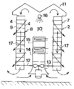
On décrit un appareil de traitement à l'air de produits. L'appareil comprend une bande transporteuse sans fin qui parcourt sur une partie de sa longueur un trajet hélicoïdal formant une pile étagée. Des plaques latérales situées sur un bord longitudinal de la bande transporteuse forment une paroi cylindrique extérieure qui délimite la pile radialement vers l'extérieur. Une paroi cylindrique intérieure délimite la pile radialement vers l'intérieur. Cette configuration crée un espace central entre la paroi cylindrique extérieure et la paroi cylindrique intérieure. Un obturateur d'extrémité aboute sensiblement la paroi cylindrique extérieure à une extrémité de la pile. Des moyens sont mis en place pour souffler de l'air à travers l'espace central vers l'obturateur d'extrémité puis retour à travers l'espace annulaire délimité par la paroi cylindrique extérieure et la paroi cylindrique intérieure, de manière à traiter à l'air des produits acheminés par la bande transporteuse dans le trajet hélicoïdal. L'air est conditionné et soufflé à travers l'espace annulaire délimité par la paroi cylindrique extérieure et la paroi cylindrique intérieure.


Abrégé anglais


An apparatus for air-treatment of products
comprises an endless conveyor belt following through
part of its length a helical path forming a stack of tiers.
Side plates at one longitudinal edge of the conveyor
belt form an outer cylinder wall delimiting the stack
radially outwards. An inner cylinder wall delimits
the stack radially inwards. 1'hereby, a central space
is defined by the inner cylinder wall and an annular
space is defined between the outer cylinder wall and
the inner cylinder wall An end closure substantially
adjoins the outer cylinder wall at one end of the
stack. Means are provided for blowing air through
the central space towards the end closure and back
through the annular space between the outer and inner
cylinder walls for air-treatment of products carried
by the conveyor belt in the helical path. The air
is conditioned and blown through the annular space
between the outer and inner cylinder walls.

Revendications

Note : Les revendications sont présentées dans la langue officielle dans laquelle elles ont été soumises.


8
CLAIMS
1. An apparatus for air-treatment of products,
comprising
an endless conveyor belt following through part of
its length a helical path forming a stack of tiers,
side plates at one longitudinal edge of the conveyor
belt forming an outer cylinder wall delimiting the stack
radially outwards, and
means forming an inner cylinder wall delimiting the
stack radially inwards,
whereby a central space is defined by the inner
cylinder wall and an annular space is defined between the
outer cylinder wall and the inner cylinder wall,
characterised by
a housing comprising a single peripheral wall. formed
by the outer cylinder wall and an end closure
substantially adjoining the outer cylinder wall at one
end of the stack,
means for blowing air through the central space
towards the end closure and back through the annular
space between the outer and inner cylinder walls for air-
treatment of products carried by the conveyor belt in the
helical path, and
means for conditioning the air blown through the
annular space between the outer and inner cylinder walls.
2. An apparatus as claimed in claim 1, wherein the
end of the central space opposite the end closure is
closed except for an inlet to the air-blowing means.
3. An apparatus as claimed in claim 2, wherein the
annular space between the outer and inner cylinder walls
is open at the end opposite the end closure.

9
4. An apparatus as claimed in claim 2 or 3, wherein
the conditioning means is positioned in the central space
within the inner cylinder wall.
5. An apparatus as claimed in claim 2 or 3, wherein
the conditioning means is positioned outside a room
having an inlet from the conditioning means and an
outlet.
6. An apparatus as claimed in claim 1, further
comprising a further end closure substantially adjoining
the outer cylinder wall at the other end of the stack,
whereby air is blown in a substantially closed path.
7. An apparatus as claimed in claim 6, wherein the
conditioning means is positioned in the inner space
within the inner cylinder wall.
8. An apparatus as claimed in claim 6, wherein the
conditioning means is positioned in the further end
closure.
9. An apparatus as claimed in claim 8, wherein the
further end closure comprises a chamber having a first
opening towards the annular space between the outer and
inner cylinder walls and a second opening towards the
central space within the inner cylinder wall.
10. An apparatus as claimed in claim 1, wherein the
side plates of an underlying tier of the stack support
the outer longitudinal edge of an overlying tier of the
stack.
11. An apparatus as claimed in claim 1, wherein the
conveyor belt has side plates at both of its longitudinal
edges forming said outer and inner cylinder walls.
12. An apparatus as claimed in claim 11, wherein the
side plates of an underlying tier of the stack support
the corresponding longitudinal edge of an overlying tier
of the stack.

Description

Note : Les descriptions sont présentées dans la langue officielle dans laquelle elles ont été soumises.


CA 02331173 2007-02-15
28569-11
1
APPARATUS FOR AIR-TREATMENT OF PRODUCTS
The present invention relates to air-treatment of
products, primarily food products and the like, using
appropriately conditioned air.
The prior art includes several types of apparatuses
for such treatment where the conditioned air is sub-
stantially different from the air surrounding the
apparatus. Therefore, it is important that the condi-
tioned air is recirculated within the apparatus, i.e. the
apparatus should be as air-tight as possible and this
often makes the apparatus complex and expensive.
When the difference between the conditioned air and
the surrounding air is not very extreme, a less compli-
cated apparatus would be preferable.
The object of the present invention is to provide a
simple and cost-effective apparatus for air-treatment of
products, such as cooling and proofing.
This object is achieved with an apparatus which
comprises an endless conveyor belt following through part
of its length a helical path forming a stack of tiers,
side plates at one longitudinal edge of the conveyor belt
forming an outer cylinder wall delimiting the stack
radially outwards, and means forming an inner cylinder
wall delimiting the stack radially inwards, whereby a
central space is defined by the inner cylinder wall and
an annular space is defined between the outer cylinder
wall and the inner cylinder wall. The apparatus further
comprises a housing comprising a single peripheral wall
formed by the outer cylinder wall and an end closure
substantially adjoining the outer cylinder wall at one
end of the stack, means for blowing air through the
central space towards the end closure and back through
the annular space between the outer and inner cylinder

CA 02331173 2007-02-15
28569-11
. 2
walls for air-treatment of products carried by the
conveyor belt in the helical path, and means for
conditioning the air blown through the annular space
between the outer and inner cylinder walls.
By this design, the outer cylinder wall also forms
the single peripheral wall of the apparatus which there-
fore does not need any separate housing. This means a
major cost reduction. The fact that the outer cylinder
wall may not form a perfect air-tight wall is of less
importance when the influence of the conditioning means
on the air, e.g. for heating or cooling the air or for
adjusting its humidity, is not very substantial.
In a first embodiment of the apparatus according to
the invention, the end of the central space opposite to
the end closure is closed except for an inlet to the air-
blowing means. Thus, air is sucked into the apparatus
from the environment by the air-blowing means and is
returned to the environment, preferably at an open end of
the annular space opposite to the end closure, after
having passed first through the conditioning means and
then through the annular space where the products to be
treated are carried by the conveyor belt along the
helical path. In this embodiment, the conditioning means
is positioned in the central space within the inner
cylinder wall.
Alternatively, the conditioning means may be posi-
tioned outside a room accommodating the apparatus,
wherein the room has an inlet from the conditioning means
and an outlet.
In a further embodiment, the apparatus comprises a
further end closure substantially adjoining the outer
cylinder wall at the other end of the stack, whereby air
is blown in a substantially closed path. In this embodi-

CA 02331173 2000-11-02
WO 99/57496 PCT/SE99/00735
3
ment, the conditioning means may be positioned in the
inner space within the inner cylinder wall or may be
positioned in the further end closure.
FIG. 1. is a schematic perspective view illustrating
a belt conveyor of the prior art.
FIG. 2-5 are schematic side views of four embodi-
ments of an apparatus for air-treatment of products
according to the present invention.
A belt conveyor of the type shown in FIG. 1 has a
conveyor belt 1 adapted to follow, in the manner illus-
trated, through part of its length a path comprising a
number of superimposed helically extending tiers forming
a stack 2. The illustrated conveyor belt 1 comprises a
number of mutually articulated links and can run straight
and in curves upwards, downwards and sideways.
Each link comprises a bottom part 3 and a spacer 4
at least at the outer longitudinal side 5 of the conveyor
belt 1, as seen in the stack 2. Each link may have a
spacer 4 also at the inner longitudinal side 6 of the
conveyor belt 1. The spacers 4 of an underlying tier in
the stack 2 engage and support the corresponding side
edge of an overlying tier. Thereby, the spacers 4 at the
outer longitudinal side of the conveyor belt 1 in the
stack 2 form an outer cylinder wall 7, and the spacers 4
at the inner longitudinal side of the conveyor belt. 1 in
the stack 2 form an inner cylinder wall 8, such that an
annular space 9 is formed betwe.en the outer cylinder wall
7 and the inner cylinder wall 8. A cylindrical central
space 10 is formed within the inner cylinder wall B.
As an alternative to the inner cylinder wall 8
formed by spacers 4, the inner cylinder wall may comprise
a wall separate from the conveyor belt 1, e.g. a wall
formed on the outer periphery of a drum used for suppor-

CA 02331173 2000-11-02
WO 99/57496 PCT/SE99/00735
4
ting the conveyor belt at its inner longitudinal side in
the stack.
In both alternatives, the annular space 9 is used as
a channel for blowing air past products carried by the
conveyor belt 1. Normally, the air is blown vertically
through the annular space 9 to cool or heat the products
or to change the moisture content of the products.
The alternative types of conveyor belts referred to
above are described more in detail in U.S. Patents Nos.
3, 938, 651; 4, 565, 282; 4, 875, 343; 4, 941, 567; 5, 031, 751;
and 5,226,291, which all are incorporated herein by
reference. Further, these conveyor belts may be combined
with several types of supporting and/or driving means
found in the prior art. Some of these supporting arid/or
driving means also are described in the above refei-enced
patents.
The above described conveyor belts may be used in an
apparatus for air-treatment of products according to the
present invention, as illustrated in FIGS. 2-5. In these
Figures, the conveyor belt 1 is illustrated very
schematically as a stack 2 of tiers and those parts of
the conveyor belt 1 which are outside the stack 2 are not
shown. Further, the conveyor belt used has preferably
spacers 4 at both longitudinal sides such that the stack
2 is self-supported except for the lowest tier.
The embodiment illustrated in FIG. 2 comprises the
stack 2 and a top cover 11 which constitutes an end
closure substantially adjoining the outer cylinder wall 7
at the top end of the stack 2. Further, a horizontal
partition 12 is positioned near the bottom of the central
space 10 adjoining to the inner cylinder wall B. This
partition 12 closes the central. space 10 at its lower end
except for an inlet to a fan 1-~, which constitutes a means

CA 02331173 2000-11-02
WO 99/57496 PCT/SE99/00735
for blowing air from outside the stack 2 upwards through
the central space 10 against the top cover 11 where the
flow of air is redirected down through the annular space
9 from the top end to the bottom end thereof. The annular
5 space 9 is open at its bottom end so that the air blown
through the annular space 9 can escape at that end. As
shown in FIG. 2, the air sucked in by the fan 13 is
passed through a cooler 14 and/or a heater 15 and/or is
passed by a steam generator 16 so as to condition the air
before its passing down through the annular space 9.
The above described configuration is useful when tne
required air velocity is not too high, e.g. less than
about 2 m/s, and also when the conditioning of the air to
be blown through the annular space 9 is not very sub-
stantial, e.g. the required ten,,.perature decrease/increase
generated by the cooler 14/heater 15 and/or the humidity
increase obtained through the steam generator 16. As
illustrated by arrows 17 directed from the inside of the
inner cylinder wall 8 through the stack 2 to the outside
of the outer cyli_nder wall 7 neither one of these walls 7
and 8 need to be perfectly tight. Thus, it is possible to
use a conveyor belt of the types described above being
self-supported at least at its outer edge in the stack 2
and, preferably, being self-supported also at its inner
peripheral edge in the stack 2.
The arrangement supporting the conveyor belt 1 and
the top closure 11 in FIG.1 is not illustrated but are
obvious to the man skilled in the art. However, it should
be noted that the stack 2 formed by the conveyor belt 1
is continuously revolving while! the top closure 11 is
stationary.
The embodiment illustrated in FIG. 3 differs from
the one illustrated in FIG. 2 in that a skirt 18

CA 02331173 2000-11-02
WO 99/57496 PCT/SE99/007.35
6
surrounds the lower end of the apparatus and forms a
closure adjoining the bottom end of the outer cylinder
wall 7 and the floor beneath the apparatus. Thereby, the
air blown up through the central space 10, down through
the annular space 9 and out of the bottom open end of the
annular space 9 is recirculated by being sucked into the
fan 13. Of course, this skirt 18 is much simpler and
cheaper than the housing normally used in the prior art
apparatus, as exemplified in the references cited above.
The embodiment illustrated in FIG. 4 uses double
skirts, i.e. a first skirt 19 corresponding to the skirt
18 in the embodiment illustrated in FIG. 3 and a second
skirt 20 adjoining the bottom end of the inner cylinder
wall 8 and the floor beneath the apparatus. As a result,
a chamber 21 is formed below the stack 2. This chamber 21
has a first opening that coincides with the bottom
opening of the annular space 9 and a second opening
towards the central space 10 within the inner cylinder
wall 8. More precisely, the fan 13 and the conditioning
means comprising a cooler 14 and/or a heater 15 ancl/or a
steam generator 16, are inserted between the second
opening and the lower end of the central space 10. As a
consequence of the opening in the chamber towards the
conditioning means, no partition is necessary at the
lower end of the central space 9.
Finally, FIG. 5 illustrates a further embodiment of
the apparatus according to the present invention which is
identical with the embodiment illustrated in FIG. 2
except that the conditioning means is positioned outside
a room 22 which accommodates the rest of the apparatus.
The room 22 has a bottom inlet 23 connected to the
conditioning means (not shown) and a top outlet 24 for
expelling surplus air.

CA 02331173 2000-11-02
WO 99/57496 PCT/SE99/00735
7
It goes without saying that the invention is not
restricted to the embodiments described above, and that a
variety of modifications is possible within the scope of
the invention as defined in thF! appended claims. Thus,
the means forming the inner cylinder wall may be separate
from the conveyor belt, e.g. comprise a central drum.

Dessin représentatif
Une figure unique qui représente un dessin illustrant l'invention.
États administratifs

2024-08-01 : Dans le cadre de la transition vers les Brevets de nouvelle génération (BNG), la base de données sur les brevets canadiens (BDBC) contient désormais un Historique d'événement plus détaillé, qui reproduit le Journal des événements de notre nouvelle solution interne.

Veuillez noter que les événements débutant par « Inactive : » se réfèrent à des événements qui ne sont plus utilisés dans notre nouvelle solution interne.

Pour une meilleure compréhension de l'état de la demande ou brevet qui figure sur cette page, la rubrique Mise en garde , et les descriptions de Brevet , Historique d'événement , Taxes périodiques et Historique des paiements devraient être consultées.

Historique d'événement

Description Date
Le délai pour l'annulation est expiré 2010-05-04
Lettre envoyée 2009-05-04
Accordé par délivrance 2007-05-15
Inactive : Page couverture publiée 2007-05-14
Exigences de modification après acceptation - jugée conforme 2007-03-07
Lettre envoyée 2007-03-07
Modification après acceptation reçue 2007-02-15
Préoctroi 2007-02-15
Inactive : Taxe de modif. après accept. traitée 2007-02-15
Inactive : Taxe finale reçue 2007-02-15
Un avis d'acceptation est envoyé 2006-09-06
Lettre envoyée 2006-09-06
Inactive : Approuvée aux fins d'acceptation (AFA) 2006-06-12
Inactive : CIB de MCD 2006-03-12
Lettre envoyée 2004-02-02
Requête d'examen reçue 2004-01-08
Exigences pour une requête d'examen - jugée conforme 2004-01-08
Toutes les exigences pour l'examen - jugée conforme 2004-01-08
Inactive : Page couverture publiée 2001-03-02
Inactive : CIB en 1re position 2001-02-27
Inactive : Notice - Entrée phase nat. - Pas de RE 2001-02-15
Lettre envoyée 2001-02-15
Demande reçue - PCT 2001-02-14
Demande publiée (accessible au public) 1999-11-11

Historique d'abandonnement

Il n'y a pas d'historique d'abandonnement

Taxes périodiques

Le dernier paiement a été reçu le 2007-02-01

Avis : Si le paiement en totalité n'a pas été reçu au plus tard à la date indiquée, une taxe supplémentaire peut être imposée, soit une des taxes suivantes :

  • taxe de rétablissement ;
  • taxe pour paiement en souffrance ; ou
  • taxe additionnelle pour le renversement d'une péremption réputée.

Les taxes sur les brevets sont ajustées au 1er janvier de chaque année. Les montants ci-dessus sont les montants actuels s'ils sont reçus au plus tard le 31 décembre de l'année en cours.
Veuillez vous référer à la page web des taxes sur les brevets de l'OPIC pour voir tous les montants actuels des taxes.

Historique des taxes

Type de taxes Anniversaire Échéance Date payée
TM (demande, 2e anniv.) - générale 02 2001-05-04 2000-11-02
Taxe nationale de base - générale 2000-11-02
Enregistrement d'un document 2000-11-21
TM (demande, 3e anniv.) - générale 03 2002-05-06 2002-04-23
TM (demande, 4e anniv.) - générale 04 2003-05-05 2003-04-16
Requête d'examen - générale 2004-01-08
TM (demande, 5e anniv.) - générale 05 2004-05-04 2004-03-17
TM (demande, 6e anniv.) - générale 06 2005-05-04 2005-03-14
TM (demande, 7e anniv.) - générale 07 2006-05-04 2006-03-15
TM (demande, 8e anniv.) - générale 08 2007-05-04 2007-02-01
2007-02-15
Taxe finale - générale 2007-02-15
TM (brevet, 9e anniv.) - générale 2008-05-05 2008-04-17
Titulaires au dossier

Les titulaires actuels et antérieures au dossier sont affichés en ordre alphabétique.

Titulaires actuels au dossier
FRIGOSCANDIA EQUIPMENT AB
Titulaires antérieures au dossier
STEN PAHLSSON
Les propriétaires antérieurs qui ne figurent pas dans la liste des « Propriétaires au dossier » apparaîtront dans d'autres documents au dossier.
Documents

Pour visionner les fichiers sélectionnés, entrer le code reCAPTCHA :


Pour visualiser une image, cliquer sur un lien dans la colonne description du document. Pour télécharger l'image (les images), cliquer l'une ou plusieurs cases à cocher dans la première colonne et ensuite cliquer sur le bouton "Télécharger sélection en format PDF (archive Zip)" ou le bouton "Télécharger sélection (en un fichier PDF fusionné)".

Liste des documents de brevet publiés et non publiés sur la BDBC .

Si vous avez des difficultés à accéder au contenu, veuillez communiquer avec le Centre de services à la clientèle au 1-866-997-1936, ou envoyer un courriel au Centre de service à la clientèle de l'OPIC.


Description du
Document 
Date
(aaaa-mm-jj) 
Nombre de pages   Taille de l'image (Ko) 
Dessin représentatif 2001-03-01 1 8
Description 2000-11-01 7 280
Revendications 2000-11-01 2 80
Dessins 2000-11-01 3 87
Abrégé 2000-11-01 1 63
Dessin représentatif 2006-06-12 1 9
Description 2007-02-14 7 283
Avis d'entree dans la phase nationale 2001-02-14 1 194
Courtoisie - Certificat d'enregistrement (document(s) connexe(s)) 2001-02-14 1 113
Rappel - requête d'examen 2004-01-05 1 123
Accusé de réception de la requête d'examen 2004-02-01 1 174
Avis du commissaire - Demande jugée acceptable 2006-09-05 1 162
Avis concernant la taxe de maintien 2009-06-14 1 171
PCT 2000-11-01 11 376
Correspondance 2007-02-14 2 55