Note : Les descriptions sont présentées dans la langue officielle dans laquelle elles ont été soumises.
CA 02332204 2001-O1-24
1
A_ Process for Improving the Signal Oualitv of Optical
Signals A Transmission System and a Transmitter
A process for improving the signal quality of optical
5signals, a transmission system for the transmission of
optical signals, and a transmitter for the transmission of
optical signals according to the preambles of the
independent claims are proposed.
loin the optical transmission of high-bit-rate signals with
data rates of 10 Gbit/s to 40 Gbit/s, limitations due to
the physical properties of the transmission fibres are
observed. Problems caused by attenuation and chromatic
dispersion are overcome by the use of fibre amplifiers,
lsdispersion-shifted fibres and dispersion compensation
techniques. However even when monomode fibres are used,
the polarisation mode dispersion (PMD) effect remains as a
limiting influence upon fibre length and data rate. PMD
has a birefringence effect which primarily causes the
2osignal to be propagated on two different paths and thus
leads to a signal distortion. Distortion due to PMD is of
a statistical nature and changes over time. In particular,
different environmental temperatures result in a
fluctuation in the PMD. To obtain analyzable signals in
25spite of these dispersion effects, many different types of
PMD compensation or filtering are used in receivers for
optical signals.
For example, the overview article "Equalization of Bit
3oDistortion Induced by Polarization Mode Dispersion" by H.
Bulow, NOC 97, Antwerp, p. 65 to 72 describes a number of
possibilities whereby polarization mode dispersion can be
corrected. One possibility of resolving the problems
associated with polarization mode dispersion consists of
35operating a polarization controller in the receiver and
adaptively matching the polarization of the optical signal
CA 02332204 2001-O1-24
2
to the polarization dispersion of the transmission link.
The information relating to the polarization dispersion of
the transmission link is provided via a back channel. Such
polarization control is complex and must be separately
5implemented for each optical signal of a wavelength. This
is particularly problematic when the optical signal is a
signal composed of a wavelength division multiplex.
Especially in high-bit-rate data transmission systems, the
signals are often composed of different wavelength signals.
This WDM (wavelength division multiplex) process
facilitates the transmission of data which are transmitted
on a number of modulated optical carriers with different
frequencies. Precisely in such a case, where a plurality
of independently operating lasers operate in parallel as
l5sources of the optical signal, active adaptation of the
polarization plane of the individual signals is no longer
possible.
By way of comparison, the process and transmission system
2oaccording to the invention have the advantage that no
active adaptation of the transmission system to the
problems of polarization mode dispersion is performed;
rather, the effects of the polarization mode dispersion are
statistically distributed by modulation of the polarization
25plane, such that - averaged over all the optical signals to
be transmitted - an improved transmission performance can
be obtained. It is advantageous that, with a specific
polarization setting of the signal and a specific
polarization mode dispersion, the transmission system leads
3oto very high bit error rates and is pulled out of this
state by the modulation. On the other hand the system can
possess polarization states in which the system operates
virtually error-free. The modulation prevents the system
from remaining in a very negative transmission state, while
35at the same time it remains in a positive transmission
state only for a limited time. The modulation results in
CA 02332204 2001-O1-24
3
an improved statistical distribution of positive and
negative transmission performance due to polarization
states of the optical signal viewed over time.
SFurther developments of measures of the process according
to the invention and of the transmission system according
to the invention are explained in greater detail in the
dependent claims.
loThe transmission system for a single-channel system
advantageously can also be used for a wavelength division
multiplex. Only one polarization modulator is likewise
required for such a wavelength division multiplex
transmission system.
It is additionally advantageous to use a FEC (forward error
correction) process in the transmission system. Indeed,
the combination of a FEC algorithm with bit error rates of
short duration due to the modulation yields particularly
2oadvantageous transmission values. The modulation of the
polarization state of the optical signal advantageously
takes place with a frequency which is smaller than the bit
rate, but in the range of the FEC frame frequency. To
further improve the transmission system and the process,
25PMD equalizers should be used in the receiver.
A possible embodiment of the invention is described in the
drawings and explained in greater detail in the following
description. In the drawings:
Figure 1 illustrates a WDM transmission system,
Figure 2 illustrates an optical transmitter,
Figure 3 illustrates a transmitter for a wavelength
division multiplex,
35Figure 4 illustrates a second exemplary embodiment for a
WDM transmission system.
CA 02332204 2001-O1-24
4
Figure 2 shows the simplest construction of a transmitter
according to the invention. The transmitter 1 consists of
an electro-optical transducer 2 and a polarization
5modulator 4. The electric signal 20 occurring at the input
end is converted into an optical signal 21 in the electro-
optical transducer 2. This optical signal 21 has a
specific polarization state. The polarization modulator 4
modulates the polarization state of the optical signal 21
loto form an optical output signal 22 with modulated
polarization. The modulation generator has not been
separately shown in this drawing. The electro-optical
transducer consists of a laser diode which is either
directly modulated or whose light passes through an
l5external modulator.
A transmitter in the embodiment shown in Figure 3 serves
for use in a wavelength division multiplex. A plurality of
electro-optical transducers 2 are used. These electro-
2ooptical transducers 2 convert electric input signals 20
into optical signals 21 of different wavelengths. The
optical input signals are applied to a wavelength division
multiplexes 3. The output signal 23 of the wavelength
division multiplexes 3 contains all the information about
25the different wavelength channels. This signal, which
contains different polarization states of the different
electro-optical transducers 2, is additionally modulated in
the polarization states in the polarization modulator 4.
The polarization-modulated optical signal 22 is fed to the
3otransmission link. Specifically for a wavelength division
multiplex transmission process of this kind, it is
important that the system should not remain in a
polarization state for a channel in which high bit error
rates are generated. In some cases this leads to a total
35failure of a wavelength channel. As a result of the
modulation this channel is brought into polarization states
CA 02332204 2001-O1-24
whose transmission characteristics lead to distinct
improvements in the bit error rates.
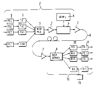
A further improvement in the process is shown in Figure 1.
5 Figure 1 illustrates a complete transmission system for
optical signals. A transmitter 1 is connected to a
transmission link 8. The transmission link 8 terminates at
a receiver 12. The transmitter 1 shown here has additional
components compared to the transmitter described with
loreference to Figure 3. The electric input signal is
firstly applied to a FEC unit 6. The electric input signal
passes from the output of the FEC unit 6 to the input of
the electro-optical transducer 2. The output of the
electro-optical transducer 2 is connected to the input end
l5of the wavelength division multiplexer 3. In this
exemplary embodiment the output of the wavelength division
multiplexer is connected to an amplifier 7. This in turn
is connected to the polarization modulator 4 and to a
further amplifier 7. The polarization modulator 4 is
2oconnected to a generator 5 for the modulation frequency.
The signal of the amplifier 7 passes across the
transmission link 8. The signal is applied to the input of
a receiver 12. In this case an amplifier 7 again forms the
first input stage. The output of the amplifier 7 is
25connected to a wavelength division demultiplexer 9 whose
outputs are each connected to an input of an opto-electric
transducer 10. The outputs of the opto-electric
transducers 10 are connected to FEC regenerators 11. For
the transmission of the optical signals in such a
3otransmission system, the polarization of the optical
signal, for example a 10 Gbit/s signal, is modulated with a
high frequency. The modulation frequency amounts for
example to 40 MFiz. A transmission system with polarization
mode dispersion can prove particularly susceptible to
35disturbances under certain conditions. For example, a
situation can occur in which the differential group delay
CA 02332204 2001-O1-24
6
time amounts to precisely one bit period and the power in
the two orthogonally polarized modes is equal. In such
cases even the use of a FEC process cannot ensure good
results in the recovery of the signal. Due to the
5modulation of the polarization, the system is "modulated"
out of such a state. The polarization of the optical
signal is modulated with a high frequency. This frequency
should be of sufficient magnitude to enable the bit errors
to be corrected with a FEC process. As a result of the
lomodulation with the high frequency and the averaging of the
polarization mode dispersion, bit error rates occur in a
short time scale. The resultant bit error rate can then be
further reduced by a FEC process. The averaging effect
improves the performance of the transmission system
l5compared to an unmodulated system.
Another embodiment uses a PMD equalizer in the receiver 12.
This filter is implemented as an electronic filter 13 as
described for example in German Application 199 36 254.8.
2oThe electronic equalizer 13 has been shown by way of
example outside the opto-electric transducer 10. In
another embodiment the equalizer is integrated in the opto-
electric transducer itself. When an electronic PMD filter
is used, it should be ensured that the reaction time of the
25filter is sufficiently fast to follow the modulation of the
polarization.
In another embodiment an optical PMD filter is used in the
receiver 12 prior to the opto-electric conversion. Another
embodiment employs an optical PMD filter in the receiver 12
3obefore the conversion of the optical signal and an
electronic PMD equalizer following the conversion.
Figure 4 illustrates another improved exemplary embodiment
of the WDM transmission system. In this embodiment an
35error-and-erasure algorithm is used. This known algorithm
Combined with a high-speed filter 13 enables the length of
CA 02332204 2001-O1-24
7
an error burst to be doubled and improves the PMD tolerance
of the optical receiver. An embodiment of the transversal
equalizer according to DE 199 936 254.8 is used for example
as filter 13. This filter supplies information about the
5use of the error-and-erasure method derived from the
control parameters of the filter 13. The filter must
supply information about the location of the error in the
signal to support the following stage of the error-and-
erasure processing of the signal.
The individual components must be adapted for the design of
a transmission system. The form described with reference
to Figure 1 and Figure 4 represents an exemplary embodiment
wherein no specific combination of components need be
l5provided for the application of the principle of the
invention.