Sélection de la langue

Search

Sommaire du brevet 2332667 

Énoncé de désistement de responsabilité concernant l'information provenant de tiers

Une partie des informations de ce site Web a été fournie par des sources externes. Le gouvernement du Canada n'assume aucune responsabilité concernant la précision, l'actualité ou la fiabilité des informations fournies par les sources externes. Les utilisateurs qui désirent employer cette information devraient consulter directement la source des informations. Le contenu fourni par les sources externes n'est pas assujetti aux exigences sur les langues officielles, la protection des renseignements personnels et l'accessibilité.

Disponibilité de l'Abrégé et des Revendications

L'apparition de différences dans le texte et l'image des Revendications et de l'Abrégé dépend du moment auquel le document est publié. Les textes des Revendications et de l'Abrégé sont affichés :

  • lorsque la demande peut être examinée par le public;
  • lorsque le brevet est émis (délivrance).
(12) Demande de brevet: (11) CA 2332667
(54) Titre français: CRIBLE ET PROCESSUS DE FABRICATION D'UNE TEL CRIBLE
(54) Titre anglais: SCREEN AND PROCESS FOR MANUFACTURING A SCREEN OF THIS KIND
Statut: Réputée abandonnée et au-delà du délai pour le rétablissement - en attente de la réponse à l’avis de communication rejetée
Données bibliographiques
(51) Classification internationale des brevets (CIB):
  • B07B 1/46 (2006.01)
  • B01D 29/11 (2006.01)
  • B01D 33/073 (2006.01)
  • B07B 1/20 (2006.01)
  • B07B 1/24 (2006.01)
  • B23P 15/12 (2006.01)
  • D21D 5/16 (2006.01)
(72) Inventeurs :
  • GABL, HELMUTH (Autriche)
  • PICHLER, AXEL (Autriche)
(73) Titulaires :
  • ANDRITZ AG
(71) Demandeurs :
  • ANDRITZ AG (Autriche)
(74) Agent: MARKS & CLERK
(74) Co-agent:
(45) Délivré:
(22) Date de dépôt: 2001-01-29
(41) Mise à la disponibilité du public: 2001-08-03
Licence disponible: S.O.
Cédé au domaine public: S.O.
(25) Langue des documents déposés: Anglais

Traité de coopération en matière de brevets (PCT): Non

(30) Données de priorité de la demande:
Numéro de la demande Pays / territoire Date
A 165/2000 (Autriche) 2000-02-03

Abrégés

Abrégé anglais


The invention refers to a flat or cylindrical screen, comprising rods and
rod-bearing supporting elements. It is mainly characterised by the rods 1
having indentations 3 in the side walls which gear into inversely shaped
recesses 4 in a supporting element 2. The invention also refers to a
process for manufacturing a screen of this kind, characterised by the
supporting elements 2 being bent open elastically and the rods 1 inserted,
whereupon the supporting elements 2 spring back, encircle the rods 1
positively and form a screen mat.

Revendications

Note : Les revendications sont présentées dans la langue officielle dans laquelle elles ont été soumises.


Claims
1. Flat or cylindrical screen, comprising rods and rod-bearing supporting
elements, characterised by the rods (1) having indentations (3) in the
side walls which gear into inversely shaped recesses (4) in a
supporting element (2).
2. Screen according to Claim 1, characterised by the indentations (3)
being circular or elliptical and preferably having a radius r of
0.1 mm < r < 2mm.
3. Screen according to one of Claims 1 or 2, characterised by the
spacing h1 between the indentations (3) and the end of rod (1)
facing away from the flow preferably measuring at least
0.1 mm < h1 < 6 mm.
4. Screen according to one of Claims 1 to 3, characterised by three or
more indentations (3) with the respective recesses (4) being provided
on one side wall.
5. Screen according to one of Claims 1 to 4, characterised by a
different number of indentations (3) being provided on either side of
the rods (1).
6. Screen according to one of Claims 1 to 5, characterised by the
supporting elements (2) having a T or I shape.
7. Screen according to one of Claims 1 to 6, characterised by the rods
(1), which have a total height H, protruding into the supporting
element (2) to a height h, where the relationship of h to H is preferably
greater than 0.5.
7

8. Screen according to one of Claims 1 to 7, characterised by the
bottom part of the rod being pressed together with the supporting
element (2).
9. Process for manufacture of a screen according to one of Claims 1 to
8, characterised by the supporting elements (2) being bent open
elastically and the rods (1) inserted, whereupon the supporting
elements (2) spring back, encircle the rods (1) positively and form a
screen mat.
10. Process according to Claim 9, characterised by the screen mat
being rolled together to form a cylinder.
8

Description

Note : Les descriptions sont présentées dans la langue officielle dans laquelle elles ont été soumises.

CA 02332667 2001-O1-29
Screen and process for manufacturing a screen of this kind
The invention relates to a flat or cylindrical screen, comprising rods and
rod-bearing supporting elements. In addition, the invention refers to a
process for manufacturing a screen of this kind.
Various types of screen are known, for example from WO 98/14658.
s Here, a screen is described which comprises a number of rods and
supporting elements, where the supporting elements have slots. In this
case the supporting elements take the shape of a U-profile, which means
that part of these rods must undergo plastic deformation in order to secure
the rods to the supporting elements. A different kind of screen is known
from DE 44 35 538 A1. Here, too, rods and rod-bearing supporting
elements are used, where the rods are secured with positive locking by
clamping due to plastic deformation of the rod-supporting elements. In
addition flat or cylindrical (centripedal or centrifugal) screens are known,
where the rods are attached by welding to the rod-supporting elements.
~5 This form of fastening, however leads to a series of disadvantages
because considerable welding stress is transferred to the components
during welding and this causes distortion of the entire screen body.
Furthermore, the fastening effect is not always guaranteed because the
welds may begin to break up under certain circumstances and in the
2o course of time due to signs of wear. The manufacturing process itself is
actually very complicated and time-consuming, and it is very difficult in
particular to set the supporting width precisely between two adjacent
screen rods.
2s The aim of the invention is thus to create a screen that does without
plastic deformation of the rods and/or supporting elements and without
2404
1

CA 02332667 2001-O1-29
welds. In addition, a simple manufacturing process for this type of screen
is to be developed.
The invention is thus characterised by the rods having indentations in the
side walls which gear into inversely shaped recesses in the supporting
element. Thus, a fixed connection can be created with form closure
without the need for welding or plastic deformation.
An advantageous further development of the invention is characterised by
the indentations being circular or elliptical and preferably having a radius r
of 0.1 mm < r < 2 mm. As a result, it is possible to mount the rods easily
without deformation of the supporting elements, which also permits
manufacture at low cost. The rods can be inserted easily, whereby the
circular or elliptical formed indentations lead to a more even area pressure
~5 and therefore to a good fixed connection with the supporting elements.
An advantageous configuration of the invention is characterised by the
spacing h~ between the indentations and the end of the rod facing away
from the flow preferably measuring at least 0.1 mm < h~ < 6 mm. This
2o makes the rod more resistant to vibration.
A favourable configuration of the invention is characterised by three or
more indentations with the respective recesses being provided on one
side wall. This means that a secure form closure can be achieved.
2404
2

CA 02332667 2001-O1-29
A favourable further development of the invention is characterised by a
different number of indentations being provided on either side of the rods.
This guarantees a better fastening effect in the event of one-sided onflow.
An advantageous further development of the invention is characterised by
the supporting elements having a T or I shape. This shape provides a
larger screen area.
A favourable configuration of the invention is characterised by the rods,
which have a total height H, protruding into the supporting element to a
height h, where the relationship of h to H is preferably greater than 0.5.
This protects the rod more effectively against flow forces.
An advantageous configuration of the invention is characterised by the
~5 bottom part of the rod being pressed together with the supporting element.
This provides even better stability at higher forces.
The invention also refers to a process for manufacturing a screen of this
kind, characterised by the supporting elements being bent open elastically
2o and the rods inserted, whereupon the supporting elements spring back,
encircle the rods positively and form a screen mat. Thus, a screen mat
can be formed easily without welding or pressing, where it is possible to
position the rods exactly and thus, obtain low tolerances.
25 An advantageous further development of the invention is characterised by
the screen mat being rolled together to form a cylinder.
2404
3

CA 02332667 2001-O1-29
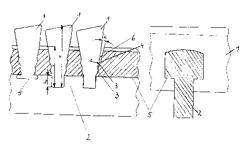
The invention is described below in examples and with reference to the
drawings, where Fig. 1 shows a variant of the invention and Fig. 2 shows a
section through the line marked II-II.
Figure 1 illustrates an example of three rods 1, mounted in supporting
elements 2. The right-hand rod 1 shows that it has several indentations 3
with a radius r on both side walls. The supporting element contains
recesses 4 with exact inverse shaping and the necessary clearance
distances in relation to the screen basket diameter. The present
illustration shows two indentations and two recesses on each side,
however there can also be three or more such indentations and recesses
if necessary. The number of indentations on either side may also differ.
These indentations with a circular or elliptical segment shape have a
radius r to which 0.1 mm < r < 2 mm applies. The rods can be inserted
~s easily, whereby the circular or elliptical formed indentations lead to a
more
even area pressure and therefore to a good fixed connection with the
supporting elements.
The middle rod in Figure 1 shows the length measurements of the rod,
which has an overall height H. The indentations are spaced at a distance
2o h~ to which 0.1 mm < h~ < 6 mm applies, from the end of the rod facing
away from the flow. The rod 1 projects into the supporting element with a
height h, where the relationship of h to H should preferably be larger than
0.5. The projecting section of the rod on the side facing away from the
flow can be pressed together with the surfaces 5 of the supporting
2s element to obtain better fastening. This applies if the supporting element
2 is made in a T shape. If an I shape is used, the rod 1 is not pressed
together. The supporting element 2 can also be made in other shapes
than a T or I, e.g. square, rectangular, square with rounded corners,
rectangular with rounded corners, with the rounding on only one or on
2404
4

CA 02332667 2001-O1-29
several corners. The indentations provided in the supporting element 2 to
hold the rod 1 can have clearance equivalent to the angle ~ on the side
facing away from the flow. With the cylindrical shape of the screen basket
this avoids plastic deformation in the supporting element 2.
Figure 2 shows a section through the line marked II-II in Fig. 1, where the
T shape of the supporting element 2 and one rod 1 are visible. On the
surface 5 this rod 1 can be pressed together with the supporting element 2
if necessary.
The connection between rods and supporting elements is essentially
positive, i.e. without plastic deformation of the individual components or
additional connecting links, such as weld seams. A screen of this type
can be made, for example, by pressing the rods together with the
supporting elements until they lock into place. Another form of
manufacture is to bend the supporting elements open elastically so that
the recesses 6 for the rods expand and the individual rods 1 can be
inserted. When the supporting elements have sprung back into place, a
level screen mat is formed by the clamped profile rods. Thanks to the
2o above mentioned design as snap connection, this process permits the
rods 1 to be inserted precisely into the supporting elements 2, thus
lowering the slot width tolerances. If this level screen is then shaped into
a screen basket, the clamping effect is increased further due to the
bending radius when the screen is rolled up. Pressing the protruding ends
of the rods together with the supporting elements 2 increases the stability
of the screen mat further. The supporting elements 2 can also be shaped
as rings with the indentations 6 according to the invention worked into
these rings, where the dimensions are somewhat smaller than specified,
i.e. the indentations 6 are slightly smaller than the rods 1. Subsequently
2404
5

CA 02332667 2001-O1-29
the rings are nicked at one point and bent open far enough for the rods to
lock into place. When the rings have bent back into place, they can be
welded together to form a basket.
The invention is not limited to the examples presented. On the contrary,
the indentations 3 in the rods 1 can be shaped at will as long as they
engage in the inversely identical recesses in the supporting element. The
rods 1 can also take any shape from a rectangle to a triangle.
2404
6

Dessin représentatif
Une figure unique qui représente un dessin illustrant l'invention.
États administratifs

2024-08-01 : Dans le cadre de la transition vers les Brevets de nouvelle génération (BNG), la base de données sur les brevets canadiens (BDBC) contient désormais un Historique d'événement plus détaillé, qui reproduit le Journal des événements de notre nouvelle solution interne.

Veuillez noter que les événements débutant par « Inactive : » se réfèrent à des événements qui ne sont plus utilisés dans notre nouvelle solution interne.

Pour une meilleure compréhension de l'état de la demande ou brevet qui figure sur cette page, la rubrique Mise en garde , et les descriptions de Brevet , Historique d'événement , Taxes périodiques et Historique des paiements devraient être consultées.

Historique d'événement

Description Date
Demande non rétablie avant l'échéance 2007-01-29
Le délai pour l'annulation est expiré 2007-01-29
Inactive : CIB de MCD 2006-03-12
Réputée abandonnée - omission de répondre à un avis sur les taxes pour le maintien en état 2006-01-30
Inactive : Abandon.-RE+surtaxe impayées-Corr envoyée 2006-01-30
Demande publiée (accessible au public) 2001-08-03
Inactive : Page couverture publiée 2001-08-02
Inactive : CIB en 1re position 2001-03-30
Inactive : CIB attribuée 2001-03-30
Inactive : Certificat de dépôt - Sans RE (Anglais) 2001-02-27
Exigences de dépôt - jugé conforme 2001-02-27
Lettre envoyée 2001-02-27
Demande reçue - nationale ordinaire 2001-02-26

Historique d'abandonnement

Date d'abandonnement Raison Date de rétablissement
2006-01-30

Taxes périodiques

Le dernier paiement a été reçu le 2004-12-02

Avis : Si le paiement en totalité n'a pas été reçu au plus tard à la date indiquée, une taxe supplémentaire peut être imposée, soit une des taxes suivantes :

  • taxe de rétablissement ;
  • taxe pour paiement en souffrance ; ou
  • taxe additionnelle pour le renversement d'une péremption réputée.

Veuillez vous référer à la page web des taxes sur les brevets de l'OPIC pour voir tous les montants actuels des taxes.

Historique des taxes

Type de taxes Anniversaire Échéance Date payée
Taxe pour le dépôt - générale 2001-01-29
Enregistrement d'un document 2001-01-29
TM (demande, 2e anniv.) - générale 02 2003-01-29 2003-01-21
TM (demande, 3e anniv.) - générale 03 2004-01-29 2003-12-23
TM (demande, 4e anniv.) - générale 04 2005-01-31 2004-12-02
Titulaires au dossier

Les titulaires actuels et antérieures au dossier sont affichés en ordre alphabétique.

Titulaires actuels au dossier
ANDRITZ AG
Titulaires antérieures au dossier
AXEL PICHLER
HELMUTH GABL
Les propriétaires antérieurs qui ne figurent pas dans la liste des « Propriétaires au dossier » apparaîtront dans d'autres documents au dossier.
Documents

Pour visionner les fichiers sélectionnés, entrer le code reCAPTCHA :


Pour visualiser une image, cliquer sur un lien dans la colonne description du document. Pour télécharger l'image (les images), cliquer l'une ou plusieurs cases à cocher dans la première colonne et ensuite cliquer sur le bouton "Télécharger sélection en format PDF (archive Zip)" ou le bouton "Télécharger sélection (en un fichier PDF fusionné)".

Liste des documents de brevet publiés et non publiés sur la BDBC .

Si vous avez des difficultés à accéder au contenu, veuillez communiquer avec le Centre de services à la clientèle au 1-866-997-1936, ou envoyer un courriel au Centre de service à la clientèle de l'OPIC.


Description du
Document 
Date
(aaaa-mm-jj) 
Nombre de pages   Taille de l'image (Ko) 
Dessin représentatif 2001-08-02 1 13
Abrégé 2001-01-29 1 14
Description 2001-01-29 6 212
Revendications 2001-01-29 2 44
Dessins 2001-01-29 1 24
Page couverture 2001-08-02 1 39
Courtoisie - Certificat d'enregistrement (document(s) connexe(s)) 2001-02-27 1 113
Certificat de dépôt (anglais) 2001-02-27 1 162
Rappel de taxe de maintien due 2002-10-01 1 109
Rappel - requête d'examen 2005-10-03 1 116
Courtoisie - Lettre d'abandon (requête d'examen) 2006-04-10 1 166
Courtoisie - Lettre d'abandon (taxe de maintien en état) 2006-03-27 1 177