Note : Les descriptions sont présentées dans la langue officielle dans laquelle elles ont été soumises.
FIELD OF INVENT10N
The present invention relates to methods of constructing packed-bed and
monolith reactorslconverters with improved stability against process
disturbances and of controlling transient reactor behavior.
BACKGROUND OF THE INVENTION
Many commercial catalytic reactions are exothermic, hence they are
inherently prone to self-acceleration and thermal runaway. Furthermore, the
catalyst bed absorbs a fraction of reaction heat and thereby slows down the
transport of heat relative to that of matter. This unbalanced transport of
heat and
matter, in combination with positive temperature feedback gives rise to
reactor
dynamic instability. As a result, in response to accidental changes of
operating
parameters (feed temperature, composition, and flow rate, etc.) or during
planned transient operations (start-up, shut-down, load change) these reactors
tend to develop transient waves of temperature and chemical composition
(Onken H.U. and Wicke E., 1986, Statistical Fluctuations of Temperature and
Conversion at the Catalytic CO Oxidation in an Adiabatic Packed Bed
Reactor, Ber. Bunsen. Ges. Phys. Chem., 90, 976; and Chen Y. C. and Luss D.,
1989, Wrong-Way Behavior of Packed Bed Reactor: Influence of Interphase
Transport, AIChE J., 35,1148). The peak temperatures of these waves can
substantially exceed the maximum temperature of steady-state reactor
operation. Such transient traveling hot spots (THSs) represent hazards to the
safe and efficient reactor operation: they can limit throughput, selectivity
and
product quality, and shorten the life of catalyst and of other reactor
components.
Packed-bed reactors, especially those with big adiabatic beds, can be
sensitive even to small procEas disturbances, operating under certain
conditions
as resonant amplifiers of incoming perturbations. On the other hand, very
large
variations of operating pararneters are inherent in the operation of monolith
converters and combustors in automotive and power generation industries.
1
.:::::....:.:::::....:...::::...:.:...:....:::::::::....:: :::.:.:_:. ~ ~..r.
".r a ~ -.
:.::: ~:::'::::::::~s::a:::::.:::.::::;:::~f:::~:: Q . .
t~ .. _;~.,
,.:;,.,....,.,...,,~;,CA 02333549 2000 11 27 :...
1~~1~ : w _ _ '...':
WO 99/64145 PCT/CA99/00523
Despite the better dynamic (transient) stability of monolith reactors,
relative to
packed beds, car catalytic converters develop sharp, highly localized
temperature spikes, triggered by severe variations of inlet conditions during
acceleration-deceleration cycles, {Kirchner T. and Eigenberger G., 1997, On
the
Dynamic Behavior of Automotive Catalysts, Catalysis Today, 38, 3) and other
transient maneuvers (Oh Se H. and Cavendish J.C., 1982, Transients of
Monolithic Catalytic Converters: Response to Step Changes in Feedstream
Temperature as Related to Controlling Automobile Emissions, Ind. Eng.
Chem. Prod. Res. Dev., 21, 29). Another air pollution control device that can
be
viewed as a monolithic exothermal reactor is the diesel-particulate trap. Its
most
popular type, namely the wall-flow filter, represents a ceramic monolith with
axial
channels open at one end <~nd closed at another. The open and closed channels
alternate in a checkerboard manner, hence, exhaust gas is forced through the
porous channel walls before it can escape from the trap. This constitutes a
filtration process. When the soot load reaches a certain level, the trap must
be
cleaned up (regenerated}, generally by combustion (thermal or catalyticaily
assisted) of soot inside the filter.
Common problems with the monolith reactors and diesel-particulate traps
arise from their overheating and from the sharp temperature gradients and
thermal stresses that develop during transient operation. Thermal ageing of
the
automobile catalytic converters results mainly from high-temperature sintering
of
catalyst and support and from deactivating catalyst-carrier interactions (Heck
R.M. and Farrauto R.J., 1995, Catalytic Air Pollution Control: Commercial
Technology, Van Norstrand Reinhold, New York). In the diesel-particulate
traps, during the regeneration process that has the character of a self-
propagating combustion wave, the heat released sometimes causes the monolith
to crack or to melt {Neeft J.P.A., Makee M., Moulijn J.A., 1996, Diesel
Particulate Emission Control, Fuel Processing Technology 47, 1 ). Serious
overheating problems also occur in emerging catalytic technologies, e.g.
2
CA 02333549 2000-11-27
WO 99/64145 PCT/CA99/00523
catalytic NOX reduction in lean environments and catalyticaily supported
thermal
combustion (Heck R.M. and Farrauto R.J., 1995, Catalytic Air Pollution
Control: Commercial Technology, Van Norstrand Reinhold, New York). In the
catalytic combustion of fuels for power generation on monolith combustors, one
;i encounters demanding thermal regimes, unmatched in any other catalytic
technology. During planned transient operation (start-up, shut-down, load-
change) or as a result of accidental process disturbances, the catalyst and
substrate may experience temperatures as high as 1300-1400°C, sometimes
with catastrophic consequences (Heck R.M. and Farrauto R.J., 1995, Catalytic
Air Pollution Control: Commercial Technology, Van Norstrand Reinhold, New
York; and Kolaczkowski S. T., 1996, Catalytic Stationary Gas Turbine
Combustors: A Review of the Challenges Faced to Clear the Next Set of
Hurdles, Trans. I. Chem. E. 73a, 168).
There are currently several methods of preventing noxious temperature
1;5 waves, traveling hot spots, iin commercial catalytic reactors. These
include
thorough control of operating parameters (inlet temperature, flow rate,
composition of feed). This is the standard approach in chemical plants where
stable operation is achieved by feedback control systems. In power generation,
however, and (especially) in automotive exhaust clean-up, the very nature of
the
applications involves large variations of inlet conditions. This severe
external
forcing produces a nonlinear, saturated response, and sometimes leads to
dramatic noxious temperature wave overshoots that are damaging to catalyst
and substrate (Kirchner T. and Eigenberger G., 1997, On the Dynamic
Behavior of Automotive Catalysts, Catalysis Today, 38, 3; and Oh Se H. and
2.5 Cavendish J.C., 1982, Transients of Monolithic Catalytic Converters:
Response to Step Changes in Feedstream Temperature as Related to
Controlling Automobile Emissions, Ind. Eng. Chem. Prod. Res. Dev.,21,29).
Another method of preventing noxious traveling hot spots in commercial
catalytic reactors is conservative operation under mild operating conditions
3
CA 02333549 2000-11-27
WO 99/64145 PCT/CA99/00523
(dilute feeds and catalysts, low space velocities). However, the price paid
for this
safety is a reduced throughput.
Appropriate reactor design and choice of parameters is another approach
taken to alleviate the problem of traveling hot spots. An important paradigm
of
this approach, that is not widely recognized, is utilization of the catalyst-
pellet
size as a parameter governing reactor stability (Matros Yu. Sh., 1985,
Unsteady
Processes in Catalytic Reactors, Elsevier Science, Amsterdam}. The use of
large pellets (up to l0mm in diameter) entails a decreased observed activation
energy of the reaction and an increased fluid-solid heat flow resistance. The
former diminishes the tendency of the reaction to self-accelerate, improving
thereby both dynamic and static reactor stability. The latter exerts on the
reactor
an influence similar to that of heat dispersion which tends to even out
temperature inhomogeneities, suppressing the tendency of the reactor to form
noxious temperature waves. In monolith reactors, the thermal properties of the
monolith material, the channel size and wall thickness have a profound
influence
on temperature wave formation.
There is a need for packed-bed reactors, monolith reactors and diesel-
particulate traps with enhanced operational stability, less prone to
overheating
and thermal deterioration during transient operation. Such reactors could be
operated at higher levels of throughput without compromising their operational
safety and quality of the process (e.g. selectivity and product quality in
production applications}. A further advantage that derives from improved
reactor
stability is a greater durability of the equipment including longer life of
catalyst
and other reactor components.
t'.5
SUMMARY OF THE INVENTION
The present invention provides a method of adaptive control of
temperature fluctuations arising from transient heat waves in exothermal
catalytic reactors, comprising:
4
CA 02333549 2000-11-27
_. ._ .___ __ __ ._-_ _ -_. _... .a. - ~. _ ~ rmV~_W Jv~o~ r!t:~ YW
%:K:.i~i~.u.ns:v:r ,
2t~-~o-2~7~V C~, OO~~O~SGJ
providing at least twc~ component exotherrnal catalytic reactors, each of
said at least two component exotherma! catalytic reactors including means far
inducing identical process disturbances to propagate in said at least two
component catalytic reactors at different speeds and evolve into differanl,
phase-shifted t~mperature ruaves; and
thermally coupling said at least two component exothermal catalytic
reactors so that heat exchange occurs between said at least two component
exothertnal catalytic reactors in the radial direction, wherein said phase-
shifted
temperature waves in each of said at least t~wa component exothem~al catalytic
reactors destructively interfere through radial inter-reactor heat fiiuw
then.by
dampening said temperature fluctuations and reducing deviations of reactor
temperature fields from desirable steady state temperature profiles.
In another aspect of the invention there is provided an exotherrnal
catalytic reactor with adaptive control of temperature fluctuations,
comprising:
't5 at least two component exothermal catalytic reactors each having a
longitudinal direction, said at least two component exothermal catalytic
reactors
being thermally coupled so that heat exchange occurs between said at least two
component exothermal catalytic reactors in the radial direction;
each of said at least two component exothermal catalytic reactors
including means for inducing identical process disturbances to propagate in
said at least two component catalytic reactors at different speeds and evolve
into
different, phase-shifted temperature waves, wherein said phase-shifted
temperature waves in each of said at least two component exothermdt catalytic
reactors destructively interfere through radial inter reactor heat flow
thereby
dampening said temperature fluctuations and reducing deviations of reactor
temperature fields from desirable steady state temperature profiles.
In an embodiment of the reactor using passive inserts to obtain
stabilization, if the reactor and passive insert are not thermally coupled
there will
b2 wave in the reactor and na wave in the passive insert. lNhen the reactor
and
the insert are thermally coupled, the wave in the reactor induces secondary
wave in the insert and drags this secondary wave downstream. The secondary
wave lags behind being thus phase-shifted (phase-delayed relative to the
CA 02333549 2000-11-27 AMENDED SHEET
WO 99/64145 PCT/CA99/00523
primary wave in the reactor. The very same radial heat flow that gives rise to
the
secondary wave makes the primary and the secondary waves destructively
interfere.
BRIEF DESCRIPTION OF THE DRAWINGS
The method of enhancing stability and performance of catalytic
exothermal reactors in accordance with the present invention will now be
described, by way of example only, reference being had to the accompanying
drawings, in which;
Figure1 a is a schematic diagram of various types of a prior art catalytic
reactors such as basic packed-bed reactor (PBR), or monolith reactor (MR);
Figure1 b is a schematic diagram of various types of co-current PBR or
MR of the present invention, composed of two dynamically different component
reactors;
Figure 1c is a schematic representation of a prior art counter-current
tandem PBR or MR, composed of two identical component reactors;
Figure 1d is a schematic representation of a bent reactor with internal
counter-current heat exchange;
Figure 1 a is a schematic representation of a tandem reactor of the
present invention with catalyst removed from non-functional downstream parts
of
component reactors;
Figure 1 f is a schematic representation of a prior art bent reactor with one
sleeve emptied of catalyst, since only one sleeve can be used to carry the
reaction;
Figure 2a is a cross-sectional view of a stabilized reactor with a shell and
tube configuration constructed in accordance with the present invention;
Figure 2b is a cross sectional view of a stabilized packed-bed reactor of
the present invention constructed with a checkerboard configuration;
Figure 2c is a cross sectional view of a checkerboard configuration for a
6
CA 02333549 2000-11-27
WO 99/64145 PCT/CA99/00523
monolith reactor constructed in accordance with the present invention;
Figure 3a is a cross sectional view of a stabilized packed-bed reactor
constructed in accordance with the present invention using a passive-insert
stabilization scheme with the passive-inserts being rods (depicted by black
circles);
Figure 3b is a cross sectional view of a stabilized packed-bed reactor
constructed in accordance 'with the present invention using a passive-insert
stabilization scheme with the passive-inserts being internal walls, running
along
the reactor axis;
Figure 3c is a cross sectional view of a stabilized monolith reactor
constructed in accordance with the present invention using a passive-insert
stabilization scheme with the passive-inserts being in the form of massive
internal walls;
Figures 4a and 4b show plots of temperature response of two packed-bed
reactors with different Lewis numbers to slight periodic variations of the
temperature of feed for the two packed-bed reactors operating independently;
Figures 4c and 4d show plots of temperature response of two packed-bed
reactors with different Lewis numbers to slight periodic variations of the
temperature of feed for the two packed-bed reactors being co-currently
thermally
coupled as shown in Figure 1 b;
Figure 5a shows a reference response of an isolated packed-bed reactor
of Figure 1a. A snapshot of transient temperature distribution is shown (wavy
curve) as welt as temperature envelopes and uncertainty.
Figure 5b shows similar data to Figure 5a but for the case when the
reactor operates as a component of the counter-current arrangement of
Figure1 c;
Figure 6a shows a reference temperature response of a basic packed-bed
reactor of Figure 1a to a small-amplitude periodic perturbation of the
temperature of feed (dotted curve) and response of a reactor stabilized by
7
CA 02333549 2000-11-27
WO 99/64145 PCT/CA99/00523
passive inserts in the form of internal walls of Figure 3b (solid curve);
Figure 6b shows the temperature response of stabilized catalyst bed
(solid line) of Figure 3b and of a passive insert, an internal wall, used to
stabilize the bed (broken line);
;i Figure 6c is a plot showing temperature envelopes for the basic packed-
bed reactor (dotted-line being the reference response) and for the passive-
insert
stabilized packed-bed reactor (solid line);
Figure 7a illustrates the improved dynamic stability of a checkerboard
monolith reactor of Figure 2c (solid lines) relative to the basic monolithic
reactor
1() of Figure 1a (broken lines); and
Figure 7b demonstrates stabilization of monolith reactor operation using
passive inserts stabilization scheme of Figure 3c under typical conditions of
the
MR production applications.
1 Ei DETAILED DESCRIPTION OF THE INVENTION
Prior art catalytic reactors of the type schematically illustrated in Figure1a
are widely used in chemical and petrochemical industries as well as in
automotive (car catalytic converter) and environmental (VOC incinerator)
applications. A new, emerging technology, namely catalytic combustion for
2U power generation in gas turbines, involves catalytic monolith combustor as
its
core unit. Catalytic reactors comprise a porous soiid support and, bound to
it, a
catalytically active component which promotes the reaction of interest. In
packed-bed reactors (PBRs) the support is granular, and in monolith reactors
(MRs) it represents a rigid ceramic or metallic structure with a multitude of
2;i regular, axial channels.
The present invention discloses methods of rendering exothermal
reactors, such as but not limited to packed-bed reactors, monolith reactors
and
diesel-particulate traps, inherently more stable, compared to their
conventional
counterparts, in the sense that their tendency to develop transient waves of
8
CA 02333549 2000-11-27
WO 99/64145 PCT/CA99/00523
temperature and chemical composition is considerably diminished. The invention
exploits the stabilizing effect of lateral heat exchange between different
radial
sections of the reactor in which the heat waves are made to develop phase
shifts
relative to each other. These phase-shifted waves attenuate each other through
radial heat flows, which process can be likened to destructive interference.
Another source of enhanced reactor stability is the increased thermal
conductance of the bed which is operative when passive inserts are employed
as a means of reactor stabilization. Both contributing factors, destructive
interference of heat waves and enhanced heat conductance of the bed, promote
1~~ more uniform distribution of heat carried by temperature waves over
reactor
volume diminishing both the maximal transient temperatures and the
temperature gradients. The area of applicability of thus stabilized reactors
(SRs)
includes chemical and petro-chemical industries as well as automotive (car
catalytic converter), environmental (VOC incinerator) and power/heat
generation
1.5 (catalytic combustor) applications.
The present invention achieves the objective of controlling transient
behavior of exothermal reactors by employing reactor designs that have an
improved dynamic stability built into their structure. This signifies enhanced
resilience of the stabilized reactors against process disturbances and
smoother
2'D operation during planned transient maneuvers, compared to their
conventional
counterparts. Reduced deviations of intra-reactor temperature fields from
their
intended stationary profiles are achieved through a more uniform distribution
of
heat carried by transient temperature waves over the reactor volume. The
invention provides reactor designs that exploit destructive interference of
25 transient heat waves and enhanced thermal conductance of the bed. This is
achieved through the following two approaches.
The first approach, the coupled-reactor (CR) scheme, involves thermally
coupled operation of two or more component reactors. When operated in the co-
current mode as shown in Figure1 b, the component reactors must be
CA 02333549 2000-11-27
WO 99/64145 PCT/CA99/00523
dynamically different in the sense that identical process disturbances evolve
in
them into different, phase-shifted transient waves. This is accomplished
through
different thermal properties of the catalyst carriers (e.g. different heat
capacities)
in these reactors or different space velocities. Transient waves in reactor
with
faster flow or with lower heat capacity propagate at increased speeds. Due to
this difference in propagation speeds, transient waves in component reactors
accumulate a phase-shift and interfere destructively through radial inter-
reactor
heat flows. In the counter-current mode, shown in Figure1c, identical
component
reactors may be used since the transient waves propagate in opposite
directions.
Figures 2a, 2b and 2c; show different embodiments of operationally
stabilized reactors that implement the coupled-reactor stabilization scheme.
Figure 2a shows a stabilized reactor 20 including a shell 22 and tubes 24 on
the
interior of the shell to form a shell and tube configuration. In co-current
stabilized
1 ~~ reactors using this, 20, configuration, both the shell 22 and the tubes
24 are
filled with catalyst. The shell and tube sides are operationally (dynamically)
different e.g. through different heat capacities of catalyst carriers in them
as
described above. Catalytic component may be the same with different catalyst
carriers. In counter-current stabilized reactors 20, certain domains of the
reactor's inner space must be void of catalyst as shown in Figure 1 a because
of
the parametric sensitivity considerations discussed below (see EXAMPLE 2).
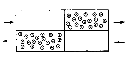
Figure 2b shows a packed-bed reactor 30 having a checkerboard configuration
including for the co-current stabilized reactor, internal walls 32 that sub-
divide
the inner volume of the reactor into prismatic sections 34 filled with
catalyst such
2C~ that adjacent cells are dynamically different e.g. through different heat
capacities
of catalyst carriers 36 and 38. Complete leak-tight separation of cells is not
necessary, so that a frame composed of internal partitions (e.g. metal sheets)
may be placed inside the shell loosely and then filled with catalyst in a
checkerboard manner. This scheme is not convenient for the counter-current
CA 02333549 2000-11-27
WO 99/64145 PCT/CA99/00523
stabilized reactors where complete separation of fluids flowing to meet each
other must be provided in order to sustain pressure gradients of opposite
signs
driving these flows. Figure 2c shows a cross section of a monolith reactor 40
having a checkerboard configuration to be used in chemical manufacturing
processes, car exhaust.clean-up, VOC incineration, catalytic combustion for
power and heat generation, diesel particulate matter retention and
incineration.
The reactor is composed of alternating domains 42 and 44 with different
thermal
(e.g. heat capacity), operational (e.g space velocity), geometrical (e.g,
channel
wall thickness) or other properties.
The second stabilization method, referred to as the passive-insert (PI)
method, employs embedding into the packed bed or monolith of extra heat
capacitylconductance in the form of axial internal walls, rods, plates, etc.
The
role of these passive-inserts is to absorb a fraction of the excess reaction
heat
released during an upward temperature excursion and to release it later on,
1 ~~ ideally during a downward deviation of the bed temperature. The passive-
inserts
also act as thermal shunts that reinforce the effective heat conductance of
the
bed and convey heat from the transient traveling hot spots to adjacent cooler
areas.
Figures 3a, 3b and 3c; show different embodiments of stabilized reactors
based on the passive-insert stabilization scheme. Figure 3a illustrates a
cross
section of a packed-bed reactor 60 with the passive-inserts 62 in the form of
axial rods (depicted by black circles) surrounded by catalyst particles 64.
Figure
3b illustrates a packed-bed reactor 70 including internal walls 72 running
along
the reactor axis among the catalyst particles 74. Figure 3c shows a cross
section
2~~ of a monolith reactor 80 with the passive inserts in the form of selected
reinforced channel walls 82 as compared to thinner regular channel walls 84.
In the embodiment of the method using coupled-reactor
stabilization, phase-shifted temperature waves develop due to the dynamical
difference of companent reactors. Even if there is no heat exchange between
the
11
CA 02333549 2000-11-27
WO 99/64145 PCT/CA99/00523
reactors, transient waves exist in the reactors whether or not they are
thermally
coupled and will in general be phase-shifted with respect to each other.
Radial
heat flows between the thermally coupled reactors results in these pre-
existing
phase-shifted waves destructively interfering.
:5 In the embodiment of the method using passive inserts, if reactor and
passive insert are not thermally coupled there will be wave in the reactor and
no
wave in the passive insert. lNhen the reactor and the insert are thermally
coupled, the wave in the reactor induces secondary wave in the insert and
drags
this secondary wave downstream. The secondary wave lags behind being thus
1 () phase-shifted (phase-delayed) relative to the primary wave in the
reactar. The
very same radial heat flow that gives rise to the secondary wave makes the
primary and the secondary waves destructively interfere.
The stabilized reactors that implement coupled-reactor- or passive-insert
stabilization schemes rely on efficient heat exchange among the reactor's
1;i adjacent radial zones. This its necessary for destructive interference of
the heat
waves to occur or for the passive inserts to contribute their capacity to
conduct
heat effectively. The pitch, D, of the radial structure of a stabilized
reactors,
namely the distance between the neighbouring Pls or between component
reactors, is determined by the distance of lateral drift of the heat within
the
2() reactor's thermal response lame. For the packed-bed reactors, D
approximately
equals (due"e,L)'~2, where dpe,~e, is the catalyst pellet size and L is the
reactor
length. Here L is representative of the reagent residence time inside the
reactor
(hence of the reactor thermal response time) and dPe"et represents the mean
free
path of the lateral turbulent heat dispersion inside the packed bed. E.g. for
2;i d~"e~ 5mm and L=2m, D=1C)cm.
Because of their greater stability, the stabilized reactors disclosed herein
can be operated more aggressively than their conventional counterparts to
attain
higher levels of productivity. Alternatively, they can be operated more safely
to
extend the life-span of the catalyst and to improve the quality of the
process, e.g.
12
CA 02333549 2000-11-27
WO 99/64145 PCT/CA99/00523
selectivity in production applications, that is generally a sensitive function
of
temperature.
The radial heat exchange among the component reactors may be
configured to occur through an additional (e.g. cooling) medium. As well, the
reactors may be configured so that destructive interference of transient waves
in
the component reactors occurs through delayed interaction of similar or
dissimilar component reactoirs through an additional (e.g. cooling) medium.
A reactor may also be: constructed in accordance with the present
invention wherein the maximum temperature of the stationary hot spot and
reactor parametric sensitivity are reduced through the interaction via cooling
medium among the component reactors, in which stationary hot spots are
positioned at different locations along the reactor axis. The difference in
locations of the stationary hot spots in component reactors is achieved for
example through the difference of flow velocities of reagents in said
component
reactors.
The following nonlimiting examples will further exemplify the method of
stabilizing reactors and constructing stabilized reactors for various
applications.
EXAMPLE 1
The coupled-reactor stabilization scheme is illustrated in Figure1 b for the
co-current stabilized reactor and involves thermally coupled operation of two
component reactors. The latter are designed to be dynamically different in the
sense that identical perturbations evolve in them differently, e.g. propagate
at
different speeds. The goal is to force the same process disturbances to
develop
in the component reactors into heat waves that are phase-shifted relative to
each other. With the reactor sizing and thermal properties appropriately
chosen,
radial heat exchange between the component reactors tends to suppress the
temperature waves in them through the mechanism similar to destructive
interference. This constitutes the adaptive mechanism of enhanced dynamic
13
CA 02333549 2000-11-27
WO 99/64145 PCT/CA99/00523
stability built into the stabilised reactor structure. As an example one may
use
two adiabatic packed-bed reactors with an exothermic reaction A=>B+heat, first
operating independently and subsequently in a co-current arrangement.
The propagation speed of the heat waves in a packed-bed reactor is
inversely proportional to its Lewis number Le = j(1-E)p,Cs + ep,C, ] /Ep,Cf (e
is
the void fraction of the bed; ~~5, p~ and CS, C, are the solid/fluid densities
and heat
capacities). The reference response of two packed-bed reactors with different
Lewis numbers to a periodic perturbation is shown in Figures 4a and 4b in
which
the reactors operate independently. The curves 1 show the snapshots of
transient temperature distributions inside the reactors: the waves that have
evolved from identical perturbation are phase-shifted relative to each other.
The
curves 2 show the upper and the lower temperature envelopes, the curves 3
(dotted) show the steady-state temperature profiles, and the curves 4 show the
difference of the upper and lower temperature envelopes (temperature
uncertainties). The perturbation is applied to the feedstream temperature, Ta,
and it has amplitude 0.01 To. Transients which originate from these slight
variations of the inlet temperature grow into the large-amplitude travelling
waves
of heat and chemical composition. The difference of upper and lower
temperature envelopes which confine these waves (the temperature uncertainty)
serves as a measure of reactor operational instability. Because of the
difference in the Lewis numbers of the component reactors, transient waves
propagate in them at different speeds and a phase-shift builds up between
them.
The response of the above reactors to the same perturbation after they
have been co-currently thermally coupled (Figure1 b) is shown in Figures 4c
and
4d. While the steady-state temperature profiles are unaffected, the transient
response is drastically reduced by the coupling. The improved stability of
coupled configuration is evident: the temperature excursions are now confined
to
the immediate vicinity of the steady states and the temperature uncertainties
are
reduced both in amplitude and in width.
14
CA 02333549 2000-11-27
WO 99/64145 PCT/CA99/00523
EXAMPLE 2
Another realization of the coupled-reactor approach is the counter-current
stabilized reactor shown in Figure1c. Dynamic dissimilarity of component
;i reactors necessary to produce a phase-shift between the heat waves in them
is
inherent in this configuration since these waves propagate in opposite
directions. This gives the reactor, composed of identical counter-currently
coupled component reactors, a high degree of stability, as illustrated by
Figure
5b (to be compared with the reference response of an isolated packed-bed
reactor shown in Figure 5a). A snapshot of transient temperature distribution
is
shown (wavy curve) as well as temperature envelopes and uncertainty.
Packed-bed reactors with integrated counter-current heat exchange are
employed in industry to achieve autothermal operation when hot reaction
products preheat cold feed so that no external heat supply is necessary (Aris
R.,
1989, Elementary Chemical Reactor Analysis, Butterworth, Boston; Froment
G. F. and Bischoff K. B., 1990, Chemical Reactor Analysis and Design, John
Wiley, New York; Eigenberger G. and Nieken U., 1994, Catalytic Cleaning of
Polluted Air: Reaction Engineering Problems and New Solutions,
Int.Chem.Eng., 34, 4) . A famous example of this reactor type is the TVA
reactor
for ammonia synthesis {see e.g. Aris R., 1989, Elementary Chemical Reactor
Analysis, Butterworth, Boston). The elementary (conceptual) unit of the
counter-
current autothermal reactors is a reactor obtained by coupling of two basic
PBRs
of Figure 1 a in a counter-current arrangement of Figure 1 c (see e.g. Sun Q.,
Young B., Williams D.F., Glasser D. and Hildebrandt D., 1995, A Periodic Flow
2;i Reversal Reactor: an Infinitely Fast Switching Model and a Practical
Proposal for its Implementation, Abstr. of the USPC-2 Conference, St. Louis,
Missouri, USA.) or from a single basic packed-bed reactors by bending it at
the
mid-point and bringing the resultant branches into thermal contact as shown in
CA 02333549 2000-11-27
WO 99/64145 PCT/CA99/00523
Figure 1d. These reactor models, however, become parametrically sensitive and
extinguish abruptly when the reaction zone approaches the mid-point of the
tandem counter-current reactor or the knee of the bent reactor. Hence, the
inlet
branch [Aris R., 1989, Elementary Chemical Reactor Analysis, Butterworth,
Boston] or the outlet branch (Eigenberger G. and Nieken U., 1994, Catalytic
Cleaning of Polluted Air: Reaction Engineering Problems and New
Solutions, Int.Chem.Eng., :14, 4) of the bent reactor or the up-(downstream
halves of the component reactors in the counter-current arrangement must be
emptied of catalyst. These reactor domains cannot be used because of the
1 C~ above limitation imposed on the reaction zone location. Moreover, if
packed,
they would produce extra hydraulic resistance of the bed. Two examples of this
family of reactors are shown. schematically Figures1e and 1f. If operating
conditions of two component reactors of the tandem configuration are
identical,
this reactor is operationally equivalent to the bent reactor with the
15 correspondence rules: c -> d, a -> f .
Stability of autothermal reactors is usually considered within the
framework of parametric sensitivity approach that is based on reactor response
to (infinitely) slow perturbations (Morbidelli M. and Varma A., 1982,
Parametric
Sensitivity and Runaway in Tubular Reactors, AIChE J., 25, 903). Dynamic
20~ aspect of the counter-current reactors stability is twofold. First, due to
destructive interference of heat waves in component reactors, resonant
disturbance amplification, characteristic of basic packed-bed reactors, is
virtually
eliminated. Secondly, thermal response time of this reactor is longer than
that of
single packed-bed reactor since exiting transients are reintroduced into the
inlet
25 zone of adjacent component reactor. Prolonged thermal response time makes
the reactor insensitive to shorter-time disturbances. This means enhanced
operational stability.
16
CA 02333549 2000-11-27
WO 99/64145 PCT/CA99/00523
EXAMPLE 3
The stabilizing effect of passive inserts (Pls) partially arises from
destructive interference of heat waves in them and in catalyst bed. Enhanced
thermal conductivity of the bed is another contributing factor. The passive
insert
stabilization scheme involves a single packed- or monolithic catalyst bed with
passive inserts embedded in it parallel to the reactor axis. An important
function
of these passive inserts is to absorb a fraction of the excess reaction heat
released during an upward temperature excursion and to release it later on,
ideally during a downward deviation of the bed temperature. This dynamics can
1 D also be understood using the notion of secondary heat waves that are
induced
in passive inserts by the primary waves in catalyst bed. Due to the thermal
inertia of the inserts and to the limited rate of heat exchange between them
and
the catalyst bed, secondary temperature waves are phase-shifted, delayed,
relative to the primary ones. The result of interaction of these phase-shifted
waves through radial heat flows is their destructive interference and partial
annihilation. Additionally, the passive inserts conduct heat at a high rate,
increasing thereby effective thermal conductivity of the bed and bringing
further
down both: the maximal temperatures and the temperature gradients. For
optimal operation, the cumulative heat capacitance and conductance of the
2~D inserts must make up a noticeable fraction of these quantities of catalyst
bed.
Figures 6a, 6b and 6c illustrate stabilizing effect of passive inserts on the
transient operation of a packed-bed reactor. Figure 6a shows reference
temperature response of a basic packed-bed reactor to a small-amplitude
periodic perturbation of the temperature of feed (dotted curve} and response
of a
reactor stabilized by passive inserts (solid curve). Figure 6b shows the
temperature response of catalyst bed and of passive inserts which have the
form
of internal wails, parallel to the reactor axis in which it can be seen that
variations of the passive insert temperature are phase-delayed, relative to
those
of the bed. Figure 6c shows temperature envelopes for the basic packed-bed
17
CA 02333549 2000-11-27
WO 99/64145 PCT/CA99/00523
reactor (reference response) and for the passive insert-stabilized packed-bed
reactor in which it can be seen that the degree of stabilization is quite
appreciable.
EXAMPLE 4
In automotive and power/heat generation applications of monolith
reactors, the reactor length is considerably smaller and flow velocity is
considerably higher than in packed-bed reactor of chemical industry. The
resulting short residence times limit the efficiency of solid/fluid heat and
matter
exchange and inter-phase concentration and temperature gradients are
correspondingly large. Inter-phase heat flow resistance exerts a stabilizing
influence on reactor operation, playing a role similar to that of axial heat
conduction (Chen Y. C. and Luss D., 1989, Wrong-Way Behavior of Packed
Bed Reactor: Influence of Interphase Transport, AIChE J., 35,1148). In
production applications however, as exemplified by S02 => S03 oxidation in
sulfuric acid manufacture (U.S. Patent No. 5,264,200), monolith reactors
operating conditions are close to those of packed beds with residence times on
the scale of 1 s. Under these conditions monolith reactors may operate as
resonant amplifiers of perturbations, as illustrated in Figure7a. The hot-spot
activity then can be controlled through implementation of the CR approach in
the
form of checkerboard monolith, shown in Figure2c. Figure7a illustrates the
improved dynamic stability of a checkerboard monolith reactor relative to the
basic monolith reactor. The passive-insert stabilization scheme is also
applicable to monolith reactors as illustrated by Figure 7b.
The foregoing description of the preferred embodiments of the invention
has been presented to illustrate the principles of the invention and not to
limit
the invention to the particular embodiment illustrated. It is intended that
the
scope of the invention be defined by all of the embodiments encompassed within
the following claims and their equivalents.
18
CA 02333549 2000-11-27