Note : Les descriptions sont présentées dans la langue officielle dans laquelle elles ont été soumises.
CA 02333996 2000-12-01
WO 99/64727 PCT/CA99/00517
SHAFT BREAKAGE DETECTION APPARATUS
FIELD OF THE INVENTION
The present invention relates to a logic system for
determining shaft failure in a gas turbine engine, and in
particular, a method for sensing the immediate signs of
shaft decoupling in a gas turbine engine, and an
apparatus which performs these sensing functions.
BACKGROUND OF THE INVENTION
Gas turbine engines have been well known in the art
for many years, and are engines in which a shaft
containing a row of compressor blades serves as the drive
shaft for generating a thrust output from the engine.
Such engines are typically employed on aircraft, and can
either be used in combination with propeller drive system
to form a turboprop system, or without a propeller, as in
a turboshaft, turbojet or turbofan system. Engines
incorporating compressor blades on a single drive shaft
are known as single axial flow compressor engines.
Another type of engine is one which may include two
coaxial drive shafts, in what is referred to as a dual
axial flow compressor engine. In such an engine, rows of
low pressure compressor blades are connected by a first
drive shaft to a drive turbine. Downstream of these rows
of low pressure compressor blades are rows of high
CA 02333996 2000-12-01
R
WO 99/64727 PCT/CA99/00517
2
pressure compressor blades connected to a second coaxial
drive shaft which is driven by separate drive turbines.
Whether the engine is the single axial or dual axial
type, the drive shafts must be capable of rotating at
tens of thousands of Rpm's for hours at a time, under
intense variations in temperature, acceleration,
centrifugal stress, axial stress, etc.
After years of shaft usage, circumstances have
arisen where one of the drive shafts separates from the
remaining portion of the shaft. Because the drive shaft
is rotating at such high rate of speed, failure or
"decoupling" of the shaft will occur suddenly and
rapidly. When a gas turbine engine experiences a shaft
failure, the entire failure sequence may occur in less
than one second, and produce a sudden catastrophic
failure of the engine in which the rotating components of
the engine upstream of the failure will suddenly
decelerate, while rotating components downstream of the
failure will begin to accelerate uncontrollably. The
uncontrolled acceleration downstream of the failure poses
the greatest hazard, because the rotational velocity of
these components may reach a point where the centrifugal
forces on these components cause them to shear away from
the drive shaft, and impact the engine housing risking
possible non-containment of these components within the
engine housing. On a jet aircraft, such a non-
containment could result in serious damage to the
CA 02333996998 2000-12
WO 99/64727 PCT/CA99/00517
3
remaining portions of the engine, as well as damage to
the aircraft fuselage.
Various attempts have been made to contain a
component burst through the engine housing. In one such
attempt, a solid containment ring f:ormed of high strength
material, such as a nickel cobalt alloy has been
integrated into the outer engine housing to
circumferentially surround the rotating components of the
engine. Although such containment rings have been
successful in containing fragmented components within the
engine housing, they add a significant amount of
additional weight to the engine, thus sacrificing fuel
economy and passenger capacity. The trapping of failed
engine components within the enginE: itself also results
extensive, irreparable damage to the engine, often
requiring that the entire engine be replaced after such a
failure, thus adding substantial cost to the operation of
the aircraft.
A need therefore exists to develop a warning
protocol to identify the immediate signs of a drive shaft
failure, and shut down the engine before the portions of
the drive shaft downstream of the failure accelerate to a
level that will place excessive stresses on the rotating
components. Because these warning signs will appear only
fractions of a second before the erigine components start
to fragment, it is evident that such a warning protocol
must also be automated, preferably in the form of a
. : z CA 02333996 2000-12-01
= = == ==== == ==== == ==
== == = = = = = = = = = =
= = = = = = = === = = = =
= = = = = = = = = = = = =
= = = = = = = = = = = =
. 4 : .... .. .. ... .. ..
control logic utilized by a high speed on board
processor. If it becomes possible to shut down the
engine while it'is displaying the early warning signs
of= shaft failure, and before any component
fragmentation occurs, the need for using heavy
containment rings can be eliininated. In addition,
damage to the engine resultir.ig from the high speed
component fragmentation can be eliminated as well.
Most importantly, however, the safety of the
operational engine can be significantly improved,
since the chances of component-fragmentation can be
eliminated, thus improving the safety and integrity of
the passenger compartment.
One such attempt is described in U. S.
Patent 5,293,774, issued March :L5, 1994 to Ratherham.
SUMMARY OF THE INVENTION
It is a feature of t:he present invention to
provide an improved method for making a deterrnination
of immediate drive shaft failure and to cut off fuel
flow to the engine when such imminent failure is
detected, thus shutting down the engine.
It is another feature of the present
invention to provide an electronic system which uses a
control logic to make a determination of shaft
failure, and to send a.control to signal to a shut off
system to shut off the fuel flow to the engine in
response to a determination of shaft failure.
According to an aspect of the present
invention,"there is provided a method for controlling
an operating
AMENDED SHUT
CA 02333996 2000-12-01
WO 99/64727 PCT/CA99/00517
turbine engine, the engine containing a rotating shaft
connecting a compressor and a turbine downstream of the
compressor, the method comprising the steps of: i)
detecting a shaft shear condition; and ii) shutting off
5 fuel flow to the engine in response to detecting the
shaft shear condition. Preferably, this method further
comprises the steps of: a) sensing a rotational speed of
the shaft at two or more instances; b) calculating a rate
of change of rotational speed of the shaft between the
instances; and c) if the rate of change of rotational
speed drops below a pre-determined limit, establishing a
shaft shear condition. Additionally, this method further
comprises the steps of: a) sensing a rotational speed of
the shaft at two or more instances; b) calculating a rate
of change of rotational speed of the shaft between the
instances; c) if the rate of change of rotational speed
drops below a pre-determined limit: 1) sensing a pressure
downstream of the compressor at two or more
instances; 2) calculating a change of the pressure
between the instances change; and 3) if the change in
pressure is below a pre-determined limit, establishing a
shaft shear condition.
According to another aspect of the present
invention, there is provided a method for controlling a
turbine engine containing first and second coaxial
rotatable shafts, a first row of blades connected to the
first shaft and a second row of blades connected to the
CA 02333996 2000-12-01
WO 99/64727 PCT/CA99/00517
6
second shaft downstream of the first row of blades, the
method comprising the steps of: i) sensing the rotational
speed of the first row of blades; ii) sensing the
rotational speed of the second row of blades; iii)
comparing the rotational speed of the first row of blades
with the second row of blades; and iv) if the speed of
the first row of blades is not at a minimum required
level relative to the speed of the second row of blades,
shutting off fuel flow to the engine.
According to yet another aspect of the present
invention, there is provided an apparatus for controlling
a turbine engine, the engine containing a rotatable shaft
connecting a compressor and a turbine downstream of the
compressor, the apparatus comprising: a speed sensor
adapted to sense rotational speed of the shaft; a
processor adapted to receive and compare signals received
from the speed sensor; and a fuel flow controller adapted
shut off fuel flow to the engine in response to a signal
received from the processor.
Finally, according to another aspect of the present
invention, there is provided an apparatus for controlling
a turbine engine containing first and second coaxial
rotatable shafts, a first row of blades connected to the
first shaft and a second row of blades connected to the
second shaft downstream of the first row of blades, the
apparatus comprising: a speed sensor adapted to sense
rotational speed of first row of blades; a speed sensor
CA 02333996 2000-12-01
WO 99/64727 PCT/CA99/00517
7
adapted to sense rotational speed of the second row of
blades; a processor adapted to receive and compare
signals received from the speed sensors; and a fuel
controller adapted shut off fuel flow to the engine in
response to a signal received from the processor
indicating a rotational speed of the first row of blades
not at a minimum level in proportion to the rotational
speed of the second row of blades.
BRIEF DESCRIPTION OF THE DRAWINGS
Fig. 1 is a cross sectional view of a dual shaft gas
turbine engine.
Fig. 2 is a diagram of normalj_zed deceleration
versus corrected rotational velocit:y for the low pressure
compressor of a dual axial compression turboshaft engine.
Fig. 3 is a logic diagram illustrating the steps
necessary for detecting shaft decoupling and the sequence
for shutting down the engine.
Fig. 4 is a logic diagram illustrating the steps
necessary for detecting shaft decoupling and the sequence
of events which take place when one of the communications
channels fails.
Fig. 5 is a logic diagram illustrating the steps
necessary for detecting shaft decoupling and the sequence
for shutting down the engine when a decouple is detected
during initial start up, or running at low power
settings.
CA 02333996 2000-12-01
WO 99/64727 PCT/CA99/00517
8
DETAILED DESCRIPTION OF THE INVENTION
Figure 1 shows a cross sectional view of a standard
dual shaft engine 10 which utilizes the dual axial
compression system which compresses> and pressurizes the
air entering the combustion section of the engine. The
engine 10 includes rows of low pressure compressor
blades 15 which rotate on an inner shaft 22. The speed
of the low pressure compressor blade rotation is
indicated by the parameter "NL", which is shown near the
forward end of the engine in Figure 1. Downstream of the
low pressure compressor blade section are rows of high
pressure compressor blades 20. These blades rotate about
a shaft 21 which coaxial with the low pressure shaft 22.
The speed of rotation for this blade section is indicated
by the parameter "NH", which is shown near the mid-
section of the diagram shown in Figure 1. Each of the
shafts 21 and 22 are driven by separate turbines in the
turbine section 25 of the engine.
In operation, the combustion section 24 generates
the force necessary to drive the turbines in the turbine
section 25. These turbines in turn drive the dual axial
shafts 21 and 22 which drive and pressurize the airflow
passing through the engine. Such an engine may also be
operated as a turboprop type engine, by adding an
additional turbine in the turbine section to drive a
propeller at the front of the of the engine, or by other
CA 02333996 2000-12-01
WO 99/64727 PCT/CA99/00517
9
structural modifications known and understood by the
person of ordinary skill in the art.
A critical concern in the operation of any type of
gas turbine engine is the failure of a rotating shaft.
Further, in any gas turbine application where fuel flow
to the engine could continue to some extent
notwithstanding the failure of a rotating shaft, such as
in the dual shaft engine application described herein, it
is desirable to provide means to shut off the fuel flow
to the engine upon failure of the shaft. If, for
example, the shaft 22 driving the low pressure compressor
section 15 were to fracture or "decouple", the low
pressure compressor section 15 would begin to suddenly
decelerate, while the turbines driving the shaft 22,
still fueled, would begin to accelerate uncontrollably,
due to the suddenly reduced load on the shaft. With the
onset of uncontrolled acceleration of these turbines, the
turbines would rapidly exceed their maximum design speed,
and begin breaking apart, producing high kinetic energy
fragments capable of exiting the er.igine housing, unless
the engine housing is otherwise protected by some type of
containment structure. The entire sequence of events
leading to such an engine failure can take much less than
one second to occur, so the inventors herein have
determined that such a failure must be detected at the
earliest signs of failure, and the engine shut down must
CA 02333996 2000-12-01
WO 99/64727 PCT/CA99/00517
be performed by an automated system capable of reacting
to the failure in fractions of a second.
In the preferred embodiment of the present
invention, a logic sequence has been developed which
5 determines the presence of shaft decoupling based on
changes in certain parameters of the engine operation.
Although the preferred embodiment provides a logic
sequence for detecting shaft failure for the low pressure
compressor shaft, an analogous logic sequence can be used
10 for determining failure of the high pressure compressor
shaft, as would be known and understood by the person of
ordinary skill in the art from the following description.
Figure 2 illustrates tests performed on a computer
model of a turboprop engine utilizing dual axial
compression arrangement described with respect to
figure 1. The vertical axis illustrates deceleration,
referred to be the parameter "NLDot", which has been
normalized by the parameter "Delta". Such normalization
permits comparative analysis of parameters or calculated
amounts throughout the operating mission of the engine.
The normalization of data is well known in the art of
mathematics and statistics, and the steps necessary to
perform such normalization would be known and understood
by the person of ordinary skill in the art. The
resulting parameter NLDot/Delta is plotted on the
vertical axis in units of percentage change of velocity
per second. The horizontal axis illustrates the
CA 02333996 2000-12-01
WO 99/64727 PCT/CA99/00517
11
corrected speed of the low pressure compressor in RPM's.
Line 30 illustrates the deceleration condition which
occurs under a cold flame out, while the line 40
illustrates the deceleration condition which occurs under
a hot flame out. Line 50 represents a line of
demarcation which has been found to be the line which
separates decelerations that occur during known engine
anomalies, such as flame out, and deceleration which can
only be explained by shaft shear of the low pressure
compressor shaft. Line 52 represents a shaft shear which
is occurring at a cruising altitude, while line 54
illustrates a shaft shear which occur under high
temperature conditions. Note that there is very little
difference between the lines for shaft shear under, the
various operating conditions, although there is a readily
measurable difference between the lines illustrating
flame out, and the lines illustrating shaft shear.
The graph of figure 2 clearly illustrates that
deceleration is the "footprint" which provides the
clearest evidence of shaft failure, as well as being the
evidence which appears most rapidly.
An advantage of utilizing the deceleration
characteristics of the compressor portion of the shaft to
detect shaft shear is that there will be an increase in
the reliability of sensors used to detect the rotational
speed of the compressor shaft when compared to sensors
used in the hot turbine shaft areas of an engine.
CA 02333996 2000-12-01
WO 99/64727 PCT/CA99/00517
12
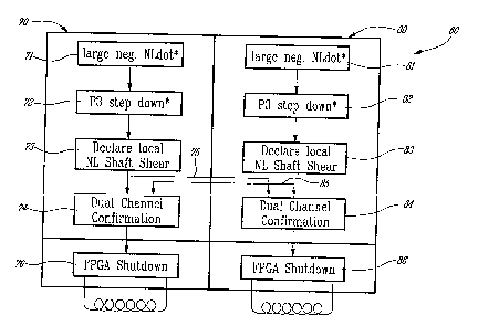
Figure 3 illustrates the logic sequence 60, which
can be utilized to immediately detect failure of the low
pressure compressor shaft. The logic sequence is
performed over two channels of a control processor known
as a "Full Authority Digital Engine Control" or "FADEC".
The FADEC is essentially a multi-channel on board
computer that receives a limited number of inputs from
the aircraft pilot as well as continuous input from the
various sensors, switches, and drivers that are placed
throughout the engine. The FADEC analyzes these various
inputs from these devices and sends control signals back
to these devices to manage their operation. FADEC
systems are well known in the art, and were first
disclosed in U.S. Patent 4,718,229 to Riley, issued on
January 12, 1988.
The FADEC of the preferred embodiment of present
invention is capable of performing a logic sequence that
takes inputs of NL and P3 pressure to determine whether a
shaft decouple has occurred.
One may choose to declare a shaft failure on the
basis of the NLDot calculated from samples of NL;
however, a more robust system would confirm the shaft
failure by, for example, sensing ur.iusual corresponding
changes in P3. Preferably, in order to prevent
inadvertent shut down of the engine under conditions
where the shaft has not failed, the second parameter is
used to verify that a failure is taking place.
CA 02333996 2000-12-01
WO 99/64727 PCT/CA99/00517
13
It has been experimentally found that a parameter
which changes rapidly during low pressure compressor
shaft failure is the pressure at the entrance of the
combustion chamber, referred to by the parameter "P3".
This pressure is measured in the region of the engine
between the downstream end of the high pressure
compressor blades and the entrance to the combustion
chamber. Experiments have demonstrated that a drop in
the P3 pressure corresponds with shaft failure condition.
Thus, parameter can be measured as a backup to verify any
detection of shaft failure made by measuring sudden
decelerations in the low speed compressor. Of course,
other physical parameters equally affected by such
failure may be measured as an alternative to the P3
parameter. For the purpose of the following description
the invention will be described as incorporating the
measurement of the P3 parameter within the logic
sequence.
The input for deceleration can be derived from
rotational speed sensors placed near the input end of the
low pressure compressor blade section, or placed near the
shaft for the low pressure compressor. Changes in
rotational speed transmitted to the FADEC may be used to
calculate acceleration or deceleration by the FADEC
system. The P3 pressure is derived from pressure sensors
placed at the entry of the combustion section, measuring
absolute pressure in this area. One set of rotational
CA 02333996 2000-12-01
WO 99/64727 PCT/CA99/00517
14
speed and pressure sensors communicate with one channel
of the FADEC, while a second set of rotational speed and
pressure sensors communicate with a second, backup
channel of the FADEC.
Figure 3 shows the first FADEC channel 70
communicating with sensor inputs for NL 71 for
calculating NLDot and P3 pressure drop 72. The logic
sequence is as follows:
(1) The FADEC will sample the rotational speeds, and
calculate normalized NLDot on one of the communications
channels at about 20 millisecond intervals. The actual
time interval between sampling may vary, but in the
preferred embodiment, the sample time interval is
between 20-30 milliseconds.
(2) If the calculated normalized NLDot exceeds the
line of demarcation for normalized NLDot (derived from
the graph of Fig. 2) in several consecutive samples, then
this parameter will be set and the logic sequence will
move on to testing P3. In the preferred embodiment,
three successive samples of NL and calculations of NLDot
will set the parameter, but a differing number of
successive samples may be taken, such as one sample, or
four or more samples.
(3) If the P3 value is below the predicted value for
P3 under those particular engine operating conditions,
then the logic will declare a shaft shear condition. In
the preferred embodiment, the shaft shear condition is
CA 02333996 2000-12-01
WO 99/64727 PCT/CA99/00517
declared when the P3 value is 20psia or more below the
predicted value. However, the difference between the
measured P3 and the predicted P3 necessary to declare a
shaft failure may vary, such as would be understood by
5 the person of ordinary skill in the art.
(4) If the logic declares a shaft shear, than
confirmation of the finding is made by sending a
signal 75 to backup channel 80, which is simultaneously
performing the same sampling and comparison tests 81-83,
10 that are being performed on channel 70. If channel 80
verifies the outcome, it sends a signal 85 back to
channel 70, and both channels send signals for engine
shutdown.
(5) Both channels will then agree and send signals
15 to Field Programmable Gate Array Circuits (FPGA's) 76
and 86 respectively, which receive the signals from
channels 70
and 80 and order a fuel cutoff to the engines, thus
immediately decelerating the engine displaying the shaft
shear condition.
The advantage of this logic sequence is threefold:
(1) The logic sequence is capable of declaring and
verifying a shaft failure in a total time of about 80-100
milliseconds, depending upon the exact processing speed
of the FADEC. Given the fact that fragmentation by the
turbines downstream of the failure occurs less than one
second after the shaft failure, the response time of 50-
CA 02333996 2000-12-01
WO 99/64727 PCT/CA99/00517
16
60 milliseconds gives the FADEC system the ability to
shut down the engine before extensive damage is caused to
the engine.
(2) The logic sequence and FAADEC processor responds
more rapidly to the failure than any human controller
could ever respond. If the information on normalized
NLDot and P3 were sent a to a pilot in a cockpit, even if
the pilot were warned by a warning light of a sensed
failure, the response time would be at least 5-25
seconds, which is not sufficiently fast to prevent damage
to the engine. The logic sequence disclosed herein can
be performed and executed in a time frame that is faster
than normal human reflexes, and fast enough to prevent
extensive damage to the engine or damage to the fuselage
resulting from uncontained failure.
(3) The logic sequence utilizes multiple backups and
logic agreements to prevent engine shut down under
spurious conditions. The design of verifying normalized
NLDot with multiple successive samples, the use of the P3
parameter for secondary confirmation, and the
communication with a second channel for tertiary
confirmation, all serve to prevent engine shut down
unless all the data points to a shaft failure. This
prevents the engine from being shutdown under spurious,
or unpredictable conditions which are not the result of
shaft failure. Ultimately, this permits safe usage of
CA 02333996 2000-12-01
WO 99/64727 PCT/CA99/00517
17
the logic system under a variety of different flight
conditions.
Figure 4 illustrates the system as it operates when
one of the two channels communicating with the FADEC is
not available. This might occur when one of the channels
is not able to communicate with one of the sensors, or
the channel has failed to connect with the FADEC
processor. In figure 4, channel 70 is the operational
channel, while channel 60 is the channel which is not
functioning. In this mode of operation, the steps of
checking an excessive NLDot 71, checking the P3 step
down 72 and declaring the shaft shear failure 73 occur as
normal. However, when the channel 60 is not available,
it defaults to "Confirmed" status and confirms the
conclusion reached on channel 70. The advantage of such
a logic sequence is that the aircraft does not have to be
taken out of service to repair the failure on the out of
service channel 60 since the other channel 70 remains
operable, and performs all the necessary steps for
determining shaft failure. As a result, the aircraft is
able to extend its "in-service" time while still
performing the necessary failure checks.
Figures 1-4 are addressed to logic sequences which
are preferred for use when the aircraft engine is fully
running, such as would occur during flight at a cruise
altitude or during take off. However, other logic
sequences are preferably used during the initial start up
CA 02333996 2000-12-01
05-09-2000 CA 009900517
- 18 -
of the engine, and the sub-idle run up of the engine.
These logic sequences are illusitrated in Figure 5.
Figure 5 illustrates the logic sequence
which is employed when the engine goes through its
initial start up after ignition. "NH" represents the
rotational velocity of the high. speed compressor while
"XV represents the percent of velocity achieved by
the high speed compressor in comparison to the maximum
full throttle velocity for this compressor. "NL"
represents the rotational velocity of the low speed
compressor while "Minimum%" represents the percent of
velocity achieved by the low speed compressor in
comparison to the full throttle velocity. The actual
values for the parameters X% and Minimum% will vary
depending upon the type and design of engine involved,
as would be understood by the person of ordinary skill
in the art.
However, the Minimum% is always a function
of the X%. In the preferred embodiment of the
invention, where the logic sequence is applied to a
turboprop engine, such as the type known as "PW150A",
the preferred X% is between, about 61% to 64%,
representing between 19,000 and 20,000 RPM's. For
this particular X%, the Minimtun is between 27% and
28%, representing 7500 to 7510 RPM's.
The logic sequence of Figure 5 operates by
first testing the value for NH and assigning it a
.percentage of
AMENDED SHEET
CA 02333996 2000-12-01
WO 99/64727 PCT/CA99/00517
19
maximum RPM (X%). The value of NL is then tested and
assigned a percentage of maximum RPM (Minimum%). If the
Minimum% of RPM for the low speed compressor is not met
for each value of X% of the high speed compressor
measured at preferably three 20 millisecond intervals,
than the engine start is aborted by shutting off fuel to
the engine.
The logic sequence for the run up portion of the
start prior to idle is essentially the same as that used
for the initial start as shown in figure 5. NH is
measured and assigned a value (X%) and NL is measured and
assigned a value (Minimum%). If the Minimum% of RPM for
the low speed compressor is not met: for each value of X%
of the high speed compressor, with measurements taken at
multiple intervals, the engine start is aborted by
shutting off fuel flow to the engine.
While the invention has been shown and described
with respect to specific embodiments thereof, this is for
the purpose of illustration rather than limitation, and
other variations and modifications of the specific
embodiments herein shown and described will be apparent
to those skilled in the art within the intended spirit
and scope of the invention as set forth in the appended
claims.