Sélection de la langue

Search

Sommaire du brevet 2334309 

Énoncé de désistement de responsabilité concernant l'information provenant de tiers

Une partie des informations de ce site Web a été fournie par des sources externes. Le gouvernement du Canada n'assume aucune responsabilité concernant la précision, l'actualité ou la fiabilité des informations fournies par les sources externes. Les utilisateurs qui désirent employer cette information devraient consulter directement la source des informations. Le contenu fourni par les sources externes n'est pas assujetti aux exigences sur les langues officielles, la protection des renseignements personnels et l'accessibilité.

Disponibilité de l'Abrégé et des Revendications

L'apparition de différences dans le texte et l'image des Revendications et de l'Abrégé dépend du moment auquel le document est publié. Les textes des Revendications et de l'Abrégé sont affichés :

  • lorsque la demande peut être examinée par le public;
  • lorsque le brevet est émis (délivrance).
(12) Brevet: (11) CA 2334309
(54) Titre français: SCIERIE PORTABLE
(54) Titre anglais: PORTABLE SAWMILL
Statut: Périmé et au-delà du délai pour l’annulation
Données bibliographiques
(51) Classification internationale des brevets (CIB):
  • B27B 25/10 (2006.01)
  • B23D 47/02 (2006.01)
  • B23D 47/04 (2006.01)
  • B23D 53/06 (2006.01)
  • B27B 29/08 (2006.01)
(72) Inventeurs :
  • TAMMI, PASI (Finlande)
(73) Titulaires :
  • TOMMI LAINE TRADING OY
(71) Demandeurs :
  • TOMMI LAINE TRADING OY (Finlande)
(74) Agent: GOWLING WLG (CANADA) LLP
(74) Co-agent:
(45) Délivré: 2008-08-05
(86) Date de dépôt PCT: 1999-06-09
(87) Mise à la disponibilité du public: 1999-12-16
Requête d'examen: 2003-11-18
Licence disponible: S.O.
Cédé au domaine public: S.O.
(25) Langue des documents déposés: Anglais

Traité de coopération en matière de brevets (PCT): Oui
(86) Numéro de la demande PCT: PCT/FI1999/000497
(87) Numéro de publication internationale PCT: FI1999000497
(85) Entrée nationale: 2000-12-07

(30) Données de priorité de la demande:
Numéro de la demande Pays / territoire Date
981341 (Finlande) 1998-06-11

Abrégés

Abrégé français

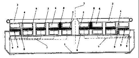
La scierie portable de présente invention est constituée, d'une part d'une structure de bâti (1), d'autre part d'une lame de scie (3) montée sensiblement verticalement par rapport à la structure du bâti, et enfin de plateaux-navettes (2) coopérant de part et d'autre du plan de la lame de scie. Ces plateaux-navettes exécutent des mouvements de va-et-vient sur la structure de bâti (1), parallèlement au plan de la lame de scie (3). Des réducteurs de frottement équipent le chemin de va-et-vient des plateaux-navettes (2) dans le sens du plan de la lame de scie, au niveau de cette lame (3). Selon l'invention, les réducteurs de frottement sont des surfaces de patin fixes (5), et notamment des rails-glissières ou des corps de patin disposés en série sur le chemin de va-et-vient des plateaux-navettes.


Abrégé anglais


The present invention relates to a portable sawmill with a frame structure (1)
and a saw blade (3) extending essentially vertically
upwards in relation to the frame structure, tables (2) cooperating on both
sides of the saw line of the saw blade and reciprocating on the
frame structure (1) parallel with the saw blade (3), wherein there are
friction reducing means on the path of the tables (2) by means of
which the tables are movable to and from in the direction of the saw line by
the saw blade (3). According to the invention, the friction
reducing means used are fixed sliding surfaces (5), such as slide rails or
sliding bodies arranged sequentially on the table path.

Revendications

Note : Les revendications sont présentées dans la langue officielle dans laquelle elles ont été soumises.


The embodiments of the invention in which an exclusive property
or privilege is claimed are defined as follows:
1. Portable sawmill comprising:
- a frame structure (1),
- a saw blade (3) extending essentially vertically upwards in relation to the
frame structure,
- tables (2) cooperating on both sides of a saw line of the saw blade and
reciprocating on the frame structure (1) parallel with the saw blade (3), and
- friction reducing means on a path of the tables (2) by means of which the
tables are movable to and from in the direction of the saw line by the saw
blade
(3),
characterized in that the friction reducing means are fixed sliding surfaces
(5).
2. The portable sawmill of claim 1, characterized in that the sliding surfaces
(5)
are slide rails extending substantially in the same direction as the path of
the
tables.
3. The portable sawmill of claim 1, characterized in that the sliding surfaces
(5)
comprise several sliding bodies arranged sequentially on the table path.
4. The portable sawmill of any one of claims 1 to 3, characterized by sliding
surfaces being mounted on one of: an upper surface of the frame structure, a
lower surface of the tables, or both, with the lower surface of the tables
contacting the sliding surfaces at all time.
5. The portable sawmill of claim 4, wherein the upper surface of the frame
structure (1) comprises the sliding surfaces (5), characterized by channels
(7)
entering into the sliding surfaces and connected to a source of lubricant for
lubricating the sliding surfaces (5).

6. The portable sawmill of claim 4, wherein the upper surface of the frame
structure (1) comprises the sliding surfaces (5), characterized by channels
(7)
entering into the sliding surfaces and being connected to a source of
pressurized air in order to create a friction reducing air cushion on the
sliding
surfaces (5).
7. The portable sawmill of any one of claims 4 to 6, characterized by the
sliding
surfaces comprising a first set of guiding means, the lower surface of the
tables
comprising a second set of guiding means cooperating with the first set of
guiding means for guiding the tables in alignment with the saw blade during
reciprocating movement.
8. The portable sawmill of any one of claims 1 to 7, characterized in that the
sliding surfaces (5) are of slippery plastic, including Nylon, Teflon, and
polyethylene.

Description

Note : Les descriptions sont présentées dans la langue officielle dans laquelle elles ont été soumises.


CA 02334309 2000-12-07
WO 99/64212 PCT/F199/00497
Portable sawmill
The present invention relates to a portable sawmill and particularly
such a portable sawmill which has a saw blade, such as a band or
circular saw blade extending essentially vertically upwards in relation
to its frame structure, with tables cooperating on both sides of the saw
line of the saw blade and reciprocating on the frame structure parallel
with the saw blade, wherein friction reducing means are provided on
the path of the tables by means of which the tables are movable to
and from in the direction of the saw line by the saw blade.
There are previously known portable sawmills of the type mentioned
in the introduction, in which the tables are movable with rolls mounted
on bearings transversely in relation to the path of the tables, the rolls
being provided substantially on the whole length of the path of the
tables. By means of the rolls, even a heavy timber can be easily
moved on the tables by means of a hydraulic traction motor coupled
to the tables.
A disadvantage of these portable sawmills of prior art is e.g. the high
noise level when the tables hit the rolls in front of them when moving.
Another disadvantage is the jumping movement of the tables when
they are transferred from one roll to another, which, with time, bends
the tables and makes the use of the portable saw more difficult.
Furthermore, the heavy tables moving on the rolls constitute a safety
risk, as the user's hand may be displaced between a roll and the end
of a table and authorities demand the safety risk to be eliminated.
Also, the rolls with their bearings and bearing supports increase the
production costs and weight of the portable sawmill.
It is an aim of the present invention to eliminate the above-mentioned
disadvantages, and this is achieved according to the present invention
by replacing the above-mentioned rolls with their bearings and
bearing supports primarily with fixed sliding surfaces.

CA 02334309 2000-12-07
WO 99/64212 PCTIFI99/00497
2
On fixed sliding surfaces, tables are moved lightly and without noise.
The risk that the user's hand could be displaced between the end of a
table and the sliding surfaces no longer exists. Furthermore, the
sliding rails are cheaper than the rolls with their bearings and bearing
supports and also considerably lighter in weight. The tables are
moved on the sliding surfaces smoothly without jumping, wherein the
tables remain in their original straight shape. Moreover, the sliding
surfaces facilitate the mounting of various additional devices in the
portable sawmill and make it possible to develop them further.
The sliding surfaces can be composed of slide rails substantially
parallel to the path of the tables, or several separate sliding bodies
arranged one after the other substantially in the direction of the path
of the tables. Sliding surfaces can be provided on the upper surface of
the frame structure or on the lower surface of the tables or on both,
substantially on the whole length.
To reduce the friction of the sliding surfaces, the portable sawmill can
be equipped with channels entering into the sliding surfaces and con-
nected to a source of lubricant for lubricating the sliding surfaces or to
a source of pressurized air in order to create a friction reducing air
cushion on the sliding surfaces. Alternatively, or in addition, it is
possible to use magnets which push each other away to create a
magnetic buoyancy for the tables.
To guide the tables during their reciprocating movement, the sliding
surfaces can be equipped with recesses, protrusions or brackets
extending on the table paths, wherein on the upper surface of the
frame structure or on the lower surface of the tables there are at
corresponding places protrusions, brackets or recesses compatible
therewith.
The sliding surfaces are preferably of some slippery plastic, such as
Nylon, Teflon, polyethylene or the like.

CA 02334309 2000-12-07
WO 99/64212 PCT/F199/00497
3
In the following, the invention will be described in more detail with
reference to the appended drawing which shows a cross-section on a
preferred embodiment of the invention.
In the drawing, the frame structure of a portable sawmill is generally
indicated with reference numeral 1, tables movable above the frame
structure 1 in its longitudinal direction with reference numeral 2, and a
saw blade arranged between the tables 2, vertically in relation to the
frame structure 1, with reference numeral 3, the saw line of the saw
blade indicated with a broken line between the tables 2, wherein the
tables 2 move in alignment with the saw blade 3 on both sides of the
saw line. The mechanism for movement of the tables 2 is not shown
in the drawing, because it has a conventional construction.
The lower surface of the tables 2 and, correspondingly, the upper
surface of the frame structure 1 are provided with superimposed
streamline tubes 6 at a transverse distance from each other, the
streamline tubes 6 extending in the longitudinal direction of the frame
structure 1, i.e. in the direction of the path of the tables 2.
The upper surface of the lower streamline tubes 6 fixed to the frame
structure 1 is provided with sliding bodies 5 of equal width, arranged
sequentially in the longitudinal direction of the lower streamline tubes
6 at a short distance from each other along the whole length of the
path of the tables 2. The sliding bodies 5 closest to the saw line of the
saw blade 3 have a cross-section of an upside down T, the abutment
extending over the whole width of the inner pairs of streamline tubes
and the upwards directed branch 8 extending between the
corresponding upper pairs of streamline tubes 6.
Furthermore, both of the opposite sides of the frame structure 1 are
provided with a metal profile 9, whose upper surface that is higher
than the frame structure 1 is provided with a sliding body 5 with an L-
shaped cross-section, the abutment of the sliding body 5 being fixed
to the upper surface of the metal profile 9 and the inner leg extending
downwards along the outer surface of the inner wall of the metal
profile 9. Moreover, the lower surface of the outer streamline tube 6 in

CA 02334309 2000-12-07
WO 99/64212 PCT/F199/00497
4
both tables 2 is provided with an angle iron 4 which has a
corresponding shape and direction and, together with the upwards
directed branches 8 of the sliding bodies 5 closest to the saw line of
the saw blade 3, guides the tables 2 during their movement.
In addition, the frame structure 1 is provided with channels 7 for a
lubricant or pressurized air, the channels 7 entering into the upper
surface of each sliding body to reduce friction between the sliding
bodies 5 and the upper streamline tubes 6 as well as the angle irons
4.
The sliding surfaces are preferably of some slipper plastic, such as
Nylon, Teflon, polyethylene or the like. Instead of the sliding bodies, it
is equally possible to use slide rails extending in the path of the tables
and having the length of the path. Sliding surfaces can also be
provided on the lower surfaces of the upper streamline tubes, but it is
structurally simpler to supply a lubricant or pressurized air into sliding
surfaces in the lower streamline tubes.
It is obvious for anyone skilled in the art that the present invention can
also be modified in other ways within the scope of the appended
claims. Consequently, it is also possible to use conventional rolls in
addition to sliding bodies or rails.

Dessin représentatif
Une figure unique qui représente un dessin illustrant l'invention.
États administratifs

2024-08-01 : Dans le cadre de la transition vers les Brevets de nouvelle génération (BNG), la base de données sur les brevets canadiens (BDBC) contient désormais un Historique d'événement plus détaillé, qui reproduit le Journal des événements de notre nouvelle solution interne.

Veuillez noter que les événements débutant par « Inactive : » se réfèrent à des événements qui ne sont plus utilisés dans notre nouvelle solution interne.

Pour une meilleure compréhension de l'état de la demande ou brevet qui figure sur cette page, la rubrique Mise en garde , et les descriptions de Brevet , Historique d'événement , Taxes périodiques et Historique des paiements devraient être consultées.

Historique d'événement

Description Date
Le délai pour l'annulation est expiré 2014-06-10
Lettre envoyée 2013-06-10
Accordé par délivrance 2008-08-05
Inactive : Page couverture publiée 2008-08-04
Requête visant une déclaration du statut de petite entité reçue 2008-04-16
Déclaration du statut de petite entité jugée conforme 2008-04-16
Préoctroi 2008-04-16
Inactive : Taxe finale reçue 2008-04-16
Un avis d'acceptation est envoyé 2007-11-21
Lettre envoyée 2007-11-21
Un avis d'acceptation est envoyé 2007-11-21
Inactive : Approuvée aux fins d'acceptation (AFA) 2007-08-13
Modification reçue - modification volontaire 2007-06-04
Inactive : Dem. de l'examinateur par.30(2) Règles 2007-03-02
Modification reçue - modification volontaire 2006-09-06
Inactive : CIB de MCD 2006-03-12
Inactive : Dem. de l'examinateur par.30(2) Règles 2006-03-06
Lettre envoyée 2003-12-03
Toutes les exigences pour l'examen - jugée conforme 2003-11-18
Exigences pour une requête d'examen - jugée conforme 2003-11-18
Requête d'examen reçue 2003-11-18
Inactive : Page couverture publiée 2001-03-30
Inactive : CIB en 1re position 2001-03-18
Inactive : Notice - Entrée phase nat. - Pas de RE 2001-03-08
Lettre envoyée 2001-03-08
Demande reçue - PCT 2001-03-07
Déclaration du statut de petite entité jugée conforme 2000-12-07
Demande publiée (accessible au public) 1999-12-16

Historique d'abandonnement

Il n'y a pas d'historique d'abandonnement

Taxes périodiques

Le dernier paiement a été reçu le 2008-05-26

Avis : Si le paiement en totalité n'a pas été reçu au plus tard à la date indiquée, une taxe supplémentaire peut être imposée, soit une des taxes suivantes :

  • taxe de rétablissement ;
  • taxe pour paiement en souffrance ; ou
  • taxe additionnelle pour le renversement d'une péremption réputée.

Les taxes sur les brevets sont ajustées au 1er janvier de chaque année. Les montants ci-dessus sont les montants actuels s'ils sont reçus au plus tard le 31 décembre de l'année en cours.
Veuillez vous référer à la page web des taxes sur les brevets de l'OPIC pour voir tous les montants actuels des taxes.

Historique des taxes

Type de taxes Anniversaire Échéance Date payée
Taxe nationale de base - petite 2000-12-07
Enregistrement d'un document 2000-12-07
TM (demande, 2e anniv.) - petite 02 2001-06-11 2001-06-07
TM (demande, 3e anniv.) - petite 03 2002-06-10 2002-05-23
TM (demande, 4e anniv.) - petite 04 2003-06-09 2003-05-23
Requête d'examen - petite 2003-11-18
TM (demande, 5e anniv.) - petite 05 2004-06-09 2004-05-18
TM (demande, 6e anniv.) - petite 06 2005-06-09 2005-05-16
TM (demande, 7e anniv.) - petite 07 2006-06-09 2006-05-09
TM (demande, 8e anniv.) - petite 08 2007-06-11 2007-05-28
Taxe finale - petite 2008-04-16
TM (demande, 9e anniv.) - petite 09 2008-06-09 2008-05-26
TM (brevet, 10e anniv.) - petite 2009-06-09 2009-05-19
TM (brevet, 11e anniv.) - petite 2010-06-09 2010-05-10
TM (brevet, 12e anniv.) - petite 2011-06-09 2011-05-16
TM (brevet, 13e anniv.) - petite 2012-06-11 2012-06-07
Titulaires au dossier

Les titulaires actuels et antérieures au dossier sont affichés en ordre alphabétique.

Titulaires actuels au dossier
TOMMI LAINE TRADING OY
Titulaires antérieures au dossier
PASI TAMMI
Les propriétaires antérieurs qui ne figurent pas dans la liste des « Propriétaires au dossier » apparaîtront dans d'autres documents au dossier.
Documents

Pour visionner les fichiers sélectionnés, entrer le code reCAPTCHA :


Pour visualiser une image, cliquer sur un lien dans la colonne description du document. Pour télécharger l'image (les images), cliquer l'une ou plusieurs cases à cocher dans la première colonne et ensuite cliquer sur le bouton "Télécharger sélection en format PDF (archive Zip)" ou le bouton "Télécharger sélection (en un fichier PDF fusionné)".

Liste des documents de brevet publiés et non publiés sur la BDBC .

Si vous avez des difficultés à accéder au contenu, veuillez communiquer avec le Centre de services à la clientèle au 1-866-997-1936, ou envoyer un courriel au Centre de service à la clientèle de l'OPIC.


Description du
Document 
Date
(aaaa-mm-jj) 
Nombre de pages   Taille de l'image (Ko) 
Dessin représentatif 2001-03-29 1 16
Abrégé 2000-12-06 1 64
Description 2000-12-06 4 205
Revendications 2000-12-06 2 68
Dessins 2000-12-06 1 28
Revendications 2006-09-05 2 57
Revendications 2007-06-03 2 55
Dessin représentatif 2008-07-21 1 16
Rappel de taxe de maintien due 2001-03-07 1 112
Avis d'entree dans la phase nationale 2001-03-07 1 194
Courtoisie - Certificat d'enregistrement (document(s) connexe(s)) 2001-03-07 1 113
Accusé de réception de la requête d'examen 2003-12-02 1 188
Avis du commissaire - Demande jugée acceptable 2007-11-20 1 164
Avis concernant la taxe de maintien 2013-07-21 1 171
PCT 2000-12-06 7 267
Taxes 2002-05-22 1 30
Taxes 2006-05-08 1 38
Correspondance 2008-04-15 3 84
Taxes 2008-05-25 1 39