Note : Les descriptions sont présentées dans la langue officielle dans laquelle elles ont été soumises.
CA 02334762 2000-12-11
WO 99/64841 PCT/US99/13019
BACKSCATTER I'NSTRUMENT FOR MONITORING
PARTICULATE LEVELS IN A GAS STREAM
Field of the Invention
The invention relates to monitoring the amount. of
finely divided material in a fluid sample. More
particularly, the invention relates to monitoring the level
of particulates in a gas stream, for example, the dust in a
smokestack or duct associated with baghouse pollution
control equipment. The invention cietects backscattered
radiant energy as the means for monitoring particulate
levels.
Description of the Prior Art
Environmental considerations have given rise to
regulations requiring the monitoring of particulates in
smokestacks and ducts. Initial instrumentation efforts
consisted of transmissometers. A transmissometer is a
device that projects a beam of light through a particulate-
laden gas stream to a photodetector. The transmissiori of
the light is attenuated by the particulates. The degree of
attenuation is reported in terms of percent opacity. A
number of these devices were developed and installed on
smokestacks in the United States and elsewhere. These
devices are reliable for the measurement of the opacity of
particulates in a gas Stream when the opacity exceeds 5%.
Below 5% opacity these instruments are not reliable
CA 02334762 2000-12-11
WO 99/64841 PGT/US99/13019
indicators of gas streani particulates because of optical
i3lignment problems and linearity validation problems..
:Lndustrial transmissometers are costly, heavy, bulky, and
not suitable for the measurement of low dust levels in the
;5mall stacks and ducts from industrial air pollution control
4aquipment, particularly the small stacks and ducts
associated with baghouse-type pollution control equipment.
Scattering instruments have been developed that
ineasure the presence of ;particulates by projecting radiant
-energy into the gas stream and measuring the radiant energy
scattered by the particulate. These instruments do not have
alignment problems and have a high signal to noise ratio,
allowing very low particulate level measurement. These
instruments may be sidle scatter, forward scatter, or
backscatter.
Side scatter instruments project a beam of radiant
energy into the stack and collect the radiant energy from a
section of the beam with a lens that focuses the energy onto
a detector. Side scatter instruments have reduced
sensitivity to increasing particulate loading due to the
opacity of the gas stream between the beam section and the
receiving lens. Further, only a small portion of the stack
or duct is sampled resulting in incorrect assumptions of
particulates loading ac:ross the gas stream, unless the
particulates are evenly distributed (which rarely occurs).
Forward scatter instruments use a laser beam to
project into the gas stream and monitor the forward
- 2 -
CA 02334762 2000-12-11
WO 99/64841 PCT/US99/13019
scattered light from the particulates. These instruments
have an advantage in that they can determine the size of a
particle from the angle of the energy scattered by the
particle. The sample volume is very small reducing this
technique's utility. Because of size, weight and cost
considerations, forward scatter instruments are not suitable
for monitoring of dust levels in the small stacks and ducts
iassociated with industrial air pollution control equipment.
Back scatter instruments use a projected beam of
radiant energy that reflects off particles and is returned
to a detector. There is no attenuation of signal as the
level of particulate increases as the optical path to any
particle reflecting energy will be clear if the projected
beam and reflected energy are in the same path. Backscatter
instruments usually use a laser to project adequate energy
into the duct to assure a return signal. Reflections off
the opposing wall are a concern in the measurement process.
t9any of these instruments are bulky, costly, and heavy
rendering them unsuitable for measuring particulate levels
i_n the small stacks and ducts from industrial air pollution
control equipment.
The current practice in monitoring dust in the
stacks and ducts associated with baghouse-type pollution
control equipment is the use of monitors having non-optical
probes that extend into ttie stacks or ducts and generate a
nieasurement of particulate levels by the static charges that-
incident particles impart to the probe. These devices have
- 3 -
CA 02334762 2000-12-11
WO 99/64841 PCTIUS99/13019
the disadvantage of beinq operative only for use where the
particulates being measured hold a charge. Also, these
devices have reduced sensitivity and accuracy when the
surfaces of the probes become dirty. Probe-type devices as
described above are manufactured by Triboflow, Inc. (USA).
There is a neecl for an optical monitoring system
that may be used with relatively small diameter stacks and
ducts (for example, less than about five feet diameter) and
having particulates therein at opacity levels that are
relatively low (for example, less than about five percerit
(Dpacity) as is the condition in the case of various types of
:stacks and ducts associated with pollution control
equipment, particularly stacks and ducts associated with
baghouse-type equipment.
Summary of the Invention
In accordance with the present invention, there is
provided a low cost, lightweight solid state backscatter
particulate monitor that overcomes the difficulties
associated with current transmissometers and scattering
instruments. The monitor uses optically efficient design,
efficient light-to-digital signal detectors, embedded
nticrocontrollers, an air purge system containing no moving
niechanical parts and utilizes less than 2 watts. The
nionitor provides automatic setup, span and sample operations
suitable for measurement of particulates in a gas stream.
- 4 -
CA 02334762 2003-08-27
More specifically, the present invention provides a
backscatter instrument for monitoring the level of
particulates in a gas stream flowing through a stack or
duct, the backscatter instrument comprising a radiant
energy source for delivering a narrow beam of radiant
energy across the stack or duct through an opening in the
stack or duct wall, a lens positioned behind the radiant
energy source for receiving radiant energy backscattered
from particulates in the stack or duct and focusing the
radiant energy at a focal point, the radiant energy source
being positioned on the lens, a photodetector sensitive to
the band of radiant energy emitted by the radiant energy
source, the photodetector being located at or near the
focal point of the lens, means responsive to the radiant
energy incident on the photodetector for generating a
signal representative of the intensity of incident radiant
energy, and signal processing means for providing the
facility operator with an indication of the particulate
level in the gas stream.
The present invention also provides a backscatter
instrument for monitoring the level of particulates in a
gas stream flowing through a stack or duct, the backscatter
instrument comprising a radiant energy source for
delivering a narrow beam of radiant energy across the stack
or duct, a lens positioned behind the radiant energy source
for receiving radiant energy backscattered from
particulates in the stack or duct and focusing the radiant
energy at a focal point, the radiant energy source being
positioned on the lens, and a photodetector located at or
near the focal point of the lens.
The present invention also provides a method of
monitoring dust levels in a stack or duct associated with a
baghouse-type pollution control installation wherein the
-4 a-
CA 02334762 2003-08-27
stack or duct has a diameter of less than about five feet
and the fluid stream in the stack or duct, in normal
operation, has an opacity less than about 5%, the_method
comprising the steps of establishing a narrow beam of
radiant energy across the stack or duct, receiving
backscattered radiant energy on a single lens having a
focal point, the lens being positioned behind the radiant
energy source and secured thereto, detecting the intensity
of the backscattered radiant energy at or near the lens
focal point, generating a signal representative of the
intensity of the radiant energy at the lens local point,
and providing the system operator with an indication of the
particulate level in the gas stream.
-4 b-
CA 02334762 2000-12-11
WO 99/64841 PCT/US99/13019
In preferred embodiments, the monitor of the invention
establishes a transmitted beam of radiant energy into a gas
Stream that is reflected off particulates in the stream. The
ntonitor includes optics that concentrate the reflected
energy onto a detector that generates a signal
representative of the amount of energy reflected from the
particulates. The radiant energy source, preferably a source
of infrared energy, is turned off periodically and the
detector output is monitored for ambient energy. A- spanning
infrared emitting diode (IRED) is provided to periodically
illuminate the detector and determine proper instrument
operation. An embedded microprocessor sets up the monitor
automatically, processes the signal from the detector in
setup mode, ambient light mode, signal mode, and span mode.
The microprocessor monitors the condition of the instrument,
controls the functions of the source, the spanning light:
emitting diode, and determines the level of the
particulates.
In one embodiment, the invention is used as a
monitor to determine failure of air pollution control
equipment, for example, broken or leaking bags in baghouse
pollution control equipment. In this embodiment, the
monitor of the invention is mounted to a stack or duct and
serves to compare the backscatter level to established
levels when the gas stream is clean, determine acceptability
to established dust level values, and communicate
particulate level conditions to the facility operator. Four
- 5 -
CA 02334762 2000-12-11
WO 99/64841 PCT/US99/13019
conditions are indicated, preferably by using two contacts
on the monitor. Both contacts closed indicates that both
the monitor and particulate levels are acceptable. If both
contacts are open, either the monitor has failed or the
power is off. If only or.ie contact is closed, either a mid
level warning is indicated or a high level warning is
indicated, depending upon the contact.
In another embodiment, the monitor is used as a mass
particulate monitor where the microprocessor monitors the
condition of the instrument, controls the functions of the
source, the spanning light emitting diode, and provides an
output of monitor and particulate levels into the facility
data acquisition system. Signal output options include,
digital, voltage or amperage proportional to the instrument
backscatter signal.
Brief Description of the Drawings
Some of the objects having been stated, other
objects will appear as the description proceeds, when taken
in connection with the accompanying drawings, in which --
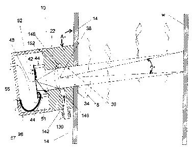
Figure 1 is a cross-sectional view of the
instrument as mounted to a duct.
Figure 2 is a flow chart showing the operation and
logic of the monitor used as a baghouse monitor that
communicates four states to the facility operator.
- 6 -
CA 02334762 2000-12-11
WO 99/64841 PCT/US99/13019
Figure 3 is a flow chart similar to Figure 2 for a
monitor used as a particulate mass concentration monitor
that communicates to the facility data acquisition system.
Figure 4 is a representation of the printed
circuit board that mounts the photodetector, microprocessor
and related components.
Figure 5 is a cross-sectional view of the filter
portion of the air purge system.
Detailed Desar-iption of the Invention
While the present invention will be described more
:fully hereinafter with reference to the accompanying
drawings, in which aspects of the preferred manner of
practicing the present invention are shown, it is to be
understood at the outset of the description which follows
that persons of skill in t:he appropriate arts may modify the
invention herein described while still achieving the
favorable results of this invention. Accordingly, the
ciescription which follows is to be understood as being a
broad, teaching disclosure directed to persons of skill i:n
the appropriate arts, and not as limiting upon the present
invention.
Referring to ttie drawings, and particularly to
Figure 1, there is shown a backscatter monitor 10
constructed in accordance with present invention, installed
on a smokestack 14 associated with pollution control
e:quipment such as a baghouse (not shown) As known in the
- 7 -
CA 02334762 2003-08-27
WO 99164841 PCT/1JS99/13019
art, smokestack 14 carries a gas stream that should have a
low particulate level due to dust having been removed from
the stream by the baghouse. However, when a bag leaks or
breaks in the baghouse, particulates in the gas stream rise
to an unacceptable level and it is essential that the
equipment operator be immediately notified of this condition
by a signal from monitor 10.
Monitor 10 is mounted to smokestack 14 by
conventional means known in the art, for example, by
provision of a window 18 in the side of stack 14 and mating
flange elements (not shown) that are located around window
18 and on monitor 10. Preferably, monitor 10 is mounted so
that its longitudinal axis is oriented at an angle A1 from
the stack which is in the range from about 100" to 110 ,
with an angle of about 102' having been found desirable. As
discussed in more detail below, the angular orientation of
monitor 10 assists in projecting the radiant beam into the
stack at a projection angle that minimizes the reflection of
radiant energy from the opposite stack wall W back to the
monitor. More particularly, the radiant energy beam
preferably is directed into smokestack 14 at an angle
greater than twice the beam spread to minimize the effects
of reflection off of the opposing wall surface.
Monitor 10 includes a cylindrical main body
portion 22 of plastic or metal, or other suitable material.
A cap portion 26 removably secures to main body portion 22 _
by latching-type fasteners, a threaded connection, or other
- 8 -
CA 02334762 2003-08-27
WO "/64841 PCT/US99/13019
suitable connection. Main body portion 22 includes a
central passage 30 opening to the interior of smokestack 14
and opening to the interior of cap 26. A lens 34 is mounted
in passage 30. A source of radiant energy is provided in
the form of an infrared light-emitting diode (IRED) 38 that,
in the illustrated embodiment, is secured to the center of
lens 34. The source may take other forms, such as fiber
optics. IRED 38 directs a narrow angle conical projection
of infrared energy into smokestack 14. The angle of
projection A2 preferably in the range from about 5 to 20 ,
with an angle of about 10 to 15 having been found
suitable. For use in a small stack (e.g., less than about
five feet diameter) environment at an installation.such as a
baghouse, IRED 38 may be a 0.081 milliamp device at a
wavelength in the near infrared. A suitable IRED for this
purpose is model number CLE-335 IRED manufactured by Clairex
of Plano, Texas (USA).
It will be appreciated that in the illustrated
embodiment, the entire monitor 10 is mounted to smokestack
14 at the mentioned angle A, in order to provide the desired
input direction for the radiant beam which is centered along
the longitudinal axis of monitor 10. However, monitor 10
may also be constructed such that the beam does not radiate
along the longitudinal axis of the monitor, in which case
the monitor would be mounted to the stack accordingly.
Monitor 10 also includes a printed circuit board
42 located within cap 26. Circuit board 42 is
- 9 -
CA 02334762 2000-12-11
WO 99/64841 PCTIUS99/13019
conventionally mounted by four posts 44 secured to main body
portion 22. Circuit boar=d 42 mounts a solid state infrared
photodetector 48 located at the focal point of lens 34 and
an embedded microcontroller 52, as well as other components
discussed below. Photodetector 48 preferably is a solid
state silicon pin photodetector model number 235 or 245,
nnanufactured by Texas Instruments (USA). Microcontroller 52
nlay take the form of a nlodel number BS-2 microcontroller;
nianufactured by Parallax, Inc. (USA).
The backscatter mode of particulate detection by
nionitor 10 operates as follows: Radiant infrared energy
emitted by IRED 38 is projected into the, gas stream of
smokestack 14 at an angle and with a beam spread as
described above. Infrared energy that is reflected off of
the opposite stack wall W predominately reflects back above
window 18 due to the indicated positioning of monitor 10 at
angle A1. Radiant energy that reflects or backscatters off
particulates within the gas stream in smokestack 14 and
which enters passage 30 is collected by lens 34 and focused
on photodetector 48. The amplitude of the detector response
is determined by the sum of the light reflected energy froni
the particulate matter, the reflected energy from the
opposite stack wali, and any radiant energy reflected inta
the system from outside. The signal is digitized,
preferably by an amplitude-to-frequency converter within
photodetector 48.
- 10 -
CA 02334762 2000-12-11
WO 99/64841 PCT/US99/13019
In one preferred usage of monitor 10 as a baghouse
rnonitor, microprocessor 52 communicates one of four states
to the facility operator according to a program stored in
the microcontroller. Figure 2 is a flow chart showing how
t:he four states are determined and communicated to the
facility operator in accordance with the level of
particulates incident on the photodetector. Referring to
F'igure 2, after monitor 10 is installed on stack 14, the two
switch contacts (discussed below) are connected to the
facility data system, and power is applied, and the
microprocessor queries for the existence of an - external
jumper to ground. If the jumper is in place, the instrument:
goes into startup mode.
In startup mode, source IRED 38 and the span IRED
5:1 are turned off. In this mode, photodetector 48 is only
receiving the ambient inf:rared energy in the stack. The
signal generated by the photodetector is current dependent
upon infrared energy level. The currerit is converted to
voltage by a transimpedence amplifier and to frequency
within the photodetector. Thus, the frequency is dependent
upon the level of infrared energy received from the duct:.
TIiis value is stored in random access memory as a declared
variable dark. Next the source IRED 38 is turned on by the
micro processor. Because tlae stack is clear of dust during
startup, the only infrared energy reflected back to the
photodetector is from the opposing wall of the stack. The
photodetector output is stored as "wall". The
- 11 -
CA 02334762 2000-12-11
WO 99/64841 PCT/US99/13019
microprocessor subtracts the value of dark from the value of
wall to determine the level of energy reflected from the
\opposing wall and stores this value as wall in an Eeprom.
The program loops back to the beginning to check the status
of the jumper. The program will stay in startup mode until
the jumper is removed.
After the jumper is removed (for example, by
simply cutting the jumper/lead)that may be located on the
terminal strip 57, the program moves to the spancheck and
sample functions.
The instrument now determines the dark level
across the duct with source and span IR emitting diodes
inactivated. This is stored as a variable dark in random
access memory. Next span 1 switch is activated energizing
the spanning diode through a resistor. The resistor value
determines the current and the energy output of span 1.
Typical span 1 resistor values are 1000 ohms. The detector
senses the span 1 value and provides a frequency signal to
the microprocessor. The program then subtracts the dark from
the span 1 signal and compares the difference to a
predetermined value to validate the sensor calibration. This
step is repeated for a different resistor (typically 2000
ohms) to give a lower span level. Again the difference
.between dark and span 2 is compared to a predetermined
number to validate a mid point calibration point for the
instrument.
- 12 -
CA 02334762 2000-12-11
WO 99/64841 PCT/US99/13019
If either of the span levels are unacceptable,
output switches one and two are turned off, and the LED 55
on the face of the monitor blinks very slowly, indicating
instrument fault. The program loops back to startup. As
long as a span fault is present, the loop will continue.
If the span levels are acceptable the main program
path (downward, Figure 2) is followed.
If all operational conditions are acceptable, the
monitor samples the dust level. The monitor again checks
the current dark level by turning off all sources and
spanning infrared diodes and sensing the level in the duct.
The infrared source is turried on, projecting infrared energy
into the duct where it is reflected off particulate and the
wall. Some energy (dark) ntay also enter the instrument from
the duct. The Eeprom wall value is retrieved. Dark and
wall are subtracted from the detector output to give a dust
value. The dust value is compared to predetermined
standards. There are three possibilities. The first is that
t:he dust level is high indicating an excessive level of
dust. In this case one of the switches is turned of f the
other on and the indicator LED 55 is flashed quickly. ThE:
second is that the dust level is slight indicating ari
moderate level of dust. In this case the switch conditions
are reversed and the indicator LED 55 is flashed slowly. If:
a:Lmost no dust is present, both switches are turned on and
the indicator LED 55 is turned on in a steady state. In any
oi' the three cases the instrument holds the switch
- 13 -
CA 02334762 2000-12-11
WO 99/64841 PCT/US99/13019
conditions for a short period of time (approximately 10
seconds) and the program loops back to the beginning
checking for jumper etc.
Figure 3 is a flow chart similar to Figure 2, but
showing the operation and logic of the monitor when used as
a particulate mass monitor. Referring to Figure 3, after
monitor 10 is installed on stack 14, the two switch contact
are connected to the fac:ility data system, and power is
applied, and the microprocessor queries for the existence of
an external jumper to ground. If the jumper is in place,
the instrument goes into startup mode.
In startup mode source IRED 38 and the span IRED
51 are turned off. In this mode, the photodetector is only
receiving the ambient infrared energy in the stack. The
signal generated by the photodetector is current dependent
upon infrared energy level. The current is converted to
voltage by a transimpede~nce amplifier and to frequency
within the photodetector. Thus the frequency is dependent.
upon the level of infrared energy received from the duct.
This value is stored in rzim as a declared variable "dark".
Next the source IRED 38 is turned on by the micro processor.
Because the stack is clear of dust during startup, the only
irifrared energy reflected back to the photodetector is from
ttie opposing wall of the stack. The photodetector output is
st:ored as "wall". The microprocessor subtracts the value of
dark from the value of wall. to determine the level of energy
re:flected from the opposing wall and stores this value in an
- 14 -
CA 02334762 2000-12-11
WO 99/64841 PCTIUS99/13019
Eeprom. The program loops back to the beginning to check the
status of the jumper. The program will stay in startup mode
until the jumper is removed. After the jumper is removed,
the program moves to the spancheck and sample functions.
The instrument now determines the dark level
across the duct with source and span diodes inactivated.
This is stored as a variable dark in random access memory.
Next span 1 switch is activated energizing the spanning
diode through a resistor. The resistor value determines the
current and the energy output of span 1. Typical span 1.
resistor values are 1000 ohms. The detector senses the span
1 value and provides a frequency signal to the
microprocessor. The prograrn then subtracts the dark from the
s;pan 1 signal and compares the difference to a predetermined
value to validate the sensor calibration. This step is
r-epeated for a different resistor (typically 2000 ohms) to
give a lower span level. Again the. difference between dark
and span 2 is compared to a predetermined number to validate
a mid point calibration.po:int for the instrument.
If either of the: span levels are unacceptable, a
digital span fault signal is transmitted to the data
acquisition system of the facility, and the LED on the face
of the instrument blinks very slowly, indicating instrument
fault. The program loops back to startup. As long as a span
fault is present, the loop will continue.
If the span levels are acceptable the main program
path (downward, Figure 3) is followed.
- 15 -
CA 02334762 2000-12-11
WO 99/64841 PCT/US99/13019
If all operational conditions acceptable, the
monitor samples the dust level. The instrument again checks
the current dark level by turning all sources and spanning
.
infrared diodes and sensing the level. in the duct. The
infrared source is turned on, projecting infrared enerqy
into the duct where it is reflected off particulate and the
wall. Some energy (dark) may also enter the instrument from
the duct. The Eeprom wall value is retrieved. Dark and
wall are subtracted from the detector output to give a dust
value. The dust value is outputted to a digital to analog
converter for the facility data acquisition system. Then the
program loops back to the beginning checking for jumper et:c.
Figure 4 is an illustration of the electronic
components on the circui.t: board. The main component is
microcontroller 52 that controls all of the functions of the
instrument. The microcontroller is programed using an
outboard computer 304 via a four wire serial interface 200.
The microprocessor controls the source IRED 38, the span
IRED 51, and the indicator LED 55, via a switching array
2:10. A setup jumper 212 external to the instrument is
connected to a port of the microcontroller. The external
contacts (discussed above) preferably are located ori
terminal strip 57 and are connected to the switching array
ttirough resistors 300 and 301, as shown. Current control to
span IRED 51 is controlled by resistors 220 and 222. Current.
through source IRED 38 is controlled through resistor 226.
When the instrument is used in a mass monitoring mode, three
-- 16 -
CA 02334762 2000-12-11
WO 99/64841 PCT/US99/13019
pins of the microcontroller output to a 12 bit digital to
analog converter 302 via a serial interface. Conve:rter 302,
in turn, communicates with the facility data acquisition
system 305. One port of microcontroller 52 has a wire 306
that connects to the facility data acquisition system 305 to
provide instrument status reports such as span faults.
Signal output from photodetector 48 to microcontroller 52 is
via a three wire interface.
Referring to Fiqure 5, there is shown the filter
portion 118 of an air purge system 120 that provides a
continuous flow of clean air across lens 34 to prevent a
buildup of opaque matter on the lens surface. Filter 1.18
may be located in close proximity to monitor 10 external of
the stack. In a preferrecl embodiment, air purge system 1.20
uses no moving parts and operates with a draft created by
the pressure differential between the ambient atmosphere and
the stack. In this embodiment, ambient air is drawn into
the input 121 of air filter 118 which contains a
conventional air filter medium 130 such as used for
z-utomobile carburetor products. Air exits medium 130 to a
plenum 134 from which it flows through a conduit 138.
Conduit 138 is connected to a conduit 139 on monitor 10 by a
f:lexible hose (not shown). Conduit 138 communicates with a
passage 142 in monitor main body portion 22. Passage 142
communicates with an annular cavity 146 that is also formed
in main body portion 22 surrounding the front face of lens
- 17 -
CA 02334762 2000-12-11
WO 99/64841 PCTIUS99/13019
31.1. Several small openings 152 (only two shown) extend froni
arinular cavity 146 open into central passage 30 just in
front of lens 34 and serve to continuously direct streams of:
clean air drawn through filter 118 across the front of the
lens. It will be appreciated that in those cases where the
pressure differential between the ambient atmosphere and the
stack does not create a sufficient draft, a fan or blower
may be used to provide the flow of clean air to the front.
face of lens 34. Alternatively, a clean compressed air
source may be used. In ariy event, the clean air should be
provided continuously in an amount sufficient to keep the
pztrticulates flowing through stack 14 from contacting lens
34. and accumulating thereon.
While the present invention has been described :in
connection with illustrated embodiments it will be
appreciated that modifications may be made without departing
from the true spirit and scope of the invention.
- 18 -