Note : Les descriptions sont présentées dans la langue officielle dans laquelle elles ont été soumises.
CA 02335066 2000-12-13
WE) 99/65434 PCT/US99/13384
-1-
SELF-ADHERING FRICTION REDUCING LINER AND
METHOD OF USE
BACKGROUND OF THE INVENTION
The present invention relates to the use of
very low friction material formed into patches or pieces
and adhered to the skin or to a surface in contact with
the skin (or immediately adjacent material such as a
sock) to lower the magnitude of tangential traction of
the surface in contact with the skin. The material
reduces the likelihood of abrasion, trauma and
ulceration in localized areas.
In the prior art, there have been efforts to
reduce the co-efficient of friction of materials in load
bearing contact with the skin, such as the surface"of a
lining of a shoe, which slides against a stocking. Also
the regions where a limb prosthesis is in load bearing
contact with a residual limb have been extensively
considered for ways of reducing problems. The co-
efficient of friction of smooth leather varies,
depending on the moisture content, and when it gets wet
can be quite high in friction. Moleskin patches have
been sold and used for covering corns on the feet, as
well as covering calluses, but this also has a
relatively high co-efficient of friction against the,
inner surface of a shoe and the co-efficient of
friction increases substantially when the moleskin is
wet.
Blisters, abrasions, calluses, bursas and even
some forms of sub-cutaneous tissue trauma are the result
of applications of a combination of forceful contact and
tangential tractions to the skin (forceful
rubbing/forceful shearing) High shear stresses may
CA 02335066 2000-12-13
WO 99/65434 PCT/US99/13384
-2-
cause damage in a single cycle. Low shear stresses may
cause tissue damage when the number of cycles is great.
Tangential skin tractions relate directly to
tissue shear stress and shear strain magnitudes. Shear
strain is by its very nature very distortional and, when
it exceeds certain levels, results in the tearing of
biological tissues such as blood capillaries and
interface (skin-.subcutaneous) layers. High normal
pressures (perpendicular to the skin surface) in the
absence of significant tangential tractions are
surprisingly well tolerated by skin and underlying
tissue, especially when applications are of a short
enough duration to avoid ischemic trauma (cell death
after an extended period of blood flow blockage).
This invention is primarily aimed at reducing
and preventing shear trauma from many repetitions of
short duration skin loadings, but eliminating shear
tractions even in low repetition, long-duration loadings
is of value.Research shows that even capillary blood
flow is affected strongly by whether or not shear
stresses are superimposed on normal pressures. When
high shear stresses are present, capillary blood flow
has been shown to be occluded at normal pressures only
half as great as what are required to occlude flow in
the absence of shear stresses and strains. There is some recognition among
medical
researchers and care-givers that shear plays a role in
tissue trauma. However, how and when excessive shear
stresses/strains occur and how they damage tissue are
hard to visualize. Injury from a normal force (a
simple, yet forceful, blow or bump causing injury by
crushing tissue) is easier for people to visualize and
understand. Shear stresses and how they vary over a
given area (and vary with time) are very hard to
CA 02335066 2000-12-13
WO 99/65434 PCT/US99/13384
-3-
measure; much harder than it is to measure normal
pressure. In addition to the visualization and
measurement difficulties just mentioned, there is the
fact that few people have better than a vague
qualitative awareness of how something called the
"coefficient of friction" (C.F.) relates to blisters,
abrasions, and 'calluses. Tangential traction force
magnitudes can be no greater than the C.F. times the
magnitude of normal force. Therefore, the simplest,
most direct way to reduce shear induced tissue trauma is
to choose materials which minimize friction against the
at-risk skin surface areas. Until the present
invention, there has been little practical awareness of,
and attention given to, friction management.
Examination and knowledge of products on the
market indicate that the opportunities for reducing
callusing, blistering and abrasions by friction
management has been almost entirely unappreciated by
designers of shoes, orthoses, prostheses, and many other
objects that come in repeated or prolonged contact with
the human body.
Thin silk or synthetic fiber sheets have been
used by amputees to pull over their residual limbs
before pulling on a cotton or wool sock and then donning
the limb prosthesis. The co-efficient of friction=
between the sheet and the sock is reduced under dry
conditions and does protect the residual limb to some
extent from friction and consequent shear-related
trauma. The coefficient of friction increases
substantially when the material becomes damp or wet. In
most cases, the material used to line shoes and
prosthetic sockets, for example, represent high friction
choices. Foam products are used to line prosthetic
sockets, orthoses, and shoe insoles and represent a
CA 02335066 2000-12-13
WO 99/65434 PCT/US99/13384
-4-
particularly poor material from the standpoint of
friction management. Damp skin and sock material
literally sticks to such foams.
Synthetic gel socket liners are available, and
these are generally in the range of 1/8 to 5/16 inch
thick. The liner cover tends to stick to the skin and
other materials in contact with it, so that it does not
act as a friction reducer, but does provide cushioning
and accommodates small amplitude shear motions without
much resistance. The effectiveness of a gel liner is
dependent on its thickness, and as it becomes thicker,
its weight and bulk are deterrents.
Thus, the concept of providing a very low
friction interface between the skin and surfaces that
contact the skin, particularly in high load and high
shear areas, has escaped the workers in the field and
the need exists for reduction of trauma to the skin
where the skin and tissue are supported.
SUMMARY OF THE INVENTION
The present invention relates to providing a
layer of material that has a very low friction outer
surface in both dry and wet conditions to provide an
interface with a surface that normally would support the
skin either directly or through a cloth covering, such
as a sock fabric. In the usual situation, the surface
loading or bearing on the skin may be the inner surface
of an orthosis, the socket surface of a prosthesis, or
inner surfaces of a shoe, especially insoles, but also
other inner surfaces. The layer of low-friction
material is adhered, preferably, to the surface of the
object that bears on the skin and faces the skin,
although applying the layer with an adhesive directly on
the skin in the affected area with the low friction
surface facing the support is also contemplated. The
CA 02335066 2000-12-13
WO 99/65434 PCTIUS99/13384
-5-
purpose of the low friction material is to lower the
magnitude of tangential tractions that the surface of
the object can exert against the skin.
The use of intervening layers is contemplated
in the present invention, so a sock or sheet placed
between the low friction pad and the skin does not
adversely affect the performance.
A low friction surface layer used may be on
material in the form of a sheet, or a small patch that
is pre-cut, or custom cut to a desired size, and having
a pressure sensitive adhesive on the surface of the
patch opposite from the low friction surface. The
adhesive may be on the outer surface of another layer of
material, such as a foam backing cushion layer or a
stretch fabric backing bonded to the low friction
material. A release paper is placed on the exposed
adhesive. When the release paper is removed, the patch
or piece of material providing the low friction surface
layer can be adhered into a certain desired position of
the surface of the skin or on the object that bears on
the skin.
Preferably, the low friction layer is a thin
film material having the surface friction
characteristics of polytetrafluoroethylene (PTFE) The
PTFE layer is preferably bonded to a fabric layer of a
somewhat elastic, flexible material such as Lycra or a
Lycra blend. The exposed side of the fabric is covered
with a pressure adhesive and a release paper is on top
of the adhesive.
The thin sheet of PTFE material can be used
without any backing sheets by applying adhesive directly
to the PTFE layer. Bonding a very thin sheet of PTFE to
a stretch fabric without having the PTFE separate from
the fabric during use gives the desired low friction
CA 02335066 2000-12-13
WO 99/65434 PCT/US99/13384
-6-
characteristics of the outer surface, while permitting
the formed patch to conform to irregular shapes or
surfaces, because of the stretch fabric underneath the
thin layer of PTFE. The stretch fabric also gives the
thin layer of low friction material, such as PTFE,
"body" so it can be handled reasonably during the
release paper stripping and application of the layer or
patch to the desired surface. Very thin layers of PTFE
tend to wrinkle or fold and cause problems with getting
them very smooth. The elasticity of the backing fabric
allows conformance into recesses, over convexities, and
onto a combination of compound contoured surfaces.
Cushioning material, such as foam can be placed
between the patch and the surface supporting the patch,
if desired, to provide a cushioning effect, as is known.
Various shapes can be made, including shapes which would
have the stretch fabric toward the center of the patch
or piece so that it was surrounded by an adhesive coated
thin low friction material.
A preferred method of use includes placement
of suitable size pieces or patches of the low friction
coefficient material either on the skin or on the
surface that will be next to the skin in locations where
shear trauma is likely to occur. These patches or
pieces can be held in place with suitable adhesive on the back side of the low
friction material. Foam or
other compressible material for cushioning can be used
wherever needed.
Another aspect or form of the protective patch
is the PTFE film or layer bonded to a calf skin leather
hide, textile foam liner, or other material that could
be used to line the inner wall of the toe box of a shoe.
The composite material can be sewn and applied in the
same manner as the lining material now is applied
CA 02335066 2000-12-13
WO 99/65434 PCT/US99/13384
-7-
without a PTFE film surface. The usefulness- of this
material is realized in its ability to shield dorsal and
peripheral surfaces of the foot from damaging shear
forces. At these non-plantar locations, high tangential
tractions can be present, but more often trauma develops
from lower forces, that generate excessive callus/corn
growth and/or tissue breakdown by the action of cyclic
(high frequency) loading.
The patches of the present invention offers an
easy way to accomplish "friction management". The
surfaces that a shoe, orthosis, or prosthesis present to
the skin vary as to their function and as to the tissue
trauma risk they present. It is also true that some
areas of the anatomy within a shoe, prosthesis, or
orthoses are at greater or lesser risk because' of the
level of peak forces and/or the amount of soft tissue
interposed between- skin and bone. Some parts of an
orthosis bear only slightly or not at all against the
corresponding skin surface. Other parts bear very
firmly in order to provide maximum orthopedic support,
correction, or weight bearing. Still other surfaces
such as the supra-condylar parts of a BK (lower leg)
prosthesis socket serve to suspend (during swing-
through) or maintain position of the device.
All of these just-noted facts are important=
because they are reasons to vary the friction
coefficient depending on the surface function. For
instance, there is very little reason to be concerned
about the friction coefficient of a surface in only very
light contact with the skin (unless the number of
repetitions is very high). Forceful cyclical contact
against a skin surface is a situation that benefits more
from minimizing the friction coefficient. If the area
is "bony" minimizing friction becomes more important.
CA 02335066 2000-12-13
WO 99/65434 PCT/US99/13384
-8-
In a case like the supra-condylar suspension
areas of the BK socket mentioned earlier, high friction
(even "sticky") materials may be desired. Applying the
low friction patches of an aspect of the invention to
certain areas and not others is a way to add friction
management to the orthotist's (prosthetist's,
podiatrist's, etc.) treatment methods and appliances.
In cases where the professional wishes to apply maximum
supportive/corrective pressure the near elimination of
friction and shear in selected regions means that much
greater support can be safely provided without
approaching tissue trauma conditions.
There are also many consumer (non-
professional) applications for the present invention.
Many people are plagued by excessive callus build-up.
A person with excessive calluses under the metatarsal
heads might remove~ the shoe insoles and apply low
friction patches to the corresponding surface of the
insole. If the excessive callus is in the form of
"corns", the person could apply a low friction corn pad
to relieve some pressure on a painful corn (by means of
annular cushioning material) and greatly reduce the
friction and shear which originally generated, and then
maintains the corn callus.
A similar but much larger patch might be applied by a skater over ankle bones
to allow tight (er)
lacing with greater comfort and less chance of trauma at
the apices of those bony prominences. As an
alternative, the skater may choose to adhere the patch
to the appropriate locations on the inside surface of
the skate uppers. There are a myriad of other
possibilities such as on kneeling pads (for cement
workers, etc.) or on backpack shoulder straps.
CA 02335066 2000-12-13
WO 99/65434 PCT/US99/13384
-9-
A similar (but non-consumer) use-- of the
cushioned patch (continuous, annular, or donut types) is
in hospitals for prevention of bed sores. Low friction
cushion patches of the present invention applied over
healthy bony areas such as sacrum-coccyx, greater
trochanter, heels, and elbows as a prophylactic measure
act to inhibit the generation of bed sores.
BRIEF DESCRIPTION OF THE DRAWINGS
Figure 1 is a plan view of a layer of material
made with a low friction surface material according to
the present invention;
Figure 2 is a sectional view taken on line 2--
2 in Figure 1 showing the layers used;
Figure 3 is a plan view of a form of patch;
Figure 4 is a sectional view of a patch made
according to an aspect of the present invention, taken
on line 4--4 in Figure 3 including a layer of low
friction material that will lower friction loads on the
skin in a selected area;
Figure 5 is a cross sectional view of a
modified aspect of the present invention;
Figure 6 is a plan view of a further modified
patch made according to the present invention;
Figure 7 is a sectional view taken on line 7--
7 in Figure 6; Figure 8 is a plan view of a further modified
patch made according to the present invention;
Figure 9 is a sectional view of the patch
shown in Figure 8 taken on line 9--9 in Figure 8;
Figure 10 is a schematic representation of a
typical shoe showing regions having patches made
according to the present invention installed for
reducing shear damage to tissue;
CA 02335066 2000-12-13
WO 99/65434 PCT/US99/13384
-10-
Figure 11 is a perspective view of-an ankle
and foot orthosis showing locations where patches having
a low friction surface according to the present
invention are installed, and which can be installed
either on the orthosis as shown, or as shown in Figure
12 on a foot on which the orthosis will be worn;
Figure 12 is a schematic showing of a foot and
ankle indicating desired locations of low friction
patches for an orthosis;
Figure 13 is a top plan view of a prosthetic
socket for a lower leg prosthesis showing regions on the
interior of the socket where low friction pads would be
installed to reduce tissue trauma caused by shear;
Figure 14 is a schematic representation of a
leg and knee that would fit into the prosthesis of
Figure 13, and showing locations of low friction patches
made according to'the present invention;
Figure 15 is a perspective view of a longer
leg prosthetic device having a socket for receiving the
upper portion of a leg to which the prosthesis would be
attached and illustrates locations of low friction
patches made according to the present invention.
DETAILED DESCRIPTION OF THE PREFERRED EMBODIMENTS
Figures 1 and 2 illustrate a simple form of
the invention which includes a composite sheet 10 made
in a suitable size, which can be used for cutting
individual interface patches or pieces from the sheet.
The composite sheet 10 includes a thin film or layer 12
of polytetrafluoroethylene (PTFE). Layer 12 is
preferably bonded to a stretch fabric layer 14, such as
Lycra or stretch nylon, which also is relatively thin.
The top layer of PTFE can be in the range of 2.5 mils
thick, and the-layer of fabric 14 could be slightly
thicker than that, as needed to make a suitable stretch
CA 02335066 2000-12-13
WO 99/65434 PCT/US99/13384
-11-
weave. The PTFE film 12 is conformable -and will
stretch, so that the stretch fabric will cause the PTFE
layer to move with it, if it is stretched in any
direction. A thin layer of adhesive 16 is shown in the
drawings on an opposite side or surface of fabric layer
14 from the PTFE layer 12. A suitable release paper 18
is provided over the adhesive on the fabric.
The sheet 10 can be used for cutting out
various configuration, such as those shown in dotted
lines at 20, for custom fitting patches of the low
friction material 12. It can be seen that the low
friction material film 12 has an upper surface 13 which
faces, and supports the skin. Also as shown
schematically perforations 15 can be provided for
breathability of the patch. When the patch such as that
shown by dotted lines 20 is placed on the skin, for an
interface with a'shoe, prosthesis, or orthosis, as
desired the surface 13 faces away from the skin. The
purpose of applying the patch is to lower the magnitude
of tangential traction that the surface of an object
worn by a person can exert against the skin. The PTFE
film is bonded to one surface of the fabric layer, and
is available from Chemfab Corporation of Merrimack, New
Hampshire, USA.
The sheet 10 is usable in large areas, or can'
be cut for small areas as desired. Premanufactured
special size and shape patches or pieces can be made, as
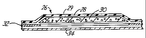
shown in Figure 3 where a patch 26 is illustrated in
generally a rectangular configuration. An exploded
section of the patch 26 is shown in Figure 4, except
that in Figure 3 the release paper is shown removed to
provide a view of a foam layer 30 around which the
adhesive layer 32 extends. The sectional views are
CA 02335066 2000-12-13
WO 99/65434 PCT/US99/13384
-12-
shown exploded, for illustration but the layers are
bonded together in use.
The patch 26 comprises a film or layer 28 of
the low friction material, such as PTFE, bonded to a
plastic foam layer 30 that is of smaller size than the
PTFE film layer. The foam 30 is shown in Figure 4 to be
substantially thicker than the PTFE film layer, but it
can be any thickness desired. The pressure sensitive
adhesive layer 32 is then applied, and can be provided
only on the peripheral edges as shown in Figure 3, to
provide an open center where the foam layer 30 would be
exposed for contact with the skin. A release paper
layer 34 overlies the bottom of the patch. The exterior
surface 29 of the PTFE film layer 28 provides the low
friction surface for reducing shear and tangential
traction against a support surface or material. The
foam layer 30 may' be in contact with the skin or the
surface of the support to provide cushioning and
protection. The foam layer 30 could be, for example, in
the range of a quarter inch thick, but would have
tapered or skived edges as shown so that the PTFE film
layer 28 would conform well to the foam. The adhesive
used is selected to bond to the PTFE layer so there is
an adhesive edge for adhering the patch on the skin or
other surface. The adhesive is a pressure sensitive
adhesive.
The preformed patch 26 shown in Figure 3 can
be sized to be 2, 3, or 4 inches long, for example, with
widths of 1, 1/2 and 2 inches. The patch 26 thus can be
used for any application where a spot or region of skin
is subject to shear and abrasion, so the tissue is
becoming tender, to relieve the tangential traction on
that portion of the skin.
CA 02335066 2000-12-13
WO 99/65434 PCT/US99/13384
-13-
Figure 5 illustrates an exploded cross section
of a modified patch 36 having the periphery shown in
Figure 3. The patch 36 has a PTFE film layer 38. The
PTFE film layer 38 is bonded to a stretch fabric layer
40 such as stretch nylon or Lycra. A foam layer 42 is
bonded to the fabric layer 40 in the center portions of
the patch. The pressure sensitive adhesive layer 44 is
placed on the surface of the fabric layer opposite from
the low friction outer surface 39 of PTFE film layer 38.
The adhesive layer 44 again can be formed as shown in
Figure 3 with a rim of adhesive surrounding an open
center where the foam layer 42 is exposed. A release
paper 46 is also provided on the patch as shown in cross
section. As stated, the PTFE films can be perforated as
desired.
The use of the stretch fabric 40 provides an
additional layer of cushioning and protection, which can
be stretched along with the PTFE film to fit rounded
surfaces or irregularities. The foam layer 42 has its
edges beveled, and the stretch fabric layer 40 and the
PTFE film layer 38 will fit closely around the foam.
The stretch fabric layer 40 is bonded to the PTFE film
layer 38 before placing the foam in position, so both
the fabric and the PTFE would be stretched at the same
time. This bonding, again, is done commercially by
Chemfab Corporation of Merrimack, New Hampshire, USA.
The PTFE film also can be bonded to leather and other
fabrics by ChemFab Corporation.
Peripheral dimensions of the patches for the
construction shown in Figure 5 can be the same as those
shown in connection with Figure 3, and the bottom view
would be the same as well. Of course other
configurations such as elliptical shapes and the like
can be used. The pressure sensitive adhesive layer 44
CA 02335066 2000-12-13
WO 99/65434 PCT/US99/13384
-14-
can extend all the way across the foam, so there is no
open center, if desired.
In Figures 6 and 7 a modified form of the
invention is shown, which has low coefficient of
friction film on both surfaces of the patch, so when the
patch that is shown in Figure 7 is placed on a corn or
callus, the surface in contact with the skin has the low
coefficient of friction and the outwardly facing surface
does also. The patch 50, as shown is elliptically
shaped, and in Figure 7 a cross sectional exploded view
is illustrated. A PTFE film layer having a low
coefficient of friction outer surface 53 is bonded to a
stretch fabric layer 54 and then a foam layer 56 that
has a hole 57 through the center is provided in the
center portions of the patch 50. In this form of the
invention, a layer 60 of PTFE film that is relatively
small in size is positioned in the hole 57 in the foam
and is bonded to the fabric layer for example with
pressure sensitive adhesive. A pressure sensitive
adhesive layer 58 is then bonded to the stretch fabric
layer 54 and the underside of the foam layer 56 but
surrounding the hole 57. A release paper layer 59
overlies the bottom surface of patch 50 and over the
adhesive. The layer of PTFE film 60 is shown in both
Figures 6 and 7, and has an outwardly facing low
coefficient of friction surface 61 that will reduce any
abrasion of skin that it contacts.
The foam layer 56 has a generally elliptically
shaped periphery as shown in dotted lines in Figure 6,
and the overall configuration then would be a patch 50
that could be adhered to skin, to provide a low friction
material directly against the skin with the small layer
of film 60, and a larger area of low friction film
CA 02335066 2000-12-13
WO 99/65434 PCT/US99/13384
-15-
defined by layer 52 that could engage the lining of a
shoe or the inner surface of a sock or the like.
Figures 8 and 9 illustrate a further modified
form of the invention comprising an elliptically shaped
piece or patch 66 that is made of a layer 68 of PTFE
film having an outer low coefficient of friction surface
69. Layer 68 is bonded to a stretch fabric layer 70.
A second layer of PTFE film 72, is smaller in size than
the top PTFE film layer 68 and the stretch fabric 70 and
is bonded to the stretch fabric 70 in the center
portions of the patch on an opposite side of the fabric
from the PTFE film layer 68. This can be seen in Figure
8.
A layer of pressure sensitive adhesive 74 is
then applied to the peripheral rim area surrounding the
film layer 72, and will provide for an adhesive layer of
sufficient size to permit adhering the patch 70 to the
skin, or objects or supports for the skin. A release
paper layer 75 is provided. This patch is made without
any cushioning or foam layer. The smaller center layer
72 of PTFE film does not have any adhesive between it
and the skin, so this is not adhered to the skin, but
has a low friction surface 73 that is free to slide
against the skin. This reduces the friction on the load
carrying surfaces significantly, and reduces trauma frott-
shear, even when it is of low magnitude. Low magnitude
shear can cause tissue damage if it cycles repeatedly.
Figure 10 illustrates schematically a foot
within a shoe drawn in phantom to illustrate in cross
section, regions where high load and/or rubbing areas
can benefit from the application of the low friction
patches made according to the present invention. In
Figure 10, the bones of the foot are illustrated at 80,
and they are shown within the outline of a shoe 82.
CA 02335066 2000-12-13
WO 99/65434 PCT/US99/13384
-16-
High load bearing areas of course are located -under the
metatarsal heads 84, the heel or calcaneus 90, and the
end of the toes, in particular the big toe 97. The
metatarsal heads 84 are supported on a patch 86. This
patch 86 can be on top of the insole 87 and thus between
the sock (and foot) and the support provided by shoe 82.
The patch 86 can be installed in the shoe 82
permanently, by sewing if desired. Patch 86 provides a
low friction surface area where the sock can slide
easily relative to the surface of the patch 86 and will
not tend to abrade against the skin of the foot in the
high load support area.
The patch or pad 86 can extend across the
width of the metatarsals, so that the entire metatarsal
head region (the metatarsal-phalangeal joint region) of
the foot is supported on a relatively low friction
surface. The patch or pad 86 preferably has an outer
PTFE film layer, backed by a stretch fabric and held in
place on the shoe insole. A foam layer as shown in
Figure 5 can be provided in the patch or pad 86, if
desired.
Another region that can be supported is at the
toe end surfaces, in particular the big toe, such as
that shown with a pad 88 under end of the big toe 97.
This is a region that is not subjected to extremely high
loads, but there is a lot of cyclic loading, including
shearing, as one moves. The toe supports forces as the
person pushes off on each stride, particularly when
running.
The heel bone or calcaneus indicated at 90 has
a bony prominence 92, that is supported on a patch 94
having a low coefficient of friction outer surface
region. The patch or pad 94 will provide support and
reduce any shear loads if there is slippage during the
CA 02335066 2000-12-13
WO 99/65434 PCT/US99/13384
-17-
stride. Additionally, the cushioning patches-that are
shown, having a foam layer can provide some cushioning
support and conformability around protrusions in the
heel bone to reduce trauma and damage.
A non-load-bearing area where cyclic shear
loads can cause damage is shown above a toe where a
joint may be deformed or contracted so the bone is
raised up as shown at 96 and will tend to rub against an
upper surface of the toe box 98 of the shoe 82. The
installation of a pad 100 directly on the toe, or on the
interior of the shoe on the top interior surface of the
toe box will reduce the shear loading to a point where
even cyclical loading will not cause shear damage,
blistering, callusing or the like. In a nonweight-
bearing area, therefore, the low friction surface
patches also provide relief. Bonding PTFE film to
leather permits lining the toe box of a shoe to reduce
friction in the entire toe region.
The patches or pads of the present invention
find needed application in ankle-foot orthoses. One
such orthosis is shown in Figure 11, at 104 and includes
a foot support shell 106, and ankle and leg support
shell 108 joined together with flexure members 110 in a
conventional manner so that the foot shell 106 can be
flexed relative to the leg support. The shells are open
in the front and top, as can be seen, and a retaining
strap 112 is used for retaining the leg in position.
Additional securing devices can be used for the foot.
The interior surfaces of the shells 106 and
108 support the foot, the ankle, and the lower leg
snugly, but there can be some sliding or shear forces
generated. A patch 114 that is relatively large and
which can be cut from the form of the invention shown in
Figure 1, is positioned in the longitudinal arch area.
CA 02335066 2000-12-13
WO 99/65434 PCT/US99/13384
-18-
Suitable foams can be used between the shell surface and
the pad, a low friction material PTFE is provided on the
top surface of the patch that engages the underside of
a foot in the orthosis, through a sock, in this high
load support area. The pad or patch 114 can be
configured to provide support in the arch area as well
as reducing the friction loads that occur from any
sliding, particularly under high forces. The patch 114
can be made as shown before with foam underneath the
PTFE film layer. Use of a stretch fabric layer backing
the PTFE film is desired because of some irregular
contours that have to be followed on the formed foot
shell 106.
The low friction surface pads used where there
is flexing, insures that the shear loads are very low,
and have the advantage of having foam attached or bonded
to the film surface. Conventional foam pads are very
high friction and will tend to cause tissue damage from
repeated shear loads even though direct weight support
is not present. Additionally, a medial leg support
patch or pad shown at 120 can be provided above the
ankle bone, and this includes foam padding behind a PTFE
film layer for increasing or modifying the pressure
distribution and provide increased corrective forces.
The pad 120 can be again cut to the desired shape, and suitable foams can be
used under the PTFE layer. Here,
too, the pad preferably has the bonded stretch fabric
beneath the outer PTFE film layer because of the need of
conforming to irregular contours.
The edges of the shell can be lined with the
low friction surface patches or pads 122 to reduce shear
in these regions. The patches or pads can be folded
over the edges and adhered in place. The main portion of
CA 02335066 2000-12-13
WO 99/65434 PCT/US99/13384
-19-
the pads on the edges should be on the 'interior
surfaces.
Figure 12 illustrates a typical foot and lower
ankle joint, and the region shown at 114A, where the pad
or patch 114 would bear on the arch. The upper pad or
patch region on the leg is shown at 120A..
Figure 13 is a top view of a typical
transtibial prosthetic leg 123. The prosthetic leg 123
includes a rigid socket 124 and a soft socket liner 125
which will receive a residual limb, and support the
residual leg at and just below the knee. In such a
prosthesis, there are regions where tissue is thin over
bony prominences, such as at the lateral, anterior and
bony prominences near the top of the tibia and the tibia
crest. These regions are also shown in Figure 13, and
pads shown at 126 and 128 for bony prominences are
placed appropriately in the socket liner 125. The
socket has a rigid shell 124 that normally has a liner
125 made of a suitable material such as a foam or gel.
The patches according to the present invention provide
for low friction support between a covering sock or
layer of material and the supporting surface. In Figure
14, the tibial crests, the medial and lateral bony
prominences near the top of the tibia are indicated at
130A, 126A, and 128A. The patches or pads can have foam
underneath the low friction film layer. The low
friction surfaces reduce shear loading against the skin
and subcutaneous tissue when the skeleton moves relative
to the socket. The outer shell 124 supports a lower leg
portion of the prosthesis.
Additionally, the tibial crest pad 130 of
Figure 13 is aligned with the tibial crest shown at 130A
in Figure 14. The pad 130 has the PTFE film outer layer
bonded to a stretch fabric because of irregular contours
CA 02335066 2000-12-13
WO 99/65434 PCTlUS99/13384
-20-
that have to be followed on the socket. Suitable foam
padding can be provided to insure some load distribution and conformability
onto the tibial crest.
Another bony area of support for a lower leg
prosthesis is the fibular head shown at 132A in Figure
14. A fibular head pad 132 (Figure 13) is placed to
cushion the lateral side of the remaining limb and
around the rear of the leg. The head of the fibula bone
is quite close to the skin surface in these locations,
so that very high pressure and shear.loads are carried
in this region and damage can easily occur. The patches
of the present invention reduce the friction between the
limb and the supporting surfaces of the socket, to
provide for a smooth surface that is very low friction
so that the tissue is not subjected to shear loading.
The upper edges of the socket 124 can be lined with
patches, if desired.
Figure 15 is a view of a socket used for a
full leg prosthesis (trans-femoral amputation), where
support is provided at the femur and pelvic bones. The
shell shown at 140 has an upper socket region 142, and
the lower portion 143 that supports a knee joint, pylon
144 and a foot prosthesis 146.
In this instance, a large patch or pad 150
made according to the present invention can be provided
in the frontal area where loads will be directly applied
to relatively soft tissue, and this will reduce
frictional loads as soft tissue tends to move, for
example, the residual limb tends to move in and out as
the upper leg flexes between sitting and standing
positions. The reduction in frictional loads is achieved by having the PTFE
film layer on the exterior
and the patch or pad adhered to the socket so that it
CA 02335066 2000-12-13
WO 99/65434 PCT/US99/13384
-21-
does not slide on the socket. Friction loads on the
remaining limb portion is greatly reduced.
Also the patch or pad 152 avoids shear as
weight is applied to the socket, which causes relative
shifting of the limb and shell.
Additionally, an irregularly shaped patch or
pad 152 is provided along a rear rim or edge portion of
the socket, where relatively high loads are encountered.
This pad or patch 152 can be provided with the stretch
fabric layer bonded to PTFE film for conformability. A
foam layer can underlie the stretch fabric. The layer
of PTFE on the exterior reduces friction in the high
load contact area between the socket support regions and
the remaining limb and pelvic bones. Other regions, can
also be covered with the pads of the present invention
to provide a low friction interface between the
remaining limb and the socket. Foam layers can be used
where needed.
A series of tests were conducted between the
available products on the market for corn pads, liners,
and the like, used in shoes and other regions where
support relative to the skin is desired, as well as
other materials, such as adhesive bandages. The
following Tables 1, 2 and 3 show average coefficient of
friction values and standard deviations for dry and wet
interface tests. Nine trials were performed for each
test in measuring coefficient of friction, and the
results averaged.
In the tests a sled surface was covered with
the sock material and moved across the test material
while the incline angle measurements were made.
CA 02335066 2000-12-13
WO 99/65434 PCT/US99/13384
-22-
TABLE 1
SURFACE MATERIAL DRY TEST WET TEST
SOFT MATERIALS Ave St Dev Ave St Dev
BockLite 1/811 0.49 0.10 0.56 0.03
Orthopedic Cowhide 0.49 0.11 0.68 0.03
PPT with Ultrilure 0.57 0.07 0.57 0.02
Top Coverup
IPOCONO Gel with 0.41 0.08 0.48 0.02
Lycra Top Coverup
Moleskin J&J 0.63 0.03 0.87 0.03
PE Lite 1/16" 0.51 0.08 0.48 0.02
Plastazote .125" .57 0.06 0.51 0.05
Diab-A-Sheet - PPT 0.55 0.09 0.67 0.03
side up, plastazote
down -
Russett Cow Leather 0.41 0.15 0.62 0.06
PRESENT INVENTION
Pad of Figure 4 0.16 0.02 0.16 0.02
Pad of Figure 2 0.16 0.02 0.17 0.02
CA 02335066 2000-12-13
WO 99/65434 PCT/US99/13384
-23-
TABLE 2
SURFACE MATERIAL DRY TEST WET TEST
BANDAGES Ave St Dev Ave St Dev
Band=AidO Clear 0.47 0.01 0.53 0.01
From J & J
Band-Aidp Large 0.46 0.04 0.53 0.03
From J & J
Band-AidO Plastic 0.45 0.02 0.51 0.03
From J & J
Blister-Care 0.78 0.01 0.76 0.07
From CuradO
Clean Seals 0.64 0.02 0.57 0.02
From 3M
Duoderm CGF 0.38 0.03 0.30 0.01
From Convatec
Nexcare Active 1.01 0.02 0.61 0.01
Strips' _
From 3M
Sheer Bandages 0.59 0.04 0.58 0.04
From Walgreens
PRESENT INVENTION
Pad of Figure 4 0.16 0.02 0.16 0.02
Pad of Figure 2 0.16 0.02 0.17 0.02
CA 02335066 2000-12-13
WO 99/65434 PCT/US99/13384
-24-
TABLE 3
SURFACE MATERIAL DRY TEST WET TEST
PLASTICS Ave St Dev Ave St Dev
Orthoplast 0.29 0.02 0.46 0.09
Modified 0.28 0.03 0.30 0.03
Polyethylene
CO Polyester 0.27 0.04 0.41 0.01
Polypropylene 0.23 0.02 0.34 0.05
PRESENT INVENTION
Pad of Figure 4 0.16 0.02 0.16 0.02
Pad of Figure 2 0.16 0.02 0.17 0.02
In Table 1 above, Bocklite is a product
manufactured by Otto Bock Othopedic, Inc. Of
Minneapolis, Minnesota; Orthopedic Cowhide and Russett
Cowhide leather are available from Roden Leather of
Royal Oaks Michigan; Diab-A-Sheet, a composite sheet of
Plastazote and PPT foam layers and PPT with Ultrilure
top cover are both available from The Langer
Biomechanics Group Inc of Deer Park, New York; IPOCONI~)
gel with Lycra top cover is sold by IPOS Orthopedics
Industry, Niagara Falls New York; Moleskin is an
adhesive bandage sold by J.N. Johnson Sales of'
Minneapolis, Minnesota; PE Lite and Plastazote (a
polyethylene foam) are sold by Pel Supply Company of
Cleveland, Ohio.
In Table 2, all Band-Aid products and
Orthoplast are made by Johnson & Johnson Consumer
Product, Inc. of Skiliman, New Jersey; Clean Seals and
Nexcare''o Active Stripsm are from 3M Health Care of St.
Paul, Minnesota; Blister-Care is distributed by A
Beiersdorf Co. of Milford, Ohio; Duoderm CGF is
CA 02335066 2000-12-13
WO 99/65434 PCT/US99/13384
-25-
distributed by the ConvaTec Division of E.R.- Squibb &
Sons, Inc. of Montreal, Quebec, Canada; Sheer bandages
are from Walgreens Co. of Deerfield, Illinois.
In Table 3, modified Polyethylene and Co-
Polyester are distributed by American Plastics of Ft.
Worth, Texas; and the Polypropylene is from Seelye
Plastics, Inc. of Bloomington, Minnesota.
It can be seen that the pads of the present
invention maintain lower friction characteristics
whether the cotton socks used were wet or dry. For
testing the "wet" socks were saturated with steam at
150 F. Some of the material such as BockLite did not
vary substantially between wet and dry conditions (high
friction in both cases) , but other commonly used natural
liners such as orthopedic cowhide, moleskin, russett
leather, and the like increased in coefficient of
friction substantially in the presence of moisture. The
presence of moisture is common where perspiration will
cause socks to become damp.
Studies in relation to the causation of ulcers
on the skin indicate that when there is a relatively
high level of shear, the pressure necessary to produce
blood flow occlusion is reduced substantially from when
little shear is present. This means that providing low
friction surface patches in critical areas, where shear
forces can be generated will tend to reduce the
likelihood of formations of ulcers or calluses.
In bony areas, such as the lower leg area,
shear displacements from pistoning motions result in
higher shear strains where the tissue is thinnest, the
shear strain is a function of the tissue thickness to
the bony support. Thus, at the front edge of the leg,
a similar shear displacement of the outer skin results
in a higher shear strain than at the rear or fleshy part
CA 02335066 2000-12-13
WO 99/65434 PCT/US99/13384
-26-
of the leg. Shear strain is a function of the shear
displacement divided by the thickness of tissue between
the surface of the skin and the bony support.
Thus, the present invention relates to the use
of a very low friction film under both dry and moist
conditions, having a support surface that substantially
reduces the coefficient of friction that is active to
cause shear loads.on skin supported on that particular
film, whether through a sock, a cloth material of some
kind, or directly against the skin. In so doing, the
likelihood of ulceration, calluses, or similar problems
caused by shear strains and stresses is reduced. The
size and shape of the pads can be custom made as
desired, the pads can be used with or without foam
cushioning. The pressure sensitive adhesive used is a
convenient way of applying pads in regions where
temporary relief may be made, but the film can be also
permanently stitched into the interfaces of a shoe or
boot, or of a prosthetic device, such as a prosthetic
limb. Installation of pads in orthoses is also very
convenient. Treatment can be carried out for spots that
seem to be developing sores or which become tender, by
placing a low friction patch between the load bearing
area of the body or skin and the object that is applying
the load so that shear is reduced in that localized area. Thus, the method of
treatment includes adding
suitable sized patches in regions between tender or sole
areas of the skin and the shoe or support object.
Although the present invention has been
described with reference to preferred embodiments,
workers skilled in the art will recognize that changes
may be made in form and detail without departing from
the spirit and scope of the invention.