Note : Les descriptions sont présentées dans la langue officielle dans laquelle elles ont été soumises.
CA 02335118 2000-12-14
WO 99/66138 PCT/CA98/00591
Title: SEILF-CLEANING HAND WASHER
FIELD OF THE INVENTION
The invention relates to hand washing machines and, in
particular, to a self-contained hand washing machine which may be
self-cleaning between each usage.
BACKGROUND OF THE INVENTION
Washing of the hands is believed to be one of the first
safeguards against spreading infection, whether in a health care
institution, or in any other facility or location. However, the facilities
which are usually provided for hand washing are to say the least
somewhat primitive, and have scarcely changed in design since
plumbing was first introduced. Most hand washing facilities are based
on a basin, with hot and cold water taps, and a source of soap. Drying
of the hands is at besi: dependent on disposable paper towels, or in
many cases by hot air hand dryers.
Disposable paper towels frequently do not get rid of all of
the residue from washing. Disposal of the towels may result in
recontamination of the hands. Hot air drying of the hands uses small
appliances with fans and electrical heating coils. These appliance
when brand new work reasonably well, simply blowing fresh air over
the hands. However, after even a small amount of usage
contaminated air is drawn into the hand dryer and bacteria may
accumulate in the wann, moist atmosphere of the dryer. The result is
that from then on the hands are dried in air which may be carrying a
substantial volume of bacteria.
Even the rnultiple washing of the hands many times does
not overcome these problems.
A further problem is that the sink or basin in which the
washing water is collected itself becomes a source of contamination
after only a very few usages. Dirt and dried soap collect, and breed
bacteria in the basin itself.
CA 02335118 2000-12-14
WO 99/6613$ PCT/CA98/00591
-2-
The operation of the handles on the faucets is itself yet
another source of contamination. Persons may turn the faucets on
and off, for example, after relieving themselves, when their hands are
actually contaminated, and thereby leaving contamination on the
handles of the faucets. For all of these reasons, therefore, the use of
conventional hand washing facilities, even those in health care
institutions, is unsatisfactory and unhygienic and may actually result
in the spreading of infection and bacteria, rather than the reverse.
BRIEF SUMMARY OF THE INVENTION
According to the instant invention, there is provided a
hand washing apparatus comprising a hand washing bowl and a cover,
the bowl and cove:r being reconfigurable between a hand washing
position and an inactive position in which the bowl is closed by the
cover; a controller for reconfiguring the bowl between the hand
washing position and the inactive position; and, a dispenser for
dispensing water, a cleaner and rinse water over hands in the bowl.
In an alternate embodiment, the hand washing apparatus
comprises a hand 'washing bowl mounted at a suitable height for
washing hands; a controller for opening the bowl into a hand washing
position and closing; the bowl into an inactive position; a warm water
dispenser for disperising warm water over hands in the bowl; a soap
dispenser for dispensing soap over hands in the bowl; and, a rinse
water dispenser for dispensing rinse water over hands in the bowl.
In a further alternate embodiment, the hand washing
apparatus comprises a hand washing bowl and a cover, the bowl and
cover being reconfigurable between a hand washing position and an
inactive position in -which the bowl is closed by the cover; a dispenser
for dispensing water, a cleaner and rinse water over hands in the bowl;
and, a controller ac:tuated without use of the hands of the user for
CA 02335118 2000-12-14
WO 99/66138 PCT/CA98/00591
-3-
actuating the reconfiguration of the bowl and the cover between the
hand washing posit:ion and the inactive position.
The bovvl may be mounted at a suitable height for washing
hands and is mounted for rotation about a generally horizontal axis
between the hand washing position and the inactive position. The
bowl may be of a generally hemispherical shape and when the bowl is
in the hand washing position, the bowl is open upwardly for access by
a user and when in the inactive position, the interior of the bowl is
inaccessible by a useir.
The hand washing apparatus may include an air dryer for
generating a stream of hot air flowing over the hands of a user, the air
dryer being operable by the user without touching the apparatus.
Preferably, the air di.yer is automatically operable after completion of a
washing cycle. The hot air may be disinfected prior to flowing over the
hands of a user.
The hand washing apparatus may include a discharger for
discharging a disinfectant into the bowl when the bowl is in its
inactive position, for flowing around the interior of the bowl and
rendering the same clean. Further, an air stream may be provided to
dry the bowl after the bowl has been cleaned.
A collection sink may be positioned to receive the liquid
contents of the bowl when the bowl is in the inactive position.
The harLd washing apparatus may include a sensor for
recognizing a particular user prior to the activation of a washing cycle.
The apparatus may have a controller that is preprogrammed with at
least two different washing cycles, the user selects the desired washing
cycle, and the apparatus includes a recording media to record the cycle
that was selected by the particular user.
The apparatus may have a controller that is
preprogrammed with at least two different washing cycles and the user
selects the desired washing cycle.
CA 02335118 2000-12-14
WO 99/66138 PCT/CA98/00591
-4-
The haind washing apparatus may also have a sensor for
recognizing a particular user prior to the activation of a washing cycle,
wherein the recognition of a particular user actuates the controller.
The hand washing apparatus may also have a foot pedal to
actuate the controller.
According to the instant invention, there is also provided
a method for a person to wash their hands using a hand washing
apparatus comprising a hand washing bowl and a cover which are
reconfigurable between a hand washing position and an inactive
position, a controller for reconfiguring the bowl between the hand
washing position <ind the inactive position; and, a dispenser for
dispensing water and a cleaner over the user's hands, the method
comprising the steps of actuating the controller to move the bowl and
the cover to the hand washing position; dispensing water and soap
over the user's hands; and, dispensing water to rinse the user's hands.
The method may also include dispensing a stream of hot
air over the hands of a user.
The method may also include dispensing a disinfectant
into the bowl wherL the bowl is in its inactive position, for flowing
around the interior of the bowl and rendering the same clean. Further,
the method may include dispensing an air stream to dry the bowl after
the bowl has been cleaned.
The apparatus may also have a controller that is
preprogrammed with at least two different washing cycles and the
method may include selecting the desired washing cycle whereupon
the various fluids are thereafter automatically dispensed.
The apparatus may also have a sensor for recognizing a
particular user and the method may further comprise the step of using
a card to identify the user to the apparatus prior to the activation of a
washing cycle. Further, the user may present an identity card to the
sensor to activate the apparatus.
- ------- ----- - - --------- --
CA 02335118 2000-12-14
WO 99/66138 PCT/CA98/00591
-5-
One advantage of the instant invention is that it provides
a hand washing facility in which the hands of the user need not touch
the basin, taps or soap dispenser. The water may be mixed to the
correct temperature automatically so that the taps do not have be
manually operated. Accordingly, the cycle of operations may be
controlled by automatic controls and timers so that no input is
required from the user.
A further advantage of the instant invention is that in the
inactive position of the bowl, the bowl is inaccessible so as to avoid
collection of contamination. Thus, the entire apparatus is self-
contained within a closed housing for security and cleanliness and
requiring only regular maintenance by qualified trained personnel.
Further,, the soap or other cleaning or rinsing composition
is preferably dispensed automatically so it does not accumulate or
substantially accumulate as a residue, and the basin is preferably rinsed
and dried after each use so that the bowl is cleaned after each use to
prevent bacteria from growing therein.
In some cases, hand drying aids such as towels can be
provided for use in conjunction with the warm air drier.
The entire washer may be of such a compact unitary
design that it can be installed almost anywhere, not merely in
bathrooms. In this way, more frequent washing of the hands is
encouraged, and the unit will maintain a clean, attractive appearance
without daily maintenance.
IN THE DRAWINGS
The various features of novelty which characterize the
invention are pointed out with more particularity in the claims
annexed to and forming a part of this disclosure. For a better
understanding of th.e invention, its operating advantages and specific
objects attained by its use, reference should be had to the
CA 02335118 2000-12-14
WO 99/66138 PCT/CA98/00591
-6-
accompanying drawings and descriptive matter in which there are
illustrated and described preferred embodiments of the invention in
which:
Figure 1 is a front elevational view of the hand washing
machine in accordance with a preferred embodiment of the invention,
with the front removed so as to show various parts of the interior;
Figure 2 is a side elevational view partly in section
showing the machir.ie in the liand washing position;
Figure 3 is an enlarged sectional view corresponding to
Figure 2 showing the basin portion rotated inwardly for rinsing and
disinfection;
Figure 9: is an enlarged front elevation of the bowl, rotated
to its hand washing position;
Figure 5 is a plumbing diagram showing the water inflow
and outflow routing; and,
Figure Ei is an electrical block diagram showing the basic
controls, and their relation to a foot switch.
DESCRIPTION OF THE PREFERRED EMBODIMENT
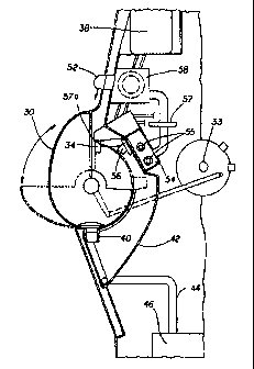
Figures 1 and 2 illustrate a hand washer demonstrating
the various features of the invention, and comprising a generally
rectangular upright housing 10 having sidewalls 12, 12 and a back wall
14. A contoured front wall 16 defines a roof 18, and forwardly
projecting washing iregion 20. A recessed foot region 22 is defined at
the lower end of front wall 16.
Within the front wall 16, on suitable framework, the
details of which are omitted for the sake of clarity, there is a hand
washing bowl indicated generally as 30. Bowl 30 is reconfigurable
between an open configuration in which the bowl is configured for a
user to wash their h.ands and a closed configuration in which bowl 30
may be cleaned afteir use. Preferably, bowl 30 is moveable between an
CA 02335118 2000-12-14
WO 99/66138 PCT/CA98/00591
- 7 -
open position in which the bowl is positioned for a user to wash their
hands and a closed position in which bowl 30 may be cleaned after use.
Alternately, the bowl 30 could be stationary and have a cover which
moves to cover or uncover the bowl.
Bowl '30 may be moved between the open and closed
positions by any rneans known in the art. Preferably, bowl 30 is
pivotally mounted along a generally horizontal pivot axis by means of
bearings 32. In this way, the bowl or sink 30 can be rotated to open
outwardly for washing (Figure 2) and rearwardly into a covered
inactive position for rinsing and disinfecting (Figure 3) by suitable
motor and crank r.neans 33. While the bowl is described as being
rotatably mounted, other forms of moveable mounting are possible.
Thus, the bowl could simply slide in and out. Preferably, bowl 30 is
mounted so that, when it is in the hand washing position, it is
mounted at a suitable height for a user to wash their hands.
It will be appreciated by those skilled in the art that bowl
30 may be of any particular shape and that the actual shape of bowl 30
may vary depending upon whether bowl 30 is movably mounted and,
if so, how it moves. For example, if bowl 30 is pivotally mounted, then
bowl 30 is preferably of a generally semi-spherical shape. Thus, when
rotated rearwardly to the closed position (Figure 3), the underside of
30a of the bowl presents a. smooth generally convex appearance,
effectively closing and sealing the interior of the entire apparatus and
preventing contamination by garbage or debris or personal
contamination. Alternately, if bowl 30 is slideably mounted so as to
slide in and out, then bowl 30 may be cylindrical in cross section.
Locatecl to one side of the bowl, within the interior
enclosed by front vrall 16, is a water outlet indicated generally as 34.
Nozzle 34 is positioned to direct water, preferably at a median
temperature suitable for hand washing, into bowl 30 for wetting of the
hand. Water may be supplied to nozzle 34 by a pump (not shown), or
CA 02335118 2000-12-14
WO 99/66138 PCT/CA98/00591
-8-
simply by using the main's water pressure through a pressure
regulator.
A cleaner, e.g. soap, is supplied for washing. The cleaner
may be dispensed by passing the water through a suitable
water/cleaner mixing valve 36 upstream from nozzle 34. Accordingly,
valve 36 may be connected to a supply of cold water via conduit 36a
and connected to a water heater 37 contained within the apparatus via
conduit 36b, and controllable so as to supply a warm water mix at an
appropriate temperature for washing hands. Pursuant to this
embodiment, there is provided a container 38 for storing a cleaner for
use when a user washes or rinses their hands. A plurality of such
containers may be provided, each of which may contain a different
cleaning compound. For example, as shown in Figure 1, a soap
container 38 and a disinfectant liquid material tank 39 are connected to
the nozzle 34. The container or containers may thus supply a soap,
disinfectant or the like to the valve 36 for mixing with the water
preferably at an appropriate concentration of cleaner to water.
In alterr-ate embodiment, if the cold water supply is at a
suitable temperature, then hot water heater 37 will not be required.
Instead, the cold water supply may be fed directly to mixing valve 36
without combining the cold water with any heated water. This
approach may also be used if a hot water supply and a cold water
supply are first corutected to a mixing valve and the mixing valve is
then connected to the inlet water port for housing 10 (not shown).
Alternately, the cleaner may be dispensed by a dispenser
directly onto the hands of the user without the user using their hands
to operate the dispenser. For example, the dispenser could be actuated
by an optical senso:r or by a remote actuator, eg. a foot pedal (not
shown). According; to this embodiment, the user may place their
hands below the dispenser at which time the optical sensor will sense
the presence of the user's hand thereunder and dispense an aliquot of
CA 02335118 2000-12-14
WO 99/66138 PCT/CA98/00591
-9-
cleaner or at which time the user may actuate the foot pedal. A
plurality of dispensers, each with an associated actuator, may be
provided.
If bowl 30 is rotatably mounted, it preferably has a
rearwardly directed drain spout 40, for discharge of its contents, when
it is rotated rearwardly. If bowl 30 is slideably or fixedly mounted, then
spout 40 may be positioned at the lowest point of bowl 30 when bowl
30 is in use.
In order to catch the wash water, residue and any
disinfectant from bowl 30, bowl 30 may be in turn preferably mounted
over a sink 42, which is fixed within the interior of front wall 16, and
is connected by a conventional plumbing waste pipe 44 to a sump 46.
In this way, when bowl 30 is :rotated rearwardly, it will dump all of its
contents through spout 40 into sink 42 and down the waste pipe 44. It
will be appreciated that if bowl 30 is not rotatably mounted, it may be
directly connected to waste pipe 44.
The waiter mixer, soap container 38 and disinfectant
container 39 and their pumps 38a, 39a may be connected through a
suitable timing mechanism (e.g. controller 70) so as to provide a timed
operation for washing, for example, an initially wetting of the hand,
followed by a soaping of the hands, followed by a rinsing of the hands
in warm rinse water. At the end of the cycle, the washer may be
automatically reconfigured to the closed position, such as by bowl 30
rotating rearwardly. It will be appreciated that alternate washing cycles
may be preprogramrned. The user may select a desired cycle before use
by pushing a button or by tripping an optical sensor (not shown). The
different cycles may employ different chemical mixtures and/or may
use shorter or longe,r periods of washing and/or rinsing. For example,
there may be a quick rinse cycle when a full wash is not required. It
will also be appreciated that the wash cycle may be manually
-- ------------
CA 02335118 2000-12-14
WO 99/66138 PCT/CA98/00591
-10-
controlled. For example, by a series of foot pedals or a series of optical
sensors.
After ,,vashing, the washing bowl 30 is then preferably
cleaned by water sluch as cold water which is supplied to the mixing
valve 36 by the mains, receiving cold water from the conventional
cold water supply together with a disinfectant, for washing and
cleaning the bowl. Hot water could be used if desired. The washing
mixture will drain out of bowl 30 through spout 40 and into sink 42.
The bowl may then be dried by air being drawn from outside.
In the preferred embodiment, the apparatus is operable
without the user's hands contacting the apparatus once the washing
cycle commences. For example, the operation of the washer could be
actuated by a user pushing a start button or by a user inserting coins
into a coin fed actuator as are know in the vending machine industry
(not shown). More preferably, the entire cycle of the machine,
including the reconfiguration of bowl 30 and its cover, is actuated
without the user's hands touching any of the controls. For example,
the entire operation of bowl 30 and the water and soap dispenser may
be initiated by means of an actuator, such as a foot operated pedal 50
(Figure 2) or an optical sensor or a proximity sensor keyed to a securing
card (not shown) so that the user's hands do not touch any of the
controls after the washing cycle commences.
In order to dry the user's hands, a hot air dryer nozzle 52 is
preferably provided (Figure 1.). Hot air nozzle 52 may be provided to
supply heated and, preferably, heated and disinfected air. For this
purpose, an air disinfecting chamber 54 may be provided with, for
example, ultraviolet light tube 55. Air may be drawn inwardly
through nozzle 56 t;hen through a suitable filter 57 and heater and fan
58 before exiting at the nozzle 52. Preferably, nozzle 56 may also be
provided with filter 57a to prevent contaminants from entering, or
reduce the contaminants entering, nozzle 56. By providing filter 57a
CA 02335118 2000-12-14
WO 99/66138 PCT/CA98/00591
-11-
for nozzle 56, the surface of filter 57a may be positioned so as to be
exposed to the ultraviolet light emanating from ultraviolet light tube
55 thus helping to ;reduce the contamination of filter 57a. Nozzle 52
and a fan (not shovvn) are preferably timed (eg. by controller 70) to
supply sufficient hot air for the drying of the hands after rinsing. The
drying cycle may be controlled by an optical sensor as is known in the
art. In this way, not only are the hands thoroughly cleaned and
washed without cor-tact with any part of apparatus, but they are also
dried by disinfected air.
When bowl 30 rotates rearwardly, it may then be rinsed,
disinfected and dried. To this end, the air which is drawn through
nozzle 56 may first be drawn around bowl 30 rendering it dry and clean
for the next user. If desired, this drying air could also be disinfected
and/or heated. Alte:rnately, air from hot air nozzle 52 may be used to
dry bowl 30.
From time to time, it may be desirable for service
personnel to wash down the entire unit. For this purpose, a flexible
hose 60 may be provided. Flexible hose 60 preferably has a manually
operable jet nozzle 62 and is connected to the water supply within the
apparatus such as through a suitable valve 64 designed to be operable
only by the service personnel so as to prevent vandalism and abuse.
As shovvn in Figure 1, the device preferably includes a
safety feature, namelly optical sensor 66, which senses the presence of a
person's hands in the vicinity of bowl 30 when it is open. This optical
sensor prevents reverse rotation of bowl 30 so long as the person's
hand are still in the vicinity of bowl 30, thereby preventing a possible
injury. It may also include a light to illuminate the hands so that a
person can check for cleanliness.
It will, of course, be appreciated that there are a large
number of detailed electrical connections and controls and valves and
relays. Reference to the plumbing diagram Figure 5 and block diagram
CA 02335118 2000-12-14
WO 99/66138 PCT/CA98/00591
-12-
Figure 6 will clarify the operation of the apparatus, and be a sufficient
explanation for persons skilled in the art to understand the design and
construction of the apparatus.
As shoivn in Figure 6, a main controller 70, which may be
operated by, e.g., foot switch 50, may be connected to a use counter 72, a
rinse switch 74 and a hand wash solenoid 76. It may also be connected
to two pumps 78 arLd 80 and to a bowl operation protection device 66
already referred to and the ultraviolet light tube 55, and to the dryer
operation 54.
With the sump reservoir 46, a pump 48 is preferably
provided to periodically empty the sump. The reservoir can also be
connected to the main plumbing drainage if desired.
A status display 82 may be connected to the controller via
the protection circuit 84, so as to provide a visible display of the
operative status of tl'1e apparatus.
The operation of the whole apparatus is self-evident from
the foregoing description. In the preferred embodiment of the Figures,
in the storage position, bowl 30 is normally positioned rotated
rearwardly so that the hemispherical underside of the bowl is directed
outwardly, thereby rendering the entire apparatus secure, and sealed
all around the bowl. A user wishing to use the apparatus will first of
all operate the foot control, and a sequence of operations may then be
started as follows:
A. Bowl 30 rotates to the open position.
B. Clean water at the controlled temperature is
dispensed over the hands to wet the hands prior to the washing step.
C. A. cleansing solution of water and soap or other
disinfectant or cleaner is then mixed with the water and then
dispensed over the hands so that the hands may be washed.
CA 02335118 2000-12-14
WO 99/66138 PCT/CA98/00591
-:13-
D. A rinsing solution of water at the controlled
temperature is then dispensed over the hands so that the hand may be
rinsed clean.
E. The hands are then withdrawn from the bowl and
bowl 30 rotates closed, dumping the washing water into the sink 42,
where it flows under gravity to the sump tank. Prior to the withdrawal
of the hands from bowl 30, the bowl is prevented from closing
inadvertently by the safety light.
F. A, hot-air jet is then directed over the hands, having
been first of all passed through the ultraviolet chamber to disinfect the
air.
G. Water and a disinfectant mixture is then sprayed
around the interior of the bowl, while it is closed, to disinfect the
interior of the bowl, Air is drawn in around the bowl to dry it. This
may be the air drawn in to feed the hot-air jet. In some cases, this air
may be first disinfected and heated.
If desired, air, either hot or cold, can be directed around
the side areas of the front panel on the side of the bowl, the sink and
also around the flocir next to the foot pedal to dry any moisture that
may have escaped.
The counter 72 will record usage. In a more preferred
embodiment, the device may also include a sensor 86 so as to identify
the actual user. Tt-us counter 72 may identify the actual user, the
actual wash cycles activated by the user and the time when the user
used the washer. Sensor 86 may be any type which is known in the art.
For example, sensor,36 may be adapted to identify a user by the security
badge which the user might otherwise carry. For example, sensor 86
may be adapted to read a magnetic strip. Thus, in order to be able to
activate the unit, the user must first swipe their card through sensor 86
and then proceed as described above. Alternately, sensor 86 may be of
the proximity senso:r type so that by placing the security badge near
CA 02335118 2000-12-14
WO 99/66138 PCT/CA98/00591
-14-
sensor 86, it will identify the user, or it may include a bar code reader
to read a bar code afiEixed, for example, to a security badge.
After an appropriate count of uses, maintenance
personnel may then. check the apparatus, clean it and wash it down,
and refill the various containers.
The apparatus will be seen to provide both an effective
disinfected means of cleaning the hands, without the user's hands
contacting any contaminants once the washing cycle commences as the
cleaning water is operated automatically without manual control, the
soap dispenser is operated automatically without manual control and
the bowl itself may be cleansed and disinfected between each usage
after which the user's hands may be dried by disinfected hot air. The
whole operation as far as the user is concerned may be controlled by
means of a foot pedal or the like thereby removing further sources of
contamination comr.non to conventional hand cleaning facilities.
The controlling of a washing cycle is designed to meet the
various codes, such as FDA requirements. The invention preferably
controls the sequence of event, the timing and duration, temperatures,
the solution mixes, the cleaning of the bowl, the drying of the hands,
as well as recording the successful completion of this sequence.
The foregoing is a description of a preferred embodiment
of the invention which is given here by way of example only. The
invention is not the be taken as limited to any of the specific features
as described, but comprehends all such variations thereof as come
within the scope of the appended claims.