Sélection de la langue

Search

Sommaire du brevet 2335279 

Énoncé de désistement de responsabilité concernant l'information provenant de tiers

Une partie des informations de ce site Web a été fournie par des sources externes. Le gouvernement du Canada n'assume aucune responsabilité concernant la précision, l'actualité ou la fiabilité des informations fournies par les sources externes. Les utilisateurs qui désirent employer cette information devraient consulter directement la source des informations. Le contenu fourni par les sources externes n'est pas assujetti aux exigences sur les langues officielles, la protection des renseignements personnels et l'accessibilité.

Disponibilité de l'Abrégé et des Revendications

L'apparition de différences dans le texte et l'image des Revendications et de l'Abrégé dépend du moment auquel le document est publié. Les textes des Revendications et de l'Abrégé sont affichés :

  • lorsque la demande peut être examinée par le public;
  • lorsque le brevet est émis (délivrance).
(12) Demande de brevet: (11) CA 2335279
(54) Titre français: LUMIERE PRODUITE PAR MELANGE DE LUMIERES DE COULEUR
(54) Titre anglais: COLOUR WASH LIGHT
Statut: Réputée abandonnée et au-delà du délai pour le rétablissement - en attente de la réponse à l’avis de communication rejetée
Données bibliographiques
(51) Classification internationale des brevets (CIB):
  • F21V 05/04 (2006.01)
  • F21S 10/02 (2006.01)
  • F21V 05/02 (2006.01)
  • F21V 09/40 (2018.01)
(72) Inventeurs :
  • CHAN, ARNOLD (Royaume-Uni)
  • COLES, JONATHAN (Royaume-Uni)
(73) Titulaires :
  • ISOMETRIX LIGHTING & DESIGN LIMITED
(71) Demandeurs :
  • ISOMETRIX LIGHTING & DESIGN LIMITED (Royaume-Uni)
(74) Agent: SMART & BIGGAR LP
(74) Co-agent:
(45) Délivré:
(86) Date de dépôt PCT: 1999-06-15
(87) Mise à la disponibilité du public: 1999-12-23
Licence disponible: S.O.
Cédé au domaine public: S.O.
(25) Langue des documents déposés: Anglais

Traité de coopération en matière de brevets (PCT): Oui
(86) Numéro de la demande PCT: PCT/GB1999/001890
(87) Numéro de publication internationale PCT: GB1999001890
(85) Entrée nationale: 2000-12-15

(30) Données de priorité de la demande:
Numéro de la demande Pays / territoire Date
9813063.6 (Royaume-Uni) 1998-06-17

Abrégés

Abrégé français

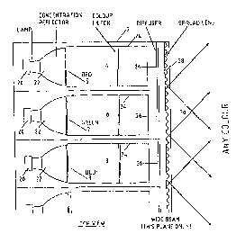
Système d'éclairage qui comporte une pluralité de sources (50) de lumière adjacentes de différentes couleurs. Chaque source de lumière possède un faisceau à grand angle dans un premier plan et un faisceau à angle plus petit dans un second plan pratiquement perpendiculaire au premier. Il en résulte un mélange efficace de la lumière dans le premier plan.


Abrégé anglais


A lighting system comprises a plurality of adjacent light sources (50) of
different colours. Each light source has a wide angle beam in a first plane
and a narrower angled beam in a substantial perpendicular second plane. As a
result, efficient mixing of light is achieved in the first plane.

Revendications

Note : Les revendications sont présentées dans la langue officielle dans laquelle elles ont été soumises.


-7-
CLAIMS
1. A lighting system comprising a plurality of
adjacent light sources of different colours, each light
source having a wide angled beam in a first plane and a
narrower angled beam in a substantially perpendicular
second plane whereby efficient mixing of light is achieved
in the first plane.
2. A lighting system according to claim 1 in which
the light sources are positioned behind a spread lens
which expands the beam width of the light sources in the
first plane.
3. A lighting system according to claim 2 in which
the spread lens comprises a set of parallel linear
prismatic refractors.
4. A lighting system according to claim 3 in which
the spread lens comprises a plurality of parallel
semi-specular elements.
5. A lighting system according to claim 3 in which
the spread lens comprises a set of parallel linear
prismatic reflectors.
6. A lighting system according to any of claims 2
to 5 including a diffuser positioned between each light
source and the spread lens.
7. A lighting system according to any preceding
claim comprising means for supplying power to each of the
light sources in desired proportions whereby predetermined
colours can be produced.

-8-
8. A lighting system according to claim 7
comprising means for controlling the means for supplying
power to the light sources in differing proportions such
that the plurality of predetermined colours may be
produced.
9. A lighting system according to claim 8 wherein
the means for controlling the means for supplying power to
the light sources comprises a rotary knob,
10. A lighting system according to claim 8 wherein
the means for controlling the means for supplying power to
the light sources comprises a slider.
11. A lighting system according to any preceding
claim in which the light sources are arranged in a linear
array.
12. A lighting system according to any of claims 1
to 10 in which the light sources are arranged in a
circular array, each pointing towards the centre of the
circle.
13. A lighting system according to claim 12 in
which the circular array surrounds a convex dome which
mixes and reflects light from the sources onto a surface
facing the convex surface of the dome.

Description

Note : Les descriptions sont présentées dans la langue officielle dans laquelle elles ont été soumises.


CA 02335279 2000-12-15
WO 99166257 PCT/GB99l01890
COLOUR WASH LIGHT
This invention relates to the mixing of a plurality
of electronica:Lly controlled light sources which are
filtered tc produce specific colours and then mixed to
make any one o:E a range of colours including, with
appropriate filtering, any colour in the visual spectrum.
Systems for mixing red, green and blue coloured light
to produce othe r colours has long been used to produce
colour television pictures. However, in the area of direct
lighting the larger the light sources and high powers
involved have made it difficult to produce beams of light
with homogeneous colour. This difficulty arises because of
the relatively large size of light sources and the fact
that a compromise has to be made between effective colour
1s mixing and efficient beams of light. Colour mixing can be
best achieved by diffusing the light whilst efficient
beams of light are produced by focusing the light.
A preferi:ed embodiment of the present invention
overcomes these problems by creating a wide angle mixing
2o beam in one plane of illumination whilst mainta~.ning a
narrow beam in a substantially perpendicular plane. Using
such a system makes it possible to illuminate a surface
with uniformly coloured light of any colour in the
spectrum using apparatus containing only three suitably
25 filtered light sources.
A further preferred embodiment of the invention uses
semi specular or linear prismatic reflectors combined with
small viewing shields to minimise the colour mixing zone
and obscure it. from view. This allows lighting units
3o embodying the invention to be mounted within low height
ceiling voids thus greatly enhancing the number of
applications t:o which they can be put.

CA 02335279 2000-12-15
WO 99166257 PCTlGB99/O1$90
- 2 -
In a further preferred embodiment the surface being
illuminated has its base inclined towards the viewer.
Preferably, a single action user interface is
incorporated which may be a rotary knob or a slider with a
purpose made colour scale that defines a set number of
colours or change cycles to enable the user to turn the
knob or slide the slider to a given colour and that colour
will appear.
The invention is defined in the appended claims to
to which reference should now be made.
A preferred embodiment of the invention will now be
described in detail by way of example with reference to
the accompanying drawings which:
Figs 1 and 2 show schematic block diagrams of systems
embodying the invention;
Fig. 3 is a schematic plan view of a lighting unit
embodying the invention;
Fig. ~ is a side view of a lighting unit for use at
the top of a wall to be illuminated
2o Fig. 5 is a front view of a similar unit.
Fig. 6 shows a variety of mounting arrangements for
the lighting emit; and.
Figures '7 and 8 show plan and side views of an
embodiment of the invention to be used behind e.g., a
picture hung on the wall.
The schematic diagram of Fig. 1 shows a lighting unit
2 containing t:.hree light sources. A red source 4, a green
source 6, and a blue source 8. Each of these is connected
to a voltage t=ransformer device 10 which supplies voltage
3o to operate each of the light sources, The human interface
12 with a rotary knob 14 supplies control signals to a
power control:Ler 16 which in turn supplies power to the
voltage transformers 10 in proportions dependent upon the
position o~ t:ne rotary knob 14. The human interface 12 is

CA 02335279 2000-12-15
WO 99/66257 PCf/GB99101890
- 3 -
able to supply control signals to supply power to the
voltage transformers 10 and thus to the light sources
4, 6, 8 in desired proportions so that any desired colour
can be obtained.
Alternatively in Figure 2, the schematic diagram
shows a lighting unit 2 containing three light sources, as
above, which are connected to a three channel combined
dimmer/transformer 15 which supplies power to operate each
of the light sources. The human interface 12 with a
1o rotary knob 14 supplies control signals direct to the
transformation. device 15 which in turn supplies power to
the lamps in proportion dependent upon the position of
rotary knob 14. The human interface 12 is able to supply
control signals to supply power to the light sources 4, 6,
8 in'desired proportions so that any desired colour can be
obtained.
The light sources 4, 6 and 8 are positioned adjacent
to each other and if a wider field of illumination is
required then additional banks of red, green and blue
light sources can be provided next to the lighting unit to
give whatever width of illumination is required.
The lighting unit is illustrated in more detail in
Fig. 3. Each of the light sources 4, 6 and 8 comprises a
lamp 20 positioned at the end of a.reflector 22 which
reflects light= through colour filters red 5, green 7, and
blue 9 from the lamp into a columniation tube 24. At the
end of each calumniation tube is a diffuser 26 which
diffuses the :Light from the light sources and transmits it
to a spread lens 28 which covers the whole of the front of
3o the lighting unit. This comprises a set of parallel semi-
specular or linear prismatic reflectors which are
perpendicular to the plane of Fig. 3 and which cause the
light to be diffused further up and down the plane of Fig.
3 as shown by the ray lines 30. Thus, the lighting unit
produces a wide beam up dmd :own the plane of Fig. 3

CA 02335279 2000-12-15
WO 99166257 PCT/GB99141890
- 4 -
whilst mair.~ai_ning a narrow beam in a plane perpendicular
to Fig. 3. =hip; gives very good mixing of the three
colours anc enables a Surface such as a wall to be washed
with the cc_oux:. This may be further enhanced by an
auxilliary =ef7.ector of either semi-specular or prismatic
material wh'_ch further mixes the colour and turns the beam
through an appropriate angle.
Fig. 4 shows a side view of a unit in which the
lighting ur_=t 2. of Fig. 3 can be mounted. The unit is thus
to perpendicular t:o its position in Fig 3 and the wide beam
of the unit is therefore perpendicular to the plane of
Fig. 4.
Usuailv unit 2 is mounted so that its primary
direction o~ i:llumination is perpendicular to a wall 32. A
reflector 3~ reflects the narrow beam of mixed light 36
downwards onto the wall 32. A shield 38 is provided to
stop a viewer geeing the mixing zone.
As car._ be seen, the wall 32 has its base inclined
towards the viewing side. This improves the uniformity of
2o illumination of the wall. Additionally, a mirror placed
at the base of the wall will reflect the beam back up the
wall and do,~ble the effect.
Alternatively, unit 2 can be mounted in the following
positions relative to the wall with the noted different
arrangements of lens and reflector and thus achieving the
effects described as shown in Figure 6.
1. ~'ounted to ceiling at an appropriate angle.
Unit s haT_1 have 7.inear refractor and no reflector
achieving a soft spread of light to the ceiling.
2. ?~:ounted in ceiling at right angles to wall.
Unit s~~a:Ll have a linear refractor lens and reflector
82 achieving a soft spread of coloured light on the
wall.
3. ~'_ounted to the ceiling at right angles to the
floor :axing linear raf_actor and no reflector

CA 02335279 2000-12-15
WO 99/66257 FCT/GB99/01890
- 5 -
achieving a soft spread of light on the wall. Effect
can be doubled by return mirror 80.
4. Mounted from the ceiling at right angles to
wall. Unit shall have a linear refractor lens and
s reflector 82 achieving a soft spread of coloured
light on the wall. Effect can be doubled by return
mirror 80.
5. Mounted in the floor at right angles to wall.
Unit shall have a linear refractor lens and reflector
l0 82 ac'_'_~.ieving a soft spread of coloured light on the
wall. Effect can be doubled by ceiling mounted
returr. mirror 80.
6. Mounted to the floor at right angles to
ceiling, using linear refractor and no reflector
15 achievinc; a soft spread of light on the wall and
ceiling. Effect can be doubled by ceiling mounted
return mirror 80.
7. (Not showny Mounted to ceiling at right angles
to floor. Unit shall have diffuser and columnating
20 .lens in place of a linear refractor achieving a
clearly defined circular area of light.
A front ~riew of the lighting unit 2 is shown in Fig
5. As can be seen the lighting unit is terminated by an
end of unit cu.t-off shield 40 to prevent any light
25 escaping to th,e side of the unit. The unit 2 is adjacent
to a further unit 2 and additional units may be fixed
adjacent tc this according to the width of illumination
required.
Using units as shown in Fig. 4 and Fig. 5 enables
30 lighting units embodying the invention to be mounted
within low height ceiling voids.
Alternatively, with a different arrangement of
reflector and cut-off shields the unit could be mounted at
the base o' a wall shinny light towards it.

CA 02335279 2000-12-15
WO 99166257 PCTlGB99/01890
- 6 -
The knob :14 on the human interface I2 is a single
action knob and has a colour scale around it such that
control sequences are sent to the power controller to send
power to the voltage transformers 10 in desired
proportions to ensure that a desired colour is produced by
the lighting unit. This is intended to simplify the three
separate controls which would usually be provided for the
red, green and blue light sources.
The embodiment described above shows the use of red,
to green and blue light sources which will enable any colour
in the spectrum to be produced with appropriate control
signals. However, the invention could also be used with
only two light sources, thus giving a narrower range of
available colours.
The unit need nat be used to produce only a wash of
light. Using a suitable arrangement of lenses, the unit
could be used to produce e.g., a focused beam of light.
Such an application is shown in Figure 7 and 8 which shows
a diagram of the invention arranged as a "Picture Light"
2o as it is mounted behind e.g., a picture hung on the wall.
Lamps 50,, connected to transformers as described
above, project. a narrow beam of light through dichroic
filters in reel 52, green 54, and blue 56 this coloured
light passes along tubes 58 and is diffused by diffuser 60
and spread by refractor 62, the three beams mix into a
single colour with the help of a diffusing dome 64 which
reflects and mixes the diffused light. The groups of
three lamps and optical system are repeated around the
dome 64 to form a continuous ring. The assembly is hung a
3o small distance from a surface with the course surface of
the dome towards the surface, and illuminates the surface
with whatever colour the user sets with the control system
described above. This happens as light is reflected and
mixed by the course surface of the dome onto the surface
to be illuminated.

Dessin représentatif
Une figure unique qui représente un dessin illustrant l'invention.
États administratifs

2024-08-01 : Dans le cadre de la transition vers les Brevets de nouvelle génération (BNG), la base de données sur les brevets canadiens (BDBC) contient désormais un Historique d'événement plus détaillé, qui reproduit le Journal des événements de notre nouvelle solution interne.

Veuillez noter que les événements débutant par « Inactive : » se réfèrent à des événements qui ne sont plus utilisés dans notre nouvelle solution interne.

Pour une meilleure compréhension de l'état de la demande ou brevet qui figure sur cette page, la rubrique Mise en garde , et les descriptions de Brevet , Historique d'événement , Taxes périodiques et Historique des paiements devraient être consultées.

Historique d'événement

Description Date
Inactive : CIB attribuée 2021-12-07
Inactive : CIB expirée 2018-01-01
Inactive : CIB enlevée 2017-12-31
Inactive : CIB désactivée 2011-07-29
Inactive : CIB de MCD 2006-03-12
Inactive : CIB dérivée en 1re pos. est < 2006-03-12
Inactive : CIB de MCD 2006-03-12
Demande non rétablie avant l'échéance 2004-06-15
Le délai pour l'annulation est expiré 2004-06-15
Réputée abandonnée - omission de répondre à un avis sur les taxes pour le maintien en état 2003-06-16
Lettre envoyée 2002-07-29
Exigences de rétablissement - réputé conforme pour tous les motifs d'abandon 2002-07-17
Réputée abandonnée - omission de répondre à un avis sur les taxes pour le maintien en état 2002-06-17
Lettre envoyée 2001-05-03
Inactive : Page couverture publiée 2001-04-09
Inactive : Transfert individuel 2001-04-02
Inactive : CIB en 1re position 2001-03-25
Inactive : Lettre de courtoisie - Preuve 2001-03-20
Inactive : Notice - Entrée phase nat. - Pas de RE 2001-03-14
Demande reçue - PCT 2001-03-12
Demande publiée (accessible au public) 1999-12-23

Historique d'abandonnement

Date d'abandonnement Raison Date de rétablissement
2003-06-16
2002-06-17

Taxes périodiques

Le dernier paiement a été reçu le 2002-07-17

Avis : Si le paiement en totalité n'a pas été reçu au plus tard à la date indiquée, une taxe supplémentaire peut être imposée, soit une des taxes suivantes :

  • taxe de rétablissement ;
  • taxe pour paiement en souffrance ; ou
  • taxe additionnelle pour le renversement d'une péremption réputée.

Les taxes sur les brevets sont ajustées au 1er janvier de chaque année. Les montants ci-dessus sont les montants actuels s'ils sont reçus au plus tard le 31 décembre de l'année en cours.
Veuillez vous référer à la page web des taxes sur les brevets de l'OPIC pour voir tous les montants actuels des taxes.

Historique des taxes

Type de taxes Anniversaire Échéance Date payée
Taxe nationale de base - petite 2000-12-15
Enregistrement d'un document 2001-04-02
TM (demande, 2e anniv.) - petite 02 2001-06-15 2001-06-04
Rétablissement 2002-07-17
TM (demande, 3e anniv.) - petite 03 2002-06-17 2002-07-17
Titulaires au dossier

Les titulaires actuels et antérieures au dossier sont affichés en ordre alphabétique.

Titulaires actuels au dossier
ISOMETRIX LIGHTING & DESIGN LIMITED
Titulaires antérieures au dossier
ARNOLD CHAN
JONATHAN COLES
Les propriétaires antérieurs qui ne figurent pas dans la liste des « Propriétaires au dossier » apparaîtront dans d'autres documents au dossier.
Documents

Pour visionner les fichiers sélectionnés, entrer le code reCAPTCHA :


Pour visualiser une image, cliquer sur un lien dans la colonne description du document. Pour télécharger l'image (les images), cliquer l'une ou plusieurs cases à cocher dans la première colonne et ensuite cliquer sur le bouton "Télécharger sélection en format PDF (archive Zip)" ou le bouton "Télécharger sélection (en un fichier PDF fusionné)".

Liste des documents de brevet publiés et non publiés sur la BDBC .

Si vous avez des difficultés à accéder au contenu, veuillez communiquer avec le Centre de services à la clientèle au 1-866-997-1936, ou envoyer un courriel au Centre de service à la clientèle de l'OPIC.


Description du
Document 
Date
(aaaa-mm-jj) 
Nombre de pages   Taille de l'image (Ko) 
Dessin représentatif 2001-04-08 1 11
Description 2000-12-14 6 285
Abrégé 2000-12-14 1 66
Revendications 2000-12-14 2 64
Dessins 2000-12-14 7 140
Rappel de taxe de maintien due 2001-03-13 1 112
Avis d'entree dans la phase nationale 2001-03-13 1 194
Courtoisie - Certificat d'enregistrement (document(s) connexe(s)) 2001-05-02 1 113
Courtoisie - Lettre d'abandon (taxe de maintien en état) 2002-07-14 1 183
Avis de retablissement 2002-07-28 1 170
Courtoisie - Lettre d'abandon (taxe de maintien en état) 2003-07-13 1 174
Rappel - requête d'examen 2004-02-16 1 113
Correspondance 2001-03-13 1 24
PCT 2000-12-14 9 465
Taxes 2001-06-03 1 40
Taxes 2002-07-16 1 43