Note : Les descriptions sont présentées dans la langue officielle dans laquelle elles ont été soumises.
CA 02336289 2001-03-O1
IMPROVED FLANGE NUT
BACKGROUND OF THE INVENTION
1. Field of the Invention
[0001 ) The present invention relates to threaded fasteners and, more
particularly,
to flange nuts used as mixing delay devices in mine roof bolt installations.
2. Description of the Prior Art
[0002) Mine roof bolts, bearing plates, and resin/catalyst cartridges are
often used
in mine roof support systems. In a general installation, the resin/catalyst
cartridge is
inserted into the bore hole, followed by a first end of the mine roof bolt. A
second
externally-threaded end of the mine roof bolt is generally positioned through
an orifice
defined by the mine roof plate. In tensionable mine roof bolts, a threaded nut
is usually
received on the second externally-threaded end of the mine roof bolt.
[0003] The mine roof bolt is then rotated, causing the resin/catalyst to mix
and
ultimately cure. If the threaded nut is permitted to advance toward the first
end of the
mine roof bolt during mixing, the mine roof bolt will not rotate properly, and
the
resin/catalyst will not mix. Therefore, it is advantageous to delay the
advancement of the
threaded nut until the resin has cured. Once cured, the resin prevents further
rotation of
the mine roof bolt, and the threaded nut may then be advanced toward the first
end of the
mine roof bolt, securely holding the bearing plate in place and allowing the
cable bolt to
be tensioned.
[0004) There are multiple prior art methods and structures which have sought
to
initially fix a threaded or non-threaded nut during rotation of the mine roof
bolt. These
methods include the use of delay mechanisms, such as shear pins or plaster
thread inserts,
as well as various nut thread arrangements.
CA 02336289 2001-03-O1
[0005] For example, U.S. Patent No. 3,979,918 to Vidler teaches deformations
positioned adjacent to one end of an inner threading of a nut. These
deformations allow
the nut to cease rotating with respect to the mine roof bolt when the area of
the
deformations is reached. Continued rotation of the nut after the deformations
are reached
causes the entire mine roof bolt to rotate, mixing the resin/catalyst. Once
the
resin/catalyst hardens, continued rotation of the nut causes the mine roof
bolt to defeat
the deformations, allowing the nut to advance along a length of the mine roof
bolt.
[0006] U.S. Patent No. 5,282,698 to Wright et al. discloses a threaded
fastener
or nut with longitudinally-extending, V-shaped notches at an end of the nut.
When the
resin/catalyst has hardened and a mine roof bolt ceases to rotate, continued
rotation of the
nut pushes the V-shaped notches away from the mine roof bolt, allowing the nut
to be
further tightened.
(0007] U.S. Patent No. 5,417,520 to Rastall discloses an internally-threaded
nut
with dimples stamped on a flat portion of an end of the nut to deform the
internal threads.
These dimpled areas allow the mine roof bolt and internally-threaded nut to be
uniformly
rotated until the resin/catalyst hardens. Once the resin/catalyst hardens, the
dimples yield
to the mine roof bolt, allowing the threaded nut to advance along a length of
the mine
roof bolt.
[0008] Finally, U.S. Patent No. 5,954,456 to Bowles discloses an
internally-threaded nut having an outwardly-extending end portion, which is
coined to
reduce the pitch of the threads at an end of the nut. As with the previously-
discussed
patents, this reduction in thread pitch near the end of the internally-
threaded nut allows
the internally-threaded nut to be rotated relative to the bolt until these
lower-pitched
threads are reached. After the lower-pitched threads are reached, the
internally-threaded
-2-
CA 02336289 2001-03-O1
nut and mine roof bolt rotate together until the resin/catalyst hardens. At
this point,
further torque on the internally-threaded nut forces the nut along a length of
the mine roof
bolt, allowing the internally-threaded nut to be torqued.
[0009] There are several drawbacks of the prior art nut elements. Expensive
tooling costs can be involved in pitch reduction, dimpling, creation of a dome
structure,
or creating other hard-to-machine deformations or indentations. It is also
often necessary
to control, within acceptable limits, the breakout torque for the nut, and the
prior art
methods have limitations on the breakout torque. Hence, a need remains for an
improved
flange nut which is easy to manufacture, has reduced machining costs, and can
meet
varying breakout requirements for the nut.
SUMMARY OF THE INVENTION
[0010) The present invention seeks to obviate the disadvantages of the prior
art
by providing a nut having a nut body, a first end, a second end, and defining
an orifice
extending between the first end and the second end. A plurality of first
threads and a
malformed thread are each positioned in the orifice defined by the nut body,
wherein the
malformed thread interrupts continuity of at least one of the plurality of
first threads.
(0011] The nut body further defines an interior nut wall. The malformed thread
may be an untapped portion of the interior nut wall, a partially tapped
thread, a thread
which has been stripped, or any thread having a thread height which is larger
than a
thread height of any one of the plurality of first threads.
[0012] In general, one method of producing a nut according to the present
invention includes the steps of: (a) making a nut body having a first end and
a second
end; (b) defining an orifice in the nut body which extends between the first
end and the
second end; (c) positioning a plurality of first threads in the orifice
defined by the nut
_ J _
CA 02336289 2004-04-O1
body; and (d) interrupting the plurality of first threads with a malformed
thread. The
step of interrupting the plurality of first threads with a malformed thread
may be
accomplished by stripping one of the plurality of uniformly-pitched first
threads,
partially tapping the interior nut wall, not tapping a portion of the interior
nut wall, or
forming a thread having a thread height greater than the thread height of any
one of
the plurality of first threads.
[0013] In one exemplary application, a resin mixing delay system for mine
roof support is also provided. The system generally includes a mine roof bolt
having a
first bolt end defining a plurality of external threads and a flange nut body.
The flange
nut body has a first end, a second end, and defines an orifice extending
between the
first end and the second end. A plurality of uniformly-pitched first threads
are
positioned in the orifice defined by the flange nut body, with each of the
plurality of
uniformly-pitched threads having a substantially equal thread height. At least
one
malformed thread positioned in the orifice defined by the body. The malformed
thread
has a thread height that is greater than or less than the thread height of any
one of the
plurality of uniformly-pitched threads.
[0014) In this example, the plurality of uniformly-pitched first threads
receives the plurality of external threads defined by the first bolt end of
the mine roof
bolt. The mine roof bolt has a second bolt end and may further include a
mechanical
anchor positioned between the first bolt end and the second bolt end. The
flange nut
body may further define an enlarged cavity portion adjacent to the first end
of the
flange nut, a square-shaped drive head, and a flange.
[0014a] According to another aspect of the present invention there is provided
a nut configured to be threaded onto a shaft that defines external threads.
The nut
comprises a nut body having a receiving end, a second end opposite the
receiving end,
4
CA 02336289 2004-04-O1
and defining an orifice extending between the receiving end and the second
end. A
plurality of first threads is positioned at the receiving end in the orifice
defined by the
nut body. Each of the first threads has a uniform height and a uniform pitch
and
forms lead-in threads for the nut. A malformed thread is positioned in the
orifice
defined by the nut body following the first threads. The malformed thread has
a
thread height which is different than the uniform height of the plurality of
first threads
and a pitch, as measured from a neighboring one of the plurality of first
threads,
which is substantially equal to the uniform pitch of the first threads. The
malformed
thread interrupts continuity of at least one of the plurality of first threads
for
temporarily preventing the nut from being advanced along the externally
threaded
shaft, wherein at the application of a predetermined torque on the nut the
malformed
thread is tapped by the external threads of the shaft.
4a
CA 02336289 2004-04-O1
[0014b] According to another aspect of the present invention there is provided
a resin mixing delay system comprising a mine roof bolt having a first bolt
end
defining a plurality of external threads and a flange nut body that is
rotatably
connected to one end of the mine roof bolt. The flange nut body has a
receiving end
for receiving the external threads of the bolt and a second end opposite the
receiving
end and defining an orifice extending between the receiving end and the second
end.
A plurality of first threads is positioned at the receiving end in the orifice
defined by
the flange nut body. The plurality of first threads each has a uniform height
and a
uniform pitch and forming lead-in threads for the flange nut body. At least
one
malformed thread is positioned in the orifice defined by the flange nut body
following
the first threads. The malformed tread has a height that is different than the
uniform
height of any one of the plurality of first threads, and a pitch, as measured
from a
neighboring one of the plurality of first threads, which is substantially
equal to the
uniform pitch of the first threads. The malformed thread interrupts continuity
of at
least one of the plurality of first threads for temporarily preventing
rotation of the
flange nut body with respect to the mine roof bolt, wherein at the application
of a
predetermined torque on the flange nut body the malformed thread is tapped by
the
external threads of the mine roof bolt.
[0015] It is, therefore, an object of the present invention to provide an
improved flange nut which is easy to manufacture and requires low
manufacturing
costs. It is a
4b
CA 02336289 2001-03-O1
further object of the present invention to provide a flange nut for torque
tension
applications where the breakout torque is tightly controlled.
[0016] The invention, both as to its construction and its method of operation,
together with additional objects and advantages thereof, will best be
understood from the
following description of specific embodiments when read in connection with
accompanying drawings.
BRIEF DESCRIPTION OF THE DRAWINGS
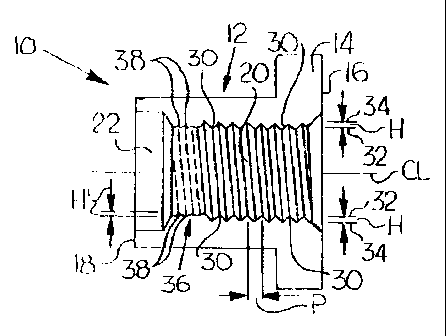
[0017] Fig. 1 is a cross-sectional side view of a nut according to one
embodiment
of the present invention;
[0018] Fig. 2 is an end view of the nut shown in Fig. l;
[0019] Fig. 3 is a cross-sectional side view of a nut according to a second
embodiment of the present invention;
[0020] Fig. 4 is a cross-sectional side view of a nut according to a third
embodiment of the present invention;
[0021] Fig. 5 is a cross-sectional side view of a nut according to a fourth
embodiment of the present invention; and
[0022] Fig. 6 is a side view of one type of mine roof support system having a
mine roof bolt, a bearing plate, and the nut shown in Figs. 1 and 2.
DETAILED DESCRIPTION OF THE PREFERRED EMBODIMENTS
[0023] Figs. 1 and 2 show a nut 10, such as a flange nut 12, according to a
first
embodiment of the present invention. As shown in Fig. 1, the nut 10 generally
includes
a nut body 14 having a first end 16, a second end 18, and defining an orifice
20 extending
between the first end 16 and the second end 18 along an imaginary centerline
CL. The
nut body 14 may further define an enlarged orifice portion 22, which is in
fluid
-5-
CA 02336289 2001-03-O1
connection with the orifice 20, and an internal nut wall 24, as shown in Fig,
2. While
Fig. 2 shows a flange nut 12 having a sciuare-shaped head 26 and a flange 28,
other nut
shapes are clearly contemplated.
[0024] ~s shown generally in Fig. 1, a plurality of first threads 30 of any
suitable
type are each positioned in the orifice 20 defined by the nut body 14. Fur
purposes of this
description, a first thread 30 is herein generally defined as a ridge, such as
a continuous
spiral shaped ridge, having an apex 32 and a nadir 34. More particularly, the
apex 32 of
each first thrca~d 30 extends toward the imaginary centerline CL of the
orifice 20 defined
by the nut body 14. The plurality of first threads 30 arc preferably formed by
tapping the
nut body 14 in a conventional manner.
[U025j With continuing reference to Fig. 1, the plurality of first threads 30
each
preferably have a substantially uniform thread height H and two or more of the
plurality
of first threads 30 have a uniform pitch P. Thread height H is generally
defined herein
as a measured distance betweer, an apex = 2 of a first thread 3 0 and the
corresponding
nadir 34 of each first thread 30. Pitch P is generally defined herein as the
spacing
between apexes 32 of neighboring first threads 30.
[0026) At least one malformed thread 3 6 is also positioned in the orifice 20
defined by the nut body 14, wherein the malformed thread 36 interrupts
continuity of at
least one of the plurality of fast threftds 30. A thread height Fi' of the at
least one
mxlrormed thrarad ,'sti tray oe ~ea:rr urn. i~;ss t:~.ae, or equal to :ilc tiu-
~3d he:ant i-i of one
or more of the plurality of first threads 30.
[0027] Fig. 1 shows a first embodiment of a nut 10 according to the present
invention having a plurality of first threads 30 and at least one malformed
thread 36
positioned in the orifice 20 defined by the nut body 14. In this embodiment,
the first
-6-
CA 02336289 2001-03-O1
threads 30 and the at least one malformed thread 36 are continuous, and the
malformed
thread or threads 36 are only partially-formed threads 38, preferably formed
by only
partially tapping the nut body 14.
[0028] Fig. 3 shows a nut 10' according to a second embodiment of the present
invention. In Fig. 3, the plurality of first threads 30 and at least one
malformed thread
36 are each positioned in the orifice 20 defined by the nut 10', with the
plurality of first
threads 30 and the malformed threads 36 being continuous. However, in this
second
embodiment 10', the at least one malformed thread 36 is a thread, such as
first thread 30
or some other type of threads, is a stripped thread 40. Stripping, which
commonly occurs
when a threaded nut is overtightened on a threaded bolt, may be done by
coining or some
other type of process.
[0029] Fig. 4 shows a third embodiment nut 10" according to the present
invention. In this embodiment, the malformed thread 36 is an unthreaded
portion 42 of
the interior nut wall 24. In operation, when the nut 10" is threadedly
attached to an
externally-threaded bolt, the external threads defined by the bolt tap the
unthreaded
portion 42 of the interior nut wall 24.
[0030] Finally, a fourth embodiment nut 10"' according to the present
invention
is shown in Fig. 5. In this fourth embodiment, the malformed thread 36 has a
thread
height H", which is greater than the thread height H any one of the plurality
of first
threads 30. In operation, this larger thread 44 is stripped by external
threads of a bolt.
[0031] The plurality of first threads 30 may be used with any of the malformed
threads 36 discussed above, or in any combination. However, it is desirable to
threadingly engage any embodiment of the present invention with an externally-
threaded
end of a bolt, such as the mine roof bolt 46 shown in Fig. 6. Therefore, the
plurality of
_7-
CA 02336289 2001-03-O1
first threads 30 are preferably positioned in the orifice 20, adjacent to the
first end 16 of
the nut 10, so as to engage the externally-threaded end 48 of the mine roof
bolt 46 before
the externally-threaded end 48 of the mine roof bolt 46 reaches the at least
one
malformed thread 36.
[0032] In general, one method of producing a nut 10 according to any of the
embodiments of the present invention includes the step of making a nut body 14
having
a first end 16 and a second end 18. The next preferred step is defining an
orifice 20 in
the nut body 14 which extends between the first end 16 and the second end 18.
Other
steps include positioning a plurality of first threads 30 in the orifice 20
defined by the nut
body 14 and interrupting the plurality of first threads 30 with a malformed
thread 36.
[0033] In order to control the breakout torque of a flange nut 12 in mine roof
support applications, metallurgical properties and thread tapping should be
controlled to
achieve the combinations necessary to achieve the desired breakout torque. In
mine roof
support applications, delay mechanisms which create 90-120 foot pounds of
breakout
torque may be sufficient. However, with faster setting resins, spinners are
now more
frequently encountered. A spinner generally refers to a mine roof bolt that
spins in the
bore hole without sufficient engagement with the bore hole (i.e., it spins).
Therefore, for
a standard #6 rebar bolt with 3/4" threads, a breakout torque on the order of
200 foot
pounds or more may be required.
[0034] Adequate breakout torque may be achieved by constructing a nut from
ASTM 536-84 specification steel. The preferred chemistry is a ductile iron
having a
weight percent composition of approximately 3.5-3.9% C; approximately 2.2-2.9%
S; a
maximum of approximately 0.80% Mn; a maximum of approximately 0.05% P; a
maximum of approximately 0.02% S; approximately 0.025-0.075% Mg; 0.20-1.2% Cu;
_g_
CA 02336289 2001-03-O1
and the balance being iron and incidental impurities. The nuts 10 are then
cast into
appropriate shapes by molds, and the cooling of the parts is controlled in
conjunction
with the composition to give a desired hardness for the castings. A BHN
hardness of 211
has been found satisfactory, whereas a BHN hardness of 249 has been found only
partially acceptable.
[0035) In addition to controlling thread pitch P and height H, it has been
found
that it is important to control tap depth TD along centerline CL, as shown in
Fig. 4. Tap
depth TD is defined herein as the overall length of the tap between the last
full thread of
the plurality of first threads 30 and the second end 18 of the nut body 14.
For example,
for a mine roof bolt 46 made tiom #6 rebar having a 3/4" external thread and a
breakout
torque of 200 foot pounds, it has been found that the tap depth TD should be
0.450 inches. As the tap depth TD increases, the breakout torque also
increases.
[0036] While it is a mechanism which allows for the adjustment of breakout
torque, it is recognized that the residual torque, that is, the torque to turn
the nut 10 after
breakout, may also be increased. Since it is desirable to keep the residual
torque as low
as possible, lubrication, such as by coating the externally-threaded end 48 of
the mine
roof bolt 46, can be utilized. Notching the externally-threaded end 48 of the
mine roof
bolt 46 is an additional mechanism for preventing deformation of the
externally-threaded
end 48.
[0037] Installing a nut 10 according to the present invention in a mine roof
support system is generally shown in Fig. 6. A bore hole 50 is created in
earth and rock
in a roof 52 of the mine. The bore hole 50 is particularly adapted to
receiving a
resin/catalyst 54 and a mine roof bolt 46. This resin/catalyst 54, usually a
cartridge that
includes both a resin/catalyst and adhesive, is inserted into the bore hole 50
defined by
-9-
CA 02336289 2001-03-O1
the mine roof 52, and, thereafter, a second end 56 of the mine roof bolt 46 is
also inserted
into the bore hole 50. A first end 58 of the mine roof bolt 46 is placed
through an orifice
60 defined by a bearing plate 62. In practice, the nut 10 is preferably
preassembled on
a first end 58 of the mine roof bolt 46, all the way to the at least one
malformed thread
36 positioned in the orifice 20 defined by the nut body 14
[0038] The nut 10 is rotated, causing the mine roof bolt 46 to rotate in the
bore
hole 50 and then mix the resin/catalyst 54 to form an adhesive. As the
adhesive cures,
the rotation of the nut 10 and mine roof bolt 46 can no longer continue with
the uniform
torque previously applied.
[0039] As the nut 10 is rotated further around the now stationary mine roof
bolt
46, the externally-threaded end 48 of the mine roof bolt 46 forms or reforms
new threads
in the orifice 20 defined by the nut body I4. The externally-threaded end 48
of the mine
roof bolt 46 then continues through the newly-tapped or retapped malformed
threads 36,
allowing the nut 10 to advance along a length of the mine roof bolt 46. In
this manner,
the nut 10 can be further threaded snugly against the bearing plate 62 to
tension the
system against the mine roof 52.
[0040] The present invention is an economically-feasible nut with low-tooling
costs. Further, the nut is easily manufactured, requires no additional tooling
equipment
and requires no additional appurtenances on the end of the nut. Since no shear
pin or
other external material is required as a delay mechanism, contamination with
other
mining equipment is avoided. Also, by coordinating the physical properties of
the
plurality of first threads and the external bolt threads with the thread
dimensions and the
tap depth, desired and reproducible breakout torques can be achieved.
-10-
CA 02336289 2001-03-O1
[0041] The invention has been described with reference to the preferred
embodiments. Obvious modifications and alterations will occur to others upon
reading
and understanding the preceding detailed description. It is intended that the
invention be
construed as including all such modifications and alterations insofar as they
come within
the scope of the appended claims or equivalents thereof.