Note : Les descriptions sont présentées dans la langue officielle dans laquelle elles ont été soumises.
CA 02337146 2005-07-08
62616-150(S)
1
SPECTACLE FRAMES
Technical Field
The present invention relates to spectacle frames,
and in particular relates to spectacle frame assemblies having
a primary spectacle frame and a detachable auxiliary spectacle
frame.
Background of the Invention
To enable the use of sunglass lenses with spectacles
having prescription lenses, various forms of "clip-on"
detachable auxiliary spectacle frames have been proposed which
allow the auxiliary frame housing sunglass lenses to be clipped
onto the frame front of the primary spectacle frame housing the
prescription lenses via various forms of clips. The success of
the various forms of clips varies in terms of security of
attachment, non-intrusive appearance and ease of
attachment/detachment.
Replacement of the clip type attachment means with
cooperating magnetic attachments on both the primary and
auxiliary spectacle frames has also been proposed. The
security of attachment of currently available spectacle frame
assemblies of this type is quite poor, however, with the
auxiliary spectacle frame typically being free to rattle,
vibrate or flicker and possibly disengage with any jarring
movements of the wearer, such as during various forms of
exercise. Rattling, vibrating or flickering of the auxiliary
spectacle frame can be uncomfortable and possibly harmful to
the human eye by causing optical distortion as well as rapid
variations in light levels if light is able to pass around the
tinted lenses of the auxiliary spectacle frames when displaced.
CA 02337146 2005-07-08
62616-150(S)
2
Object of the Invention
It is the object of the present invention to overcome
or substantially ameliorate at least some of the above
disadvantages.
Summary of the invention
There is disclosed herein a spectacle frame assembly
comprising: a primary spectacle frame having a primary frame
front provided with a pair of primary frame arms toward
respective laterally outer ends thereof, a pair of temples
pivotally coupled to respective said primary frame arms and a
pair of primary frame lugs secured to respective said primary
frame arms, and an auxiliary spectacle frame having a pair of
auxiliary frame lugs disposed at respective laterally outer
ends thereof, each said auxiliary frame lug being engageable
with a corresponding said primary frame lug for securing said
auxiliary spectacle frame to said primary spectacle frame;
wherein, for each pair of corresponding primary and auxiliary
frame lugs, one of said primary and auxiliary frame lugs is
provided with a magnetic member receivable in an open cavity
provided in the other one of said primary and auxiliary frame
lugs, said open cavity having a peripheral wall for engaging a
peripheral wall of said magnetic member and an end wall for
engaging an end surface of said magnetic member, said open
cavity peripheral wall being formed at least partially of a
ferrous material and said end walls being formed at least
partially of the ferrous material, said ferrous material not
being a magnet.
Typically, said auxiliary spectacle frame is provided
with a pair of auxiliary frame arms toward respective said
opposing laterally outer ends thereof, said
CA 02337146 2004-04-20
62616-150(S)
2a
auxiliary frame lugs being secured to respective said
auxiliary frame arms.
Typically said primary frame lugs are disposed
rearwardly of said primary frame arms, said auxiliary frame
CA 02337146 2003-09-22
62616-150
3
arms being adapted to extend over said primary frame arms to
enable engagement of said primary and auxiliary frame lugs.
Typically, each of said primary frame lugs is
provided with a said magnetic member and each of said auxiliary
frame lugs is provided with a said open cavity.
Typically each said primary frame lug comprises a
ring secured to the respective said primary frame arm and a
said magnetic member secured in said ring such that said
magnetic member peripheral wall protrudes above said ring.
Typically each of said auxiliary frame lugs
comprises a hollow cylinder secured to the respective said
auxiliary frame arm, said open cavity being defined by the
hollow of said hollow cylinder.
Preferably each said auxiliary frame lug is made
substantially entirely of ferrous material.
Preferably, each said magnetic member is
cylindrical and said magnetic member peripheral wall protrudes
above said ring a distance approximately one quarter the
diameter of said magnetic member.
Preferably, each said magnetic member has a
diameter of approximately 4 mm.
Preferably a lower surface of each said primary
frame lug is substantially flush with a lower surface of the
respective said primary frame arm. It is also preferred that an
upper surface of each said primary frame lug is substantially
flush with an upper surface of the respective said primary
frame arm.
CA 02337146 2003-09-22
62616-150
4
Alternatively, each of said auxiliary frame lugs is
provided with a said magnetic member and each of said primary
frame lugs is provided with a said open cavity.
Typically said primary frame front includes a pair
of primary frame rims for receiving a pair of primary lenses
and a primary frame bridge secured to and separating said
primary frame rims, said primary frame arms being secured to
laterally outer portions of each of said primary frame rims.
Alternatively said primary frame front includes a
pair of primary lenses and a primary frame bridge secured
directly to and separating said primary lenses, said primary
frame arms being secured directly to laterally outer portions
of each of said primary lenses.
Typically said auxiliary spectacle frame includes a
pair of auxiliary frame rims for receiving a pair of auxiliary
leases and an auxiliary frame bridge secured to and separating
said auxiliary frame rims, said auxiliary frame arms being
secured to laterally outer portions of each of said auxiliary
frame rims.
Alternatively said auxiliary spectacle frame
includes a pair of auxiliary lenses and an auxiliary frame
bridge secured directly to and separating said auxiliary
lenses, said auxiliary frame arms being secured directly to
laterally outer portions of each of said auxiliary lenses.
Preferably said auxiliary frame bridge extends over
and engages said primary frame bridge.
Typically each said auxiliary frame lug is disposed
on top of said corresponding primary frame lug.
CA 02337146 2003-09-22
62616-150
4a
Brief Description of the Drawings
Preferred forms of the present invention will now
be described by way of example with reference to the
accompanying drawings wherein:
Figure 1 is a front elevation view of a primary
spectacle frame.
Figure 2 is a rear elevation view of the primary
spectacle frame of Figure 1.
Figure 3 is a plan view of the primary spectacle
frame of Figure 1.
Figure 4 is a front elevation view of an auxiliary
spectacle frame.
Figure 5 is a plan view of the auxiliary spectacle
frame of Figure 4.
CA 02337146 2001-O1-15
WO 00/33124 PCT/AU99/00339
Figure b is a front elevation view of a spectacle frame assembly of the
primary
spectacle frame of Figure 1 and the auxiliary spectacle frame of Figure 4.
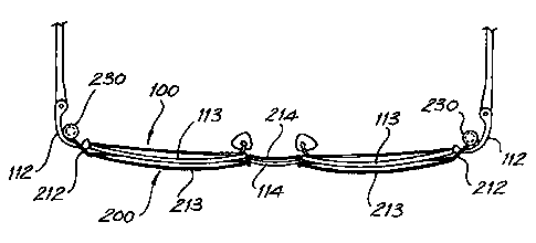
Figure 7 is a plan view of the spectacle frame assembly of Figure 6.
Figure 8 is a schematic cross sectional view of a primary frame lug secured to
an
5 auxiliary frame lug.
Figure 9 is a schematic isometric view from below of a primary frame lug and
an
auxiliary frame lug.
Figure 10 is a front elevation view of a rimless primary spectacle frame.
Figure 11 is a rear elevation view of the rimless primary spectacle frame of
Figure 10.
Figure 12 is a plan view of the rimless primary spectacle frame of Figure 10.
Figure 13 is a front elevation view of a rimless auxiliary spectacle frame.
Figure 14 is a plan view of the rimless auxiliary spectacle frame of Figure
13.
Detailed Description of the Preferred Embodiments
With reference to Figures 1 through 9, a first embodiment of the current
invention
provides a spectacle frame assembly comprising a primary spectacle frame 100
and an
auxiliary spectacle frame 200 which can be secured to the primary spectacle
frame 100.
The primary spectacle frame 100 will typically house prescription lenses, with
the
auxiliary spectacle frame 200 housing tinted sunglass lenses as per common
"clip on"
assemblies.
The primary spectacle frame 100 has a primary frame front 110, a pair of
temples
120 for engaging the ears and the sides of the wearer's head pivotally coupled
to laterally
outer ends 111 of the primary frame front 110 and a pair of primary frame lugs
I30
which are secured to the primary frame front 110 adjacent the laterally outer
ends 111 of
the primary frame front 110. For a conventional primary spectacle frame 100,
the
primary frame front 110 will typically be provided with a primary frame arm l
I2 toward
each lateral end 111 with the temples 120 being pivotally coupled to the
primary frame
arms 112 and the primary frame lugs 130 secured to the primary frame arms 112.
For
CA 02337146 2001-O1-15
WO 00/33124 PCT/AU99/00339
8
spectacle frame designs without distinct arms 112, however, the primary frame
lugs 130
can still be suitably secured to the frame adjacent the primary frame front
lateral ends.
The auxiliary spectacle frame 200 has a pair of auxiliary frame lugs 230
disposed at
laterally outer ends 211 thereof. The auxiliary frame lugs 230 are typically
secured to
auxiliary frame arms 212 provided toward each laterally outer end of the
auxiliary frame
200. The auxiliary frame lugs 230 are each engageable with the corresponding
primary
frame lug 130 with the auxiliary frame lug 230 disposed on top of the
corresponding
primary frame lug 130, as depicted in Figures 6 and 7 to secure the auxiliary
spectacle
frame 200 to the primary spectacle frame 100.
As best depicted in Figures 8 and 9, each primary frame lug 130 is provided
with a
magnetic member 131 which is received in an open cavity 231 provided in the .
corresponding auxiliary frame lug 230. The open cavity 231 has a peripheral
wall 232,
which is here cylindrical, which engages a corresponding peripheral wall I32
of the
magnetic member 131, which is here also cylindrical. The magnetic member 131
is
hence retained in the open cavity 231, and the auxiliary frame lug 230 can not
readily
slide off the top of the primary frame lug 130 to detach the auxiliary frame
200 from the
primary frame 100 as is the case with currently available magnetically
attached auxiliary
frames. The auxiliary frame lug 230 is at least partially formed of a ferrous
material to
facilitate the magnetic securing of the auxiliary frame lug 230 to the primary
frame lug
130. The auxiliary frame lug 230 is hence secured to the primary frame lug by
both a
magnetic force and the physical connection of the magnetic member peripheral
wall 132
to the auxiliary frame lug 230 within the open cavity 231. The auxiliary
spectacle frame
200 of the preferred embodiment is thus restrained against horizontal and
vertical
movement relative to the primary spectacle frame 100. The current applicant
refers to the
secure spectacle assembly thus provided by the engaging magnetic members 131
and open
cavities 231 as a mono-magnetic clip-on assembly (MMCA).
In the preferred embodiment the entire auxiliary frame lug 230, and in fact
the
entirety of the auxiliary spectacle frame 200, is formed of steel. The primary
spectacle
frame 100 is also formed largely of steel, however persons skilled in the art
will
appreciate that the current invention is applicable to primary and secondary
spectacle
CA 02337146 2001-O1-15
WO 00/33124 PCT/AU99/00339
_ 7
frames of any suitable material, typically metallic or plastic, so long as the
auxiliary
frame lugs 230 are at least partially formed of ferrous material for
cooperating with the
magnetic members 131.
Each primary frame lug 130 comprises a ring 134 which is secured to the
primary
frame arm 112, here by soldering, and the magnetic member 131 secured in the
ring, here
by a suitable adhesive, such that the peripheral wall 132 of the magnetic
member 131
protrudes above the ring 134, enabling it to be received in the open cavity
232 of the
auxiliary frame lug 230. The magnetic member 131 of the depicted embodiment is
a high
strength cylindrical magnet with a diameter of approximately 4 mm and a height
of
approximately 2 mm. The ring 134 should have a minimal thickness to allow the
maximum exposure of the magnetic member peripheral wall 132 above the top of
the ring
134, yet still thick enough to ensure the magnetic member can be effectively
secured
thereto. Here the ring 134 is approximately 1 mm thick, leaving 1 mm of the
magnetic
member peripheral wall I34 exposed for engaging the open cavity peripheral
wall 232 of
the auxiliary frame lug 230.
Each of the auxiliary frame lugs 230 here comprises a hollow cylinder 230
secured
to the auxiliary frame arm 212, by soldering or other suitable means. For
added strength
the auxiliary frame lug 230 could be cast integrally with the auxiliary frame
arm 212
rather than mounted separately on the arm. Casting a solid auxiliary frame arm
212
rather than a thin wire also helps prevent bending of the arms which would
require
readjustment to enable the auxiliary frame lugs 230 to engage the primary
frame lugs 130.
The open cavity 231 of the auxiliary frame lug 230 is defined by the hollow of
the hollow
cylinder. Here the open cavity 231 of each auxiliary frame lug 230 is open at
the lower
end only, with the upper end of the open cavity being closed by an upper wall
233 of
ferrous material for engaging an upper surface 133 of the magnetic member 131
of the
primary frame lug 130, thereby increasing the size of the surface of the
auxiliary frame
lug 230 on which the magnetic member 131 acts. The lower surface of the
hollows
cylinder 230 is seated on the upper surface of the ring 134 of the primary
frame lug 130.
Alternatively, both the upper and lower ends of the open cavity 231 of the
auxiliary
frame lug could be open such that the auxiliary frame lug hollow cylinder 230
is in the
CA 02337146 2004-04-20
62616-150 (S)
8
general form of a ring which engages the exposed peripheral wall 132 of the
magnetic
member 131, and leaving the upper wall 133 of the magnetic member 131 exposed.
This
alternative can reduce the total height of the auxiliary frame lug 230 by
removing the
upper wall.
S Rather than providing the primary frame lugs 130 with the magnetic members
131
and the auxiliary frame lugs 230 with the open cavities 231, the primary frame
lugs could
be provided with open cavities for receiving magnetic members provided on the
auxiliary
frame lugs in much the same manner. In such an embodiment, the primary frame
lugs
would need to be formed at least partially of ferrous material for cooperating
with the
magnetic members.
To enhance the aesthetics of the spectacle frame assembly and to reduce the
possibility of damage, the primary frame lugs I30 are typically disposed
rearwardly of the
primary frame arms 112. The auxiliary frame arms 212 extend over the primary
frame
arms 112 so as to position the auxiliary frame lugs 230 for engagement with
the primary
frame lugs 130.
In the preferred embodiment, to further enhance aesthetics, particularly of
the
primary spectacle frame 100 when used without the auxiliary frame 200, the
lower
surface 135 of each primary frame lug is substantially flush with the lower
surface 112a
of the primary frame arm 112, and the upper surface 133 of each primary frame
lug 130
is substantially flush with the upper surface 112b of the primary frame arm
112. This
configuration provides the maximum thickness of primary frame lug 130 which is
hidden
behind the primary frame arms 112 so that the primary frame lugs 130 will
generally not
be seen when the primary spectacle frame 100 is worn by itself (as is evident
from Figure
1).
The current invention is equally applicable to rimmed primary and auxiliary
spectacle frames 100, 200 as depicted in Figures 1 through 7, or to rimless
designs as
depicted in Figure 10 through 14. For the rimmed primary spectacle frame
design of
Figures 1 to 3, the primary frame front 110 includes a pair of primary frame
rims 113 for
receiving a pair of primary lenses, which will typically be prescription
lenses, and a
primary frame bridge 114 secured to and separating the primary frame rims 113
in the
CA 02337146 2001-O1-15
WO 00/33124 PCT/AU99/00339
9
usual manner, with the primary frame arms 112 of the frame front 110 being
secured to
laterally outer portions 113a of each of the primary frame rims 113, again in
the usual
manner.
The rimmed auxiliary spectacle frame 200 of Figures 4 and 5 includes a pair of
auxiliary frame rims 213 for receiving a pair of auxiliary lenses, which will
typically be
tinted sunglass lenses and will usually be provided already fitted to the rims
213, and an
auxiliary frame bridge 214 secured to and separating the auxiliary frame rims
212. The
auxiliary frame arms 212 are secured to laterally outer portions 213a of each
of the
auxiliary frame rims 213.
To assist with providing a rigid attachment of the auxiliary spectacle frame
200 to
the primary spectacle frame 100, the auxiliary frame bridge 214 is designed to
extend
over and engage the primary frame bridge 114. The auxiliary frame bridge 214
is
comprised of end portions 214a which are secured to the auxiliary frame rims
213 and
each extend rearwardly over the primary frame bridge to an intermediate
portion 214b
extending downwardly to a central portion 214c extending between the
intermediate
portions 214b. The end portions 214a rest on the top surface of the primary
frame bridge
114, preventing the auxiliary spectacle frame 200 from moving downwards
relative to the
primary spectacle frame 100. The central portion 214c is hooked behind the
primary
frame bridge 114 preventing the top of the auxiliary spectacle frame 200 from
tilting
forward.
As discussed above, the current invention can be applied to rimless primary
andlor
auxiliary spectacle frames. Figures 10 through 12 depict a primary spectacle
frame 300
with its primary spectacle frame front 310 including a pair of primary lenses
313, an
auxiliary frame bridge 314 secured to and separating the primary lenses 313
and primary
frame arms 312 secured to laterally outer portions 313a of each of the primary
lenses 313.
The primary frame lugs 330 can be configured in the same manner as described
above.
Figures 13 and 14 similarly depict a rimless auxiliary spectacle frame 400
which
includes a pair of auxiliary lenses 413, an auxiliary frame bridge 414 secured
to and
separating the auxiliary lenses 413 , auxiliary frame arms 412 secured to
laterally outer
portions 413a of each of the auxiliary lenses 412 and auxiliary frame lugs 430
which are
CA 02337146 2001-O1-15
WO 00/33124 PCT/AU99/00339
configured and operate in the same manner as discussed above. If so desired, a
rimless
auxiliary spectacle frame 400 can be used with a rimmed primary spectacle
frame 100 and
vice versa.