Note : Les descriptions sont présentées dans la langue officielle dans laquelle elles ont été soumises.
CA 02337663 2001-02-22
CLIENT SERVER SYSTEM AND COMMUNICATION METHOD THEREOF
BACKGROUND OF THE INVENTION
Field of the Invention
The present invention relates to a client server system
comprising a server, a plurality of clients connected to the server
via communication lines, and an Internet: portable telephone
1o connected to the server via a gateway, wherein messages can be
easily exchanged using icons.
Description of the Related Art
i5 Electronic mail is widely known as a t~ipical message exchange
means in a client server system.
In conventional electronic mail, an address must be input
using an address book or by another means. This operation is not
2o graphical. Most user interfaces of current computers, however,
are graphical, are easy to understand, and have good operability,
like the case of dragging and dropping an icon. For a message
exchange means as well, a graphical user interface with superb
operability is demanded.
Recently, portable telephones withInternet accessfunctions
appeared, and use is spreading rapidly. In the following
description, this type of portable telephone is called an "Internet
portable telephone".
The Internet portable telephone will nnwbe briefly described.
Unlike a conventional portable telephone, an Internet portable
telephone allows not only voice calls but also convenient access
1 '
CA 02337663 2001-02-22
to online services, including checking banlk account balances and
bank transfer information, restaurant gu:i.des, andtelephone
directory searches . Also via the Internet:, electronic mail can
be sent/received, and home pages supported b~~ the Internet portable
telephone can be viewed on this portable telephone itself.
The major features are as follows.
~ In addition to "voice calls" usingt:heportabletelephone,
many sites on the Internet can be accessed merely by using the
io keys of the Internet portable telephone. Services available with
the Internet portable telephone are expanding in quick succession
to make life easier, includingmobilebankinc~, ticket reservations,
news flashes and restaurant searches.
~ The data communication system of the Internet portable
telephone is packet communication ( 9600 bps )i , where a fee is charged
which is not based on communication time lbut on the data volume
transmitted or received. So the user can take time to view
information without concern for communication time.
~ Internet portable telephone mail can be exchanged not
only between Internet portable telephones but also over the
Internet, so mail can be sent/received over the Internet even from
outside homes . Because of the packet comrnunication system, the
fee for a short e-mail can be sent/received for 1 - 3 Yen.
The screen of the Internet portable telephone corresponds
to the small screen of a personal computer. So the user can connect
the telephone to the Internet and to various. information services,
and can access desired information anytime and anywhere.
The major services provided by the Internet portable telephone
are as follows.
~ Internet portable telephone message service
2
CA 02337663 2001-02-22
If message reception is requested from a site where Internet
portable telephone message services are provided, the desired
information is automatically sent to the portable telephone. For
example, such information services as news flashes and weather
forecasts can be received without concern for the communication
time.
~ Internet portable telephone maul service
Mail can be exchanged not only between Internet portable
phones but Internet mail can also be exchanged. In the case of
the Internet portable telephone, the portable telephone number
of the Internet portable telephone becomes the electronic mail
address.
~ Internet portable telephone Internet browsing
The Internet portable telephone allows viewing Internet home
pages created for Internet portable telex>hones . Not only sites
which provide commercial services for Internet portable telephones ,
but also personally created Internet portable telephone-supported
home pages can also be viewed via the Lnternet portable telephone.
To exchange Internet mail and view home pages on a personal
computer, a predetermined setup is requii:ed, and this operation
is difficult. Since the Internet portable telephone originally
has an electronic mail address and has a built-in browser to view
home pages, troublesome setup is unnecessary. The feature of the
Internet portable telephone is that not only conventionalInternet
portable telephone services but also Internet portable
telephone-supported home pages on the Initernet can be viewed at
will.
In a message service, desired information is automatically
received if registered in the message service of each site.
Messages include the requested message, which requires
3
CA 02337663 2001-02-22
w
registration in advance, and a free mess<~ge. Both are
automatically received just like receiving electronic mail.
TheInternet portable telephone isconvenient because various
Internet information services can be accessed without using such
computer equipment as a personal computer .and PDA ( Personal Data
Assistant: portable information terminal).
SUMMARY OF THE INVENTION
It is an object of the present invention to provide a client
server system which allows easy message exchange between a client,
such as a personal computer, and an Internest portable telephone.
A client server system according to the present invention
is a client server system comprising a server, a plurality of clients
connected to the server via communication lines, and a gateway
which converts the information of the server to an interface
suitable for the Internet portable telephone, wherein the above
mentioned server further comprises a transmission/reception
section, an icon transfer section which transfers an icon received
by the transmission/reception section to another client, and a
screen creation section which receives the icon from the
transmission/reception section and creates a message board screen,
the above mentioned client further comprises a
transmission/reception section, an icon creation section which
transmits a transmission icon to the tramsmission/reception
section, and a screen creation section which receives the icon
received by the transmission/reception section and/or the icon
created by the icon creation section and creates a .message board
screen,the above mentioned gateway further comprises a conversion .
section which converts the information received from the server
to an interface suitable for the Internet portable telephone and
4
CA 02337663 2001-02-22
also converts the information received from the Internet portable
telephone to an interface suitable far tlhe server, the above
mentioned client displays a newly created icon on the message board
screen thereof and transmits the icon to the server, the above
mentioned server displays the icon on the: message board screen
thereof and transfers the icon to another client, and the above
mentioned gateway receives the icon from the server, executes
conversion processing on this icon by the conversion section, then
transmits the icon to the Internet portable telephone.
The present invention is a client sei:ver system comprising
a server, a plurality of clients connected to the server via
communication lines, and an image server which stores image data,
wherein the above mentioned server further comprises a
i5 transmission/reception section, an icon transfer section which
transfers an icon received by the transmis;>ion/reception section
to another client, and a screen creation section which receives
the icon from the transmission/reception section and creates a
message board screen, the above mentioned c3.ient further comprises
2o a transmission/reception section, an icon creation section which
transmits a transmission icon to the transmission/reception
section, and a screen creation section which receives the icon
received by the transmission/reception sf~ction and/or the icon
created by the icon creation section and creates a message board
25 screen, the above mentioned image server further comprises an image
memory which stores image data and an image memory for icons which
stores image data converted for icons, the above mentioned client
displays a newly created icon on the message board screen thereof
and transmits the icon to the server along with image data, the
30 above mentioned server receives and displays the icon on the message
board screen thereof, generates a pointer of the image data,
transfers the pointer to another client along with the icon, and
transmits the image data to the image servE~r, the above mentioned
. _
CA 02337663 2001-02-22
image server stores the image data to the image memory, converts
the image data to the image data for icons and stores the data
to the image memory for icons, and the above mentioned other client
accesses the image server based on the pointer, obtains the image
data for icons, and incorporates the image data for icons into
the icon.
The present invention is a communicationmethod using a client
server system which is comprised of a server, a plurality of clients
io connected to the server via communication lines and a gateway which
converts information of the server to an interface suitable for
the Internet portable telephone, wherein the above mentioned server
further comprises a transmission/reception section, an icon
transfer section which transfers an icon received by the
transmission/reception section to another client, and a screen
creation section which receives the icon from the
transmission/reception section and creates a message board screen,
the above mentioned client further comprises a
transmission/reception section, an icon creation section which
2o transmits a transmission icon to the tra;nsmission%reception
section, and a screen creation section which receives the icon
received by the transmission/reception section and/or the icon
created by the icon creation section and creates a message board
screen, and the above mentioned gateway further comprises a
conversion section which converts the information received from
the server to an interface suitable for the Internet portable
telephone, and also converts the information received from the
Internet portable telephone to an interface auitable for the server,
comprising steps of : the above-mentioned client displaying a newly
created icon on the message board screen thereof and transmitting
the icon to the server; the above mentioned server receiving and
displaying the icon on the message board screen thereof, and
transferring the icon to another client; a:nd the above mentioned
6
. ' CA 02337663 2001-02-22
gateway receiving the icon from the server, executing conversion
processing on the icon using the conversion section, and
transmitting the icon to the Internet portable telephonew
The present invention is a communicationmethod using a client
server system which is comprised of a server" a plurality of clients
connected to the server via communication limes, and an image server
which stores image data, wherein the above mentioned server further
comprises a transmission/reception section, an icon transfer
to section which transfers the icon received by the
transmission/reception section to another client, and a screen
creation section which receives the icon from the
transmission/reception section and creates a message boardscreen,
the above mentioned client further comprises a
transmission/reception section, an icon creation section which
transmits a transmission icon to the transmission/reception
section, and a screen creation section which receives the icon
received by the transmission/reception sf~ction and/or the icon
created by the icon creation section and creates a message board
screen, and the above mentioned image server further comprises
an image memory which stores image data a:nd an image memory for
icons which stores image data converted for icons, comprising steps
of: the above mentioned client displaying a newly created icon
on the message board screen thereof and transmitting the icon to
the server along with image data; the above mentioned server
generating a pointer of the image data; the above mentioned server
transferring the pointer to another client along with the icon;
the above mentioned server transmitting the image data to the image
server; the above mentioned image server atoring the image data
to the image memory, converting the image data to the image data
for icons and storing the data to the image memory for icons; the
above mentioned other client accessing they image server based on
the pointer and obtaining the image data for icons; and the above
7
CA 02337663 2001-02-22
mentioned other client incorporating the »nage data for icons to
the icon.
BRIEF DESCRIPTION OF THE DRAWINGS
Fig. 1 is a block diagram depicting the server and the client
according to the first embodiment;
Fig. 2 is a block diagram depicting' the wireless gateway
according to the first embodiment;
1o Fig. 3 is a conceptual diagram depicting the system of the
first embodiment;
Fig. 4 is a diagram depicting the general processing of the
system of the first embodiment;
Fig. 5 is a flow chart depicting the processing of the client
of the system of the first embodiment;
Fig. 6 is a flow chart depicting the processing of the server
of the system of the first embodiment;
Fig. 7 is a flow chart depicting the processing of another
client of the system of the first embodiment;
Fig. 8 is a flow chart depicting the aecurity processing of
the system of the first embodiment;
Fig. 9 is an example of a display screen of the message board
system according to the first embodiment:;
Fig. 10 is an example of a display :>creen of the Internet
portable telephone according to the first embodiment;
Fig. 11 is an example of a display screen of the message board
system according to the second embodiment;
Fig. 12 is another example of a display screen of the message
board system according to the second embodiment;
3o Fig. 13 is a conceptual diagram depicaing the system of the
third embodiment;
Fig. 14 is a conceptual diagram' depicting another system of
the third embodiment;
8
CA 02337663 2001-02-22
Fig . 15 is a conceptual diagram depicaing the system of the
fourth embodiment;
Fig. 16 is a diagram depicting the general processing of the
system of the fourth embodiment; and
Fig. 17 is an example of a display screen of the message board
system according to the fourth embodime,rit.
DESCRIPTION OF THE PREFERRED :EMBODIMENTS
to Embodiment 1
The system of this embodiment of the present invention is
an icon-driven server/client system for t:ransmitting/receiving
messages in real-time. The major difference from conventional
systems is that a message can be addressed intuitively and directly
by dragging and dropping icons. The sysitem of this embodiment
provides a new communication and joint operation for the
Internet/intranet community.
This system can be used very easily. ~'he user merely accesses
the server, then boards, described later, .such as a message board;
white board, chess board, and maps and i.nnages, can be used any
time, and can be used to write a desired :message and share this
message with others, by dragging and dropping icons on a board,
over the Internet.
The features of this system are: easy installation, easy use
and easy customization. Also this system is used more easily than
any other communication, collaboration and joint operation
software, including amessageboard, labeling software, white board,
3o chat and electronic mail.
To use this system, the server must be a CGI-supported Web
server, and Java also must be supported. The client side must
9
CA 02337663 2001-02-22
be a Java-supported Web browser and must support the virtual
machine/run-time environment of Java.
This system has the following major functions.
~ Message creation function
This is a function to create a message to send to a destination.
For example, if an icon to transmit a message is clicked, a dialog
box is displayed on the screen, and this icon and the message are
linked by writing a message in this dialog box. The dialog box
io may be displayed not only when an icon is clicked, but also when
the icon is dragged and dropped.
~ Message addressing function
This is a function to determine the desstination to send the
message. In conventional electronic mail software, the message
destination must be input by characters . In this system, the area
on a screen corresponding to each client is defined and controlled,
and it is judged which area an icon is dragged and dropped, that
is, which destination the message is direscted.
~ Security function
This is a function to control access to an icon and/or amessage.
This function grants permission to read, move, correct or delete
an icon and/or a message. For example, anyone can read the message
of an icon placed in a public space, but only the specified user
can read an icon placed in a private space.
~ Broadcast function
This is a function to send a message to all users, without
specifying a specific destination.
~ Association function
to
CA 02337663 2001-02-22
This is a function to set a link to related home pages, and
to set and display such attributes as emergency, sold out, discount,
and new product.
This embodiment will now be described with reference to
accompanying drawings.
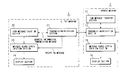
Fig. 1 is a functional block diagram depicting the general
configuration of the server machine 1 and the client machine 2
used for this system. The server machine l comprises a message
transfer section ll which transfers a received message when
necessary, a transmission/reception section 12 for communicating
with the client machine, a message board screen creation section
13 which creates a screen of the message boax:d based on the received
message, and a display section 14 which x-eceives the output of
the screen creation section 13 and displays lthe screen. The client
machine 2 comprises a transmission/reception section 21 for
communicating with the server machine, a message creation section
22 which creates a transmission message, a message board screen
creation section 23 which receives the transmission message from
the message creation section 22, receives the reception message
from the transmission/reception section 21, and displays these
messages on the message board, and a display section 24 which
receives the output of the screen creation section 23 and displays
it on the screen..
Fig. 2 is a functional block diagram of a wireless gateway
3 which performs 2-way conversion of the interface for a personal
computer and the interface for the Internet portable telephone
3o to be used for this system. The wireless gateway is an interface
conversion device for the Internet portable telephone which
performs wireless communication. This device comprises a
transmission/reception section 31 for communicating with the
11
CA 02337663 2001-02-22
server machine 1, a transmission/reception section 32 for
communicating with the protocol conversion server of the
communication carrier, and a conversion section 32 which performs
2-way conversion of the interface for a personal computer and the
interface for the Internet portable telephone. The conversion
section 32 converts the display screen interface for a personal
computer to the interface for the Internet portable telephone or
vice versa. Compared with the display capability of the personal
computer, the display capability of the Internet portable telephone
. is much less, so necessary information is processed according to
the display capability of the Internet portable telephone. For
example, the graphic displays of "rice ba7_1 icon" and "sandwich
icon" are replaced with the characters "rice: ball" and "sandwich" .
Therefore the wireless gateway 3 comprises. a data base, which is
not illustrated, for storing information on the correspondence
between graphics and characters . Or this data on correspondence
is received from the server 1. Another example is that the current
position displayed on a map is converted to longitude/latitude
information and/or the address display information by characters.
In this case, a database for storing the correspondence between
positions on maps, and longitude/latitude information and/or
address display information is provided .in advance.
Fig. 3 is a conceptual diagram depicting the general
configuration of this system. The client 2 can access the server
1 via the Internet/intranet 4 . The server 1 stores the application
software (,lava applet ) for this system in iehe external memory in
advance. When the client accesses the server, the application
software~for the client is downloaded and this system becomes
available. The Internet portable telephone 6 (or beeper), on the
other hand, accesses the wireless gateway 3 via the protocol
conversion server 5, which is equipment of the communication
carrier, and also accesses the server 1.
12
CA 02337663 2001-02-22
A method of accessing content on the Internet from each
portable telephone ( including PHS ) will now be briefly described.
At the moment, the following four typEa of methods are used.
All of these services are accessed by HTT~P on the Internet, but
information sent via HTTP is described differently.
(1) [i-Mode system] described in i-Mode supported HTML
(2) [J-SkyWeb system] described in J-SkyWeb supported HTML
(3) [WAP/HDML system ] described in HDML
(4) [P mail DX system] described in P mail DX text
The i-Mode system and the J-SkyWeb system can be described
in HTML just like a regular web page, but the type of tags used
in HTML are limited. Therefore the web page described in these
systems can be accessed by the browser running on a regular personal
computer. The WAP/HDML system and P mail DX system are similar
to HTML since tags are embedded in the tE:xt, but uses a unique
description method designed especially for portable telephone
services.
2o All the above four systems can implement the text-based
message system of the present embodiment since these systems can
use HTTP as the transfer protocol (that is, ;service can be provided
by Java Servlets), and have little difference in functions.
Fig. 4 shows an exchange of messages between the server 1,
the client 2 and the Internet portable telephones 6a and 6b. When
the client 2 creates a message, the message M1 is transmitted to
the server 1, and is also displayed on the self screen. The server
1 identifies the destination of the received message M1, and
3o transmits it to the destination-Internet portable telephone 6a
(M2 to M4). When the Internet portable telephone 6a creates a
reply message, the replay message is transmitted to the client
2 (M5 to M8 ) . If the message is a broadcast message, the message
13
CA 02337663 2001-02-22
M11, transmitted from the Internet portable telephone 6a, is also
transmitted to all the other clients 2 and 6b (M12 to M17). In
this way, message communication via the server 1 is possible among
all the clients 2 and 6a and 6b.
Fig. 5 shows the processing flow in the client 2 which transmits
a message. When the user clicks a message icon ( S1 ) , a message
creation dialog is displayed. The user can create an arbitrary
message here (S2). The user drags and drops the icon on to an
arbitrary position of the message board (S3). The message can
be transmitted by this operation. The client displays the message
on the self screen (S4), and also transmits the message (S5).
The screens shown in Fig. 10 ( a ) and ( b ) , for example, are
displayed on the display screen of the Internet portable telephone
6 . Fig. 10 ( a ) shows a screen when the user has accessed the server
1. The menu 1 is for creating a new message to transmit. The
menus 2 and 3 are for reading the message 1 o:r 2, which is addressed
to the user or is for broadcasting. Fig. 10 (b) shows a screen
when the menu 1 is selected and the message l is displayed.
The processing flow in the Internet poi: table telephone 6 will
now be described with reference to the flow chart in Fig. 5. At
first, the user selects menu 1 "new message" ( S1 ) , then the message
creation dialog is displayed . The user can create an arbitrary
message here (S2). The user specifies the transmission
destination of the created message ( S3 ) . At: this time, the message
can be transmitted without any relationship to an existent message,
or can be transmitted in association with an existent message (e. g.
as a reply to a message). The Internet portable telephone 6
displays a message on the self screen (S4), and also transmits
the message (S5).
14
CA 02337663 2001-02-22
Fig. 6 shows a processing flow in the server. When the server
receives a message ( S10 ) , the server opens the message ( S11 ) , and
stores it to the self memory. And the server transfers the message
to a predetermined destination (S12).
Fig. 7 shows a processing flow in the client which receives
a message. When the client receives a message from the server
(S20 ) , the client opens the message ( S21 ) , and displays the message
on the message board thereof . In the screen in Fig. 10, for example,
the Internet portable telephone 6 creates a new menu 4 and displays
the menu.
By the processings in Fig. 5 to Fig. 7, the message written
to a client is immediately reflected on the screens of the other
clients. ~n this way, the transmission/i:eception of a message
between arbitrary clients can be synchronously known in real-time.
Management is easy since all the information is collected in the
server.
Fig. 8 shows a security processing flow of the server. When
an access request for an opened message ( ic;on ) is received ( S31 ) ,
the server checks whether the requesting user has the right ( S32 ) ,
permits access if the user has the right (S33), and rejects the
request if not (S43). Similar processing is also executed when
moving a message (that is, changing the transmission destination
address ) , editing a message, and deleting a message are requested
(S34 - S42 ) . For example, if this system is a bulletin board which
anyone can access, accessing and moving are permitted to anyone.
But editing and deleting are permitted only to the user who
3o transmitted the message or to the administrator.
Fig. 9 shows an example of a messagEa board screen of this
system. The message board 30 and examples of the message, 31 and
CA 02337663 2001-02-22
32, to be displayed here, are displayed on 'the screen. The icons
33, 34 and 35 at the bottom of the screen are a message creation
icon 33, GO icon 34, which creating a link t:o a related home page,
and a trash can icon 35, which deletes a message respectively.
The icons 31a and 31b indicate messages from clients of a personal
computer, and icons 32a and 32c are messages from Internet portable
telephones . By changing the type of icon, a:message from a personal
computer client and a message from an Internet portable telephone
can be easily identified on the message board 30. The server 1
l0 selects a type of icon by checking whether the message is from
the wireless gateway 3.
Based on this drawing, the operation method of this system
will be described. To transmit a message, the icon 33 is clicked
and a message is created. And the icon 33 is dragged and dropped
on to an arbitrary position of the message board 30. Then the
message is opened and can be read as seen in 31 and 32. The status
of this screen is the same for all clients, as the flow in Fig.
4 shows. Therefore, the user can read all the messages on the
2o screen on the self client machine. Unlil~;e the broadcasting of
conventional electronic mail, this system can send a message to
all participant users without specifyingv destinations. Also,
operation using icons is very intuitive a:nd easy to understand,
and is very easy to use.
The case of the Internet portable telephone will now be
described. When the Internet portable telephone 6 accesses the
server 1 via the protocol conversion server 5 and the wireless
gateway 4 , the screen shown in Fig . 10 ( a ) , for example, is displayed,
3o where messages on the message board can be known. The user can
read any message in a range permitted byythe terms of security:
16
- ~ CA 02337663 2001-02-22
Security problems are not a very serious issue on this-message
board. Here any user can create, paste or delete a message. Of
course the level of security canbe increased so that only a specified
individual ( e. g. administrator ) can move and delete a message ( see
Fig. 8).
Embodiment 2
The relationship between messages may be indicated on the
message board. For example, as Fig. 11 shows, lines are drawn
i0 between the response to a message, and a plurality of related
messages are displayed as a group. Also, as. Fig. 11 shows, symbols
Al; A2, . . . may be added to the branches of a:message. By referring
to these symbols, a desired message-can be directly opened. Such
a reference method is particularly useful with the Internet
is portable telephone. On the display of the Internet portable
telephone, messages are displayed in a hierarchical structure,
where it takes time to reach the message to be read if the message
is deep in the hierarchy. If reference symbols are added, as shown
in Fig. 11, then the message can be directly selected and read
2o using a symbol as a search key.
Also the URL or telephone number of th.e user who transmitted
the message may be displayed with the icon of the message, as Fig.
12 shows . By this display, the user who transmitted of the message
25 can be specified. The telephone call may b~e made to the telephone
number by double clicking the icon.
Embodiment 3
The above description concerned the message system, but the
30 present invention may be applied to a system which includes the
Internet portable telephone. By the server 1 and the wireless
gateway 3, data format conversion, real-time update control of
messages and data exchange with another database are possible,
17
~
CA 02337663 2001-02-22
among not only a server and clients connected to the Internet but
also with Internet portable telephones. Using this function,
various applications can be provided. For example, a
communication board for text messages and image messages, such
games as character development games, match games ( Igo, Shogi) ,
and such local information services as convenience store special
sale information and cosmetics special sale information, can be
provided.
to Fig. 13 is an example of a local information service according
to embodiment 3. The client 2 at the store' accesses the special
sale information board on the server 1, and writes the special
sales information. Then such information as "sandwiches: 50~ off"
or "rice balls: 30~ off" is displayed on the web browser screen.
i5 By this, information can be transmitted i.n real-time. The web
browser screen is converted to the display :format of the Internet
portable telephone by the wireless gateway 3. The user accesses
the content of the special sales information and refers to the
special sales information by the Internet portable telephone. At
2o this time, the areas which can be accessed may be limited in order
to obtain information on the closest locai~ion all the time. On
the display screen of the Internet portable telephone, such
information as "xxx store special sales information" , "sandwiches
50~ off" or "rice balls: 30$ off" is displayed.
Fig. 14 is an example of a communication board with positional
information management functions in accordance with the third
embodiment. The client 2 accesses the~ma,p and positional
information board on the server 1, and writes or refers to a message
3o and image. Then the positional information on the map is displayed
on the web browses screen. The web browses screen is converted
to the display format of the Internet portable telephone by the
wireless gateway 3. Since the Internet pori~able telephone cannot~
18
~
CA 02337663 2001-02-22
handle image information very well, the wireless gateway 3 converts
the positional information on the screen to longitude/latitude
and/or address information by characters. The Internet portable
telephone refers to this information.
Various other applications are possible. This invention
allows a message exchange between the Internet portable telephone
and a regular personal computer via the Internet . Also according
to the present invention, messages can be easily exchanged among
to a plurality of users; unlike conventional electronic mail. This
is possible because the present invention comprises the server
1 and the wireless gateway 3.
Embodiment 4
In the present system/method described above, an image
prepared by the user can be included in the icon. The system/method
for this will now be described.
Fig. 15 is a block diagram depicting a system in accordance
with the fourth embodiment. Fig. 15 corresponds to Fig. 3, which
was described above. In Fig. 15, the sy:~tem further comprises
the image server 5 and the image memory 5a, the image memory icons
5b, and the image memory for portable telephone 5c, which are
connected to the image server 5 . The image server 5 receives image
data along with a message or by itself from t:he client 2, and stores
this image data to the image memory 5a. The image server 5 converts
the received image data to the image for icons and the image for
a portable telephone, and stores these to the image memory for
icons 5b and memory for a portable telephone 5c respectively.
The processing procedure of the syst~em/method according to
the fourth embodiment will now be described with reference to the
flow chart in Fig. 16.
19
~
' CA 02337663 2001-02-22
A message and image data are transmitaed from the client 2
to the server 1 (S50). In the server 1, the message and image
data are separated (S51). The separated message is distributed
to each client, as described above ( see Fig. 4 ) . In the present
embodiment, however, not only the message but also the image data
and/or the pointer (e.g. URL), which indicates the position of
the image for icons and the image for a porltable telephone on the
network, are transmitted to each client. In other words, the
pointer of the image is generated (S52 ) , a:nd the message and the
pointer of the image are transmitted to the client 2a and the Internet
portable telephone 6 (S53). It is predetermined that the image
data will be stored to the image server 5, and the pointer is the
URI~ of the image server 5. The image data is specified by the
name or address of the transmitter or title, so the URL includes
the name and address of the transmitter and title, for example.
The pointer of the image includes information indicating the
storage location of the original image, information indicating
the storage location of the image for icons, and information
indicating the storage location of the image for a portable
telephone. This information is not always transmitted together.
For example, only the storage location of the image for a portable
telephone may be transmitted to a portable telephone.
The image data is transmitted from the server 1 to the image
server 5 (S54 ) . The image server 5 stores t:he received image data
to the image memory 5a, generates the image data for the icons
and image data for a portable telephone from the received image
data (555, S56), and stores the image data to the image memory
for icons 5b and the image memory for a :portable telephone 5c
respectively. The image data for icons is incorporated into the
icon 40 of the message, as shown in Fig. 17. The image for icons
is generally smaller than the originalmessaqe. So it is preferable
_ 20
CA 02337663 2001-02-22
to decrease the size of the original images data by lowering the
resolution of the data and increasing the connpression rate of image
compression. The size (number of pixels) of the image data for
icons is determined depending on the relationship between the size
of the icon displayed on the screen and the display capability
of the screen. The image data for a portable telephone is generally
smaller than the original image as well. So, just like the case
of icons, the size of the data is decrea~~ed. The size (number
of pixels ) of the image data for a portable telephone is determined
1o depending on the display capability of the screen of the portable
'telephone. Also, depending on the color display capability of
the screen of the portable telephone, the color data of the image
is compressed . For example, if the screen of the portable telephone
is monochrome, color information is unnecessary.
1S
When the message and the pointer of they image are transmitted
to the client 2a, the client 2a requests i~he image for icons to
the image server 5 ( S57 ) . The client 2a accesses the image server
5 using the pointer of the image received i.n 553. Then the image
20 server 5 transmits the image for icons to the client 2a (S58).
And the client 2a incorporates the received image for icons to
the icon 40.
To obtain the original image, the user clicks on the "Download"
25 button shown in Fig. 17. Then the client :2a transmits the image
request to the image server 5 ( S59 ) , and the image server 5 transmits
the original image to the client 2a (S60). And the client 2a
displays the received image and stores the :i.mage to the local hard
disk.
When the message and the image pointer are displayed on the
Internet portable telephone 6, the Internet portable telephone
6 requests the image for portable telephone to the image server
21
CA 02337663 2001-02-22
(S61). The image server 5 transmits the image for portable
telephone to the Internet portable telephone 6 ( S62 ) . Then the
Internet portable telephone 6 displays the received image on its
screen.
5
Fig. 17 shows an example of the screen of the client 2 in
the fourth embodiment. The icon 40 of the message is displayed,
where the icon 40 includes the image 40a, and also includes the
display 40b to identify the transmitter, a message button 40c and
to the download button 4Od. The message can be received by clicking
the message button 40c. The original image can be downloaded by
clicking the download button 4Od.
The message transmission procedure will now be briefly
described. At first the message creation icon 33 is clicked. Then
the dialog box for inputting an image is displayed, and the message
is input there. To transmit an image, the Lmage button is clicked
in order to display the dialog box for inputting an image. The
image file is selected in this dialog box. When the dialog box
is closed, the icon is displayed, so this icon. is dragged and dropped
onto a predetermined location. The image included in the icon
may be created by the client 2, who is the transmitter, or may
be obtained from the image server 5 using the .image pointer received
from the server 1.
According to the system/method of the: fourth embodiment of
the present invention, an image can be transmitted along with a
message. Since the image to be transmitted ~.s included in the
icon, the receiver can know the content intuitively. Unlike
conventional electronic mail, messages can be easily exchanged
among a plurality of users. Operation is also easy by using a
drag and drop operation of icons.
22 _ _ .
' CA 02337663 2001-02-22
The present invention is not restricted to the above
embodiments, and various modifications are possible within a scope
of the invention stated in the Claims, and, needless to say, these
variant forms are included in the scope of the present invention.
In this description, means does not always mean a physical
means, but includes the case when the functions of each means are
implemented by software. The functions of a means may be
implemented by two or more physical means., or the functions of
1o two or more means may be implemented by one physical means.
23