Sélection de la langue

Search

Sommaire du brevet 2337720 

Énoncé de désistement de responsabilité concernant l'information provenant de tiers

Une partie des informations de ce site Web a été fournie par des sources externes. Le gouvernement du Canada n'assume aucune responsabilité concernant la précision, l'actualité ou la fiabilité des informations fournies par les sources externes. Les utilisateurs qui désirent employer cette information devraient consulter directement la source des informations. Le contenu fourni par les sources externes n'est pas assujetti aux exigences sur les langues officielles, la protection des renseignements personnels et l'accessibilité.

Disponibilité de l'Abrégé et des Revendications

L'apparition de différences dans le texte et l'image des Revendications et de l'Abrégé dépend du moment auquel le document est publié. Les textes des Revendications et de l'Abrégé sont affichés :

  • lorsque la demande peut être examinée par le public;
  • lorsque le brevet est émis (délivrance).
(12) Brevet: (11) CA 2337720
(54) Titre français: BARRIERE EN PLASTIQUE LAMINE
(54) Titre anglais: LAMINATED PLASTIC BARRIER FENCE
Statut: Périmé et au-delà du délai pour l’annulation
Données bibliographiques
(51) Classification internationale des brevets (CIB):
  • E04H 17/00 (2006.01)
(72) Inventeurs :
  • JOLLIFFE, WAYNE HERBERT (Canada)
(73) Titulaires :
  • WAYNE HERBERT JOLLIFFE
(71) Demandeurs :
  • WAYNE HERBERT JOLLIFFE (Canada)
(74) Agent:
(74) Co-agent:
(45) Délivré: 2003-08-12
(22) Date de dépôt: 2001-02-21
(41) Mise à la disponibilité du public: 2001-08-22
Requête d'examen: 2002-04-05
Licence disponible: S.O.
Cédé au domaine public: S.O.
(25) Langue des documents déposés: Anglais

Traité de coopération en matière de brevets (PCT): Non

(30) Données de priorité de la demande:
Numéro de la demande Pays / territoire Date
60/183,801 (Etats-Unis d'Amérique) 2000-02-22

Abrégés

Abrégé anglais


A laminated plastic barrier type fence encapsulates a printed
message or sign. The plastic fence is laminated. A message or sign
which is printed on a portion of one side of a first sheet of plastic
sheeting material. They first sheet is then laminated to a second sheet of
plastic sheeting material. A regular array of apertures is made in the
laminated sheet to either side of the printing.

Revendications

Note : Les revendications sont présentées dans la langue officielle dans laquelle elles ont été soumises.


11
CLAIMS:
1. A laminated plastic fence comprising a lamination of at least two sheets of
plastic
sheeting material having printed subject matter on a portion of a side of at
least
one of the sheets and having apertures through a remaining portion of the
laminated plastic fence.
2. The laminated plastic fence according to claim 1, wherein a side of a sheet
having
printed subject matter thereon is laminated to a side of another of the
sheets.
3. The laminated plastic fence according to claim 2, wherein the printed
subject
matter is encapsulated between the sheets.
4. The laminated plastic fence according to any one of claims 1 to 3, wherein
the
fence is laminated in a lamination process comprising application of an
adhesive
and heat.
5. The laminated plastic fence according to claim 4, wherein the lamination
process
comprises application of pressure.
6. The laminated plastic fence according to any one of claims 1 to 5, wherein
a sheet
is transparent.
7. The laminated plastic fence according to any one of claims 1 to 6, wherein
a sheet
is not transparent.
8. The laminated plastic fence according to any one of claims 1 to 7, wherein
the
sheet or sheets having printed subject matter thereon is/are transparent.
9. The laminated plastic fence according to any one of claims 1 to 8, wherein
a
portion of the fence having printed subject matter thereon is continuous along
a
length of the fence.

12
10. The laminated plastic fence according to any one of claims 1 to 9, wherein
a
remaining portion having apertures is adjacent the portion with the printed
subject
matter.
11. The laminated plastic fence according to claim 10, wherein there are two
remaining portions.
12. The laminated plastic fence according to claim 1, which is a lamination of
two
sheets of plastic sheeting material.
13. The laminated plastic fence according to claim 12, wherein the printed
subject
matter is on a portion of one side of one of the sheets.
14. The laminated plastic fence according to claim 13, wherein the side of the
sheet
having the printed subject matter thereon is laminated to a side of the other
sheet
such that the printed subject matter is encapsulated between the sheets.
15. The laminated plastic fence according to claims 13 or 14, wherein the
sheet
having the subject matter printed thereon is transparent.
16. The laminated plastic fence according to claim 15, wherein the other sheet
is not
transparent.
17. The laminated plastic fence according to any one of claims 13 to 16,
wherein the
sheet having subject matter printed thereon is thinner than the other sheet.
18. The laminated plastic fence according to any one of claims 12 to 17,
wherein a
portion of the fence having printed subject matter thereon is continuous along
a
length of the fence.
19. The laminated plastic fence according to any one of claims 12 to 18,
wherein a
remaining portion having apertures is adjacent the portion with the printed
subject
matter.

13
20. The laminated plastic fence according to claim 19, wherein there are two
remaining portions.
21. The laminated plastic fence according to any one of claims 12 to 20,
wherein the
fence is laminated in a lamination process comprising application of an
adhesive
and heat
22. The laminated plastic fence according to claim 21, wherein the lamination
process
comprises application of pressure.
23. The laminated plastic fence according to claim 1, which is a lamination of
a
backing sheet of plastic sheeting material between two exterior sheets of
plastic
sheeting material.
24. The laminated plastic fence according to claim 23, wherein the subject
matter is
printed on a portion of one side of an exterior sheet.
25. The laminated plastic fence according to claim 24, wherein the backing
sheet is
laminated to the side of the exterior sheet having printed subject matter
thereon
such that the subject matter printed on the exterior sheet is encapsulated
between
the exterior sheet and the backing sheet.
26. The laminated plastic fence according to claims 24 or 25, wherein the
exterior
sheet is transparent.
27. The laminated plastic fence according to any one of claims 24 to 26,
wherein the
backing sheet is not transparent.
28. The laminated plastic fence according to any one of claims 24 to 27,
wherein the
exterior sheet is thinner than the backing sheet.
29. The laminated plastic fence according to claim 23, wherein the subject
matter is
printed on a portion of one side of each of the exterior sheets.

14
30. The laminated plastic fence according to claim 29, wherein the backing
sheet is
laminated to the side of the exterior sheets having printed subject matter
thereon
such that the subject matter printed on each exterior sheet is encapsulated
between the respective exterior sheet and the backing sheet.
31. The laminated plastic fence according to claims 29 or 30, wherein the
exterior
sheets are transparent
32. The laminated plastic fence according to any one of claims 29 to 31,
wherein the
backing sheet is not transparent.
33. The laminated plastic fence according to any one of claims 29 to 32,
wherein the
exterior sheets are thinner than the backing sheet.
34. The laminated plastic fence according to any one of claims 23 to 33,
wherein a
portion of the fence having printed subject matter thereon is continuous along
a
length of the fence.
35. The laminated plastic fence according to any one of claims 23 to 34,
wherein a
remaining portion having apertures is adjacent the portion with the printed
subject
matter.
36. The laminated plastic fence according to claim 35, wherein there are two
remaining portions.
37. The laminated plastic fence according to any one of claims 23 to 36,
wherein the
fence is laminated in a lamination process comprising application of an
adhesive
and heat.
38. The laminated plastic fence according to claim 37, wherein the lamination
process
comprises application of pressure.
39. A method of making a plastic fence having printed subject matter
comprising the
steps of:

15
(a) printing subject matter on a portion of a side of a first sheet of plastic
sheeting material;
(b) laminating the first sheet of plastic sheeting material to a second sheet
of
plastic sheeting material to produce a laminated sheet; and,
(c) cutting an array of apertures through a remaining portion of the laminated
sheet adjacent the printed portion.
40. The method according to claim 39, wherein the first sheet is transparent.
41. The method according to claim 40, wherein a side of the first sheet having
the
printed subject matter is laminated to a side of the second sheet to
encapsulate
the printed subject matter between the first and second sheets.
42. The method according to any one of claims 39 to 41, wherein the second
sheet is
not transparent.
43. The method according to any one of claims 39 to 42, wherein a third sheet
of
plastic sheeting material having printed subject matter on a portion of a side
thereof is laminated to the second sheet.
44. The method according to claim 43, wherein a side of the third sheet having
the
printed subject matter is laminated to a side of the second sheet opposite the
first
sheet to encapsulate the printed subject matter between the third and second
sheets.
45. The method according to any one of claims 39 to 44, wherein the array of
apertures is cut using a die.
46. The method according to any one of claims 39 to 45, wherein the laminating
step
comprises application of an adhesive and heat.
47. The method according to claim 46, wherein the laminating step comprises
application of pressure.

Description

Note : Les descriptions sont présentées dans la langue officielle dans laquelle elles ont été soumises.


CA 02337720 2001-02-21
TITLE: LAMINATED PLASTIC BARRIER FENCE
INVENTOR: WAYNE HERBERT JOLLIFFE
BACKGROUND OF THE INVENTION
The invention relates to improvements in a plastic barrier type
fence and a method of making such a fence. In another embodiment, the
invention relates to a laminated plastic barrier type fence which physically
incorporates and displays a message or sign comprising text, graphics,
pictures or the like.
Plastic barrier type fencing is known and is typically used, by way
of example, in the vicinity of construction sites ar sporting events to
demark protected or designated areas from ingress by members of the
public. The plastic fencing may be manufactured from a number of
different UV stabilized engineered polymers including, for example, high
density polyethylene. 'The fencing is typically manufactured in thousand
foot lengths and various heights, and may be made in any colour. The
fencing is available in rolls making it highly portable and easy to install.
This type of fencing functions extremely well as a physical and visible
barrier to control and direct crowds.

' CA 02337720 2001-02-21
One disadvantage associated with plastic barrier type fencing is the
difficulty of attaching a message or sign to the plastic fence. The
presentation of printed subject matter on a plastic fence is considered
highly desirable in terms of increasing its utility and versatility. While it
is
obvious, for example, to attach a banner or the like bearing a message to
the plastic fence by means of ties, this is not very satisfactory from either
a functional or esthetic: point of view. The banner attached in the manner
aforesaid never appears to be properly displayed and is susceptible of
being torn and damaged during installation, use or storage.
One inherent problem with this type of fencing is the so-called "sail
effect"meaning that the action of places aerodynamic load
the wind an
on fence tending 1:o dislodge mooringsor attachments on
the it from its
the ground. The fact 'that plastic fencing is provided with a regular array
of apertures or perforations minimizes this effect. However, a banner
bearing the message or sign cannot be provided with a regular array of I
apertures without in effect destroying the presentation. Accordingly, the
use of solid banners increases and multiplies the "sail effect" to the
detriment of both the fence and the fence installation. Another
disadvantage of attaching banners to a plastic fence in the manner

~ CA 02337720 2001-02-21
3
described is that, the banner cannot be re-used after storage as roll-up
storage of the fence may damage the banner.
It is an object of the present invention to provide a method of I
manufacturing a plastic fence having printed subject matter comprising at
least the following steps. A first step of printing a message or sign on
one side of a first sheet of plastic sheeting material. A second step of
laminating the first shE;et of plastic sheeting material to a second sheet of
plastic sheeting material. A third step of cutting an array of apertures in
the laminated sheet to either side of the printed message or sign.
SUMMARY OF THE INVENTION
With the forgoing in mind it is a principal object of this invention to
provide a portable, highly visible, re-useable, high strength, UV stabilized,
plastic barrier type fence which physically incorporates a printed message
or sign of any kind or clescription. The prime utility or feature of the
fence according to this invention is the improved ability to display a
message or sign to the general public in the vicinity of the fence. The
invention does not actively concern itself with the actual strength of the
fence in terms of its ability to physically restrain a person or crowd.

CA 02337720 2001-02-21
BRIEF DESCRIPTION OF THE DRAWING
Figure 1 is a side view of a section of plastic fence made according to
this invention.
Figure 2 is a laminated cross-section of one embodiment of the
plastic fence.
Figure 3 is another laminated cross-section of another embodiment of
the plastic: fence. ',
DETAILED DESCRIPTION OF THE PREFERRED EMBODIMENT
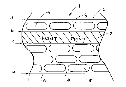
Referring in general to the drawings and initially to Figure 1, a
typical section of plastic fence made according to this invention is shown.
The fence (1 ) consists of a laminated plastic sheet having a solid
bandwidth region (2) having a width be within the confines of which the
message or sign is displayed which is indicated in the Figure and by way
of example, using the word PRINT. The remainder of fence to either side
of the bandwidth portion 2 is comprised of perforated or apertured
regions 3 and 4 having widths ab and cd respectively. The perforations
or apertures 5 are those typically made in plastic fencing and are made in

CA 02337720 2001-02-21
S
any repeating pattern. A preferred method of manufacturing the plastic
fence according to this invention incorporating a message or sign is now
described.
Firstly, the message or sign intended for display is printed on thin
transparent plastic sheeting material using known methods of printing
which will be hereinafter referred to as the exterior sheet. Typically, such
sheeting material is manufactured in rolls having different thicknesses and
widths. In accordance with one embodiment, a roll of plastic sheeting
material having an approximate thickness of 3 to 4 mils and an
approximate width of ~.8 inches is used for printing. As explained,
although the message or sign may be printed anywhere on the exterior
sheet, it is preferably printed within the confines of the bandwidth 2
leaving the remainder of the exterior sheet transparent.
The printed message or sign typically consists of text, graphics,
solid colours or the like all of which subject matter is intended to be
brought to the attention of the general public in the vicinity of the fence.
In certain circumstances, a message or sign need not be printed on the
exterior sheet and may instead consist of any particular distinctive feature
inherent to the exterior sheet. For example, the exterior sheet may

CA 02337720 2001-02-21
6
consist of a thin sheet of Milar~ reflective film and its use in the manner
hereinafter described will give the fence reflective properties.
It is also important to have regard to the manner in which the
message or sign is printed on one of the sides of the exterior sheet. If for
example, it is desired to encapsulate the printed subject matter within the
fence, the subject matter must be reversed printed on one side of the
exterior sheet so that it may only be correctly understood and read when
viewed from the other side of the sheet. According to this aspect of the
invention, the side of the exterior sheet on which the message or sign has
been printed will be laminated as hereinafter described with the
consequence that the print will be protected by the width of the exterior
sheet overlying the message or sign.
The bandwidth for the printed subject matter is preferably between
12 and 16 inches and may be positioned anywhere between the width
extremities 6 of the exterior sheet as preference suits. Usually, the
printed message will bE~ located near the top of the fence so as to be
more visible to the general public. Because the exterior sheet is
transparent, the reverse printed subject matter on one side thereof may
be viewed and correctly understood by looking through the other side of

CA 02337720 2001-02-21
7
the sheet. In this way, having regard to the lamination steps hereinafter
described, the print is encapsulated and protected from damage or
scratching by means of a plastic covering. The message or sign, of
course, need not be reverse printing on the exterior sheet for
encapsulation in all cases to obtain the benefits of the invention.
Following the printing step, the exterior sheet is now laminated to
a second preferably thicker backing sheet (7) of plastic sheeting material.
Referring to Figure 2, the exterior sheet 7 is laminated to the backing
sheet 8 which is also approximately 48 inches in width and approximately
8 to 10 mil in thickness. In the embodiment shown, it can be seen that
the side 9 of the exterior sheet 6 on which the subject matter has been
printed is laminated to one side of the backing sheet. In this way, the
printed subject matter is encapsulated within the plastic sheets and
protected from damage on both sides by the width of the layers of the
plastic sheeting material. Since the backing sheet is not transparent, the
message or sign in the embodiment shown will be visible to only one side
of the fence and may k>e correctly understood by virtue of having been
reversed printed as described.

CA 02337720 2001-02-21
The lamination process employed is one involving the application of
adhesive to one or both surfaces of the sheets being laminated. The final
lamination step is completed by means of the application of heat and
pressure in the usual way. This lamination step produces the laminated
fence material having a thickness of approximately 14 to 18 mils having
the message or sign in encapsulated therein.
In yet another embodiment of the invention shown in Figure 3, a
further lamination step is performed wherein a second exterior sheet 7(a)
prepared identically to the first mentioned exterior sheet 7 is laminated to
the other side of the backing sheet 8 in the same identical way. This
lamination variation produces a fence having a visible message or sign
which is visible on either side of the fence. Yet a further variation of the
invention may include laminating the laminated sheet shown in Figure 2
to one identical to it along surface 10 resulting in thicker and stronger
fence with a visible sign or message sign on each side thereof.
The lamination step or steps described above may result in flaws in
adhesion in the vicinity of the outside edges of the laminated sheets. A
standard trimming step may be required to eliminate these flaws.

CA 02337720 2001-02-21
The final step in the manufacturing process involves providing the
plastic fence with the appearance and functionality of a fence by
providing the laminated sheet with apertures or perforations (5) on either
side of the bandwidth be bearing the printed subject matter. This is also
preferable from the point of view of minimizing the sail effect. The
apertures are formed by passing the laminated sheets) through a die
cutting machine where the cutting dies are aligned and positioned with
reference to the laminated sheet to either side of the bandwidth bc. The
laminated sheets are then fed or indexed through the die cutting machine
to make the aperture:.. Any type or arrangement of apertures may be
provided bearing in mind that the objective is one of maximizing the size
of the apertures without sacrificing the strength of the fence material.
The plastic material removed by the die may be recycled and used, for
example, to make plastic posts to which the fence may be attached as
described hereinafter.
The fence made according to this invention may be erected using
T-posts inserted and fixed in the ground. The T-post has a flat side
against which the plastic fence material is placed in abutment.
Thereafter, a wood slat is placed and aligned on the opposite side of the
flat portion of the T-bar sandwiching the barrier fence therebetween.

CA 02337720 2002-07-17
Ties or plastic cables can be used to secure the slat to the T'-post thereby
securing the
fence. To connect adjacent fencing sections at their ends the fence portions
may be
overlapped and a wooden slat weaved through the apertures in the fence. These
methods of attaching the barrier fence will work extremely well for the
purpose of
5 equivalent alternations and modifications, and is limited only by the scope
of the claims.
From the forgoing, it will be seen that this invention is one well adapted to
attain all
the ends and objects hereinabove set forth together with other advantages
which are
obvious and which are inherent to the structure.
Since many possible embodiments may be made of the invention without
10 departing from the scope of the thereof, it is to be understood that all
matter herein set
forth or shown in the accompanying drawings is to be interpreted as
illustrative and not in
a limiting sense.
Although the invention has been shown and described with respect to certain
preferred embodiments, it is obvious that the equivalent alterations and
modifications will
occur to others skilled in the art upon the reading and understanding of the
specification.
The present invention includes all such equivalent alternations and
modifications, and is
limited only by the scope of the claims.

Dessin représentatif
Une figure unique qui représente un dessin illustrant l'invention.
États administratifs

2024-08-01 : Dans le cadre de la transition vers les Brevets de nouvelle génération (BNG), la base de données sur les brevets canadiens (BDBC) contient désormais un Historique d'événement plus détaillé, qui reproduit le Journal des événements de notre nouvelle solution interne.

Veuillez noter que les événements débutant par « Inactive : » se réfèrent à des événements qui ne sont plus utilisés dans notre nouvelle solution interne.

Pour une meilleure compréhension de l'état de la demande ou brevet qui figure sur cette page, la rubrique Mise en garde , et les descriptions de Brevet , Historique d'événement , Taxes périodiques et Historique des paiements devraient être consultées.

Historique d'événement

Description Date
Le délai pour l'annulation est expiré 2010-02-22
Inactive : Demande ad hoc documentée 2009-11-27
Lettre envoyée 2009-02-23
Inactive : Lettre officielle 2006-11-30
Inactive : Lettre officielle 2006-02-27
Inactive : Paiement - Taxe insuffisante 2006-02-16
Accordé par délivrance 2003-08-12
Inactive : Page couverture publiée 2003-08-11
Préoctroi 2003-05-27
Inactive : Taxe finale reçue 2003-05-27
Un avis d'acceptation est envoyé 2003-05-15
Lettre envoyée 2003-05-15
Un avis d'acceptation est envoyé 2003-05-15
Inactive : Approuvée aux fins d'acceptation (AFA) 2003-05-01
Modification reçue - modification volontaire 2003-03-14
Inactive : Dem. de l'examinateur par.30(2) Règles 2002-10-03
Modification reçue - modification volontaire 2002-07-17
Inactive : Dem. de l'examinateur par.30(2) Règles 2002-05-22
Lettre envoyée 2002-04-25
Avancement de l'examen jugé conforme - alinéa 84(1)a) des Règles sur les brevets 2002-04-25
Inactive : Grandeur de l'entité changée 2002-04-25
Requête d'examen reçue 2002-04-05
Inactive : Avancement d'examen (OS) 2002-04-05
Exigences pour une requête d'examen - jugée conforme 2002-04-05
Inactive : Taxe de devanc. d'examen (OS) traitée 2002-04-05
Toutes les exigences pour l'examen - jugée conforme 2002-04-05
Accessibilité au public anticipée demandée 2002-04-05
Demande publiée (accessible au public) 2001-08-22
Inactive : Page couverture publiée 2001-08-21
Inactive : CIB en 1re position 2001-05-01
Inactive : Certificat de dépôt - Sans RE (Anglais) 2001-03-23
Exigences de dépôt - jugé conforme 2001-03-23
Demande reçue - nationale ordinaire 2001-03-23

Historique d'abandonnement

Il n'y a pas d'historique d'abandonnement

Taxes périodiques

Le dernier paiement a été reçu le 2003-02-05

Avis : Si le paiement en totalité n'a pas été reçu au plus tard à la date indiquée, une taxe supplémentaire peut être imposée, soit une des taxes suivantes :

  • taxe de rétablissement ;
  • taxe pour paiement en souffrance ; ou
  • taxe additionnelle pour le renversement d'une péremption réputée.

Veuillez vous référer à la page web des taxes sur les brevets de l'OPIC pour voir tous les montants actuels des taxes.

Historique des taxes

Type de taxes Anniversaire Échéance Date payée
Taxe pour le dépôt - petite 2001-02-21
Requête d'examen - générale 2002-04-05
Avancement de l'examen 2002-04-05
TM (demande, 2e anniv.) - générale 02 2003-02-21 2003-02-05
Taxe finale - générale 2003-05-27
TM (brevet, 3e anniv.) - générale 2004-02-23 2004-02-05
TM (brevet, 4e anniv.) - générale 2005-02-21 2005-02-08
TM (brevet, 5e anniv.) - générale 2006-02-21 2006-02-03
TM (brevet, 6e anniv.) - générale 2007-02-21 2007-02-19
TM (brevet, 7e anniv.) - générale 2008-02-21 2007-11-07
Titulaires au dossier

Les titulaires actuels et antérieures au dossier sont affichés en ordre alphabétique.

Titulaires actuels au dossier
WAYNE HERBERT JOLLIFFE
Titulaires antérieures au dossier
S.O.
Les propriétaires antérieurs qui ne figurent pas dans la liste des « Propriétaires au dossier » apparaîtront dans d'autres documents au dossier.
Documents

Pour visionner les fichiers sélectionnés, entrer le code reCAPTCHA :


Pour visualiser une image, cliquer sur un lien dans la colonne description du document. Pour télécharger l'image (les images), cliquer l'une ou plusieurs cases à cocher dans la première colonne et ensuite cliquer sur le bouton "Télécharger sélection en format PDF (archive Zip)" ou le bouton "Télécharger sélection (en un fichier PDF fusionné)".

Liste des documents de brevet publiés et non publiés sur la BDBC .

Si vous avez des difficultés à accéder au contenu, veuillez communiquer avec le Centre de services à la clientèle au 1-866-997-1936, ou envoyer un courriel au Centre de service à la clientèle de l'OPIC.


Description du
Document 
Date
(aaaa-mm-jj) 
Nombre de pages   Taille de l'image (Ko) 
Revendications 2003-03-14 5 220
Page couverture 2003-07-09 1 35
Abrégé 2001-02-21 1 14
Page couverture 2001-08-16 1 36
Description 2002-07-17 10 368
Revendications 2002-07-17 3 107
Description 2001-02-21 11 379
Revendications 2001-02-21 2 58
Dessins 2001-02-21 1 24
Dessin représentatif 2001-08-16 1 11
Certificat de dépôt (anglais) 2001-03-23 1 162
Accusé de réception de la requête d'examen 2002-04-25 1 179
Rappel de taxe de maintien due 2002-10-22 1 109
Avis du commissaire - Demande jugée acceptable 2003-05-15 1 160
Avis de rappel: Taxes de maintien 2006-11-22 1 120
Avis de rappel: Taxes de maintien 2008-11-24 1 120
Avis concernant la taxe de maintien 2009-04-06 1 170
Deuxième avis de rappel: taxes de maintien 2009-08-24 1 127
Avis de rappel: Taxes de maintien 2009-11-24 1 120
Taxes 2003-02-05 1 38
Correspondance 2003-05-27 1 29
Correspondance 2002-04-05 1 53
Taxes 2004-02-05 1 39
Taxes 2005-02-08 1 32
Correspondance 2006-02-27 1 13
Correspondance 2006-02-16 1 24
Taxes 2006-02-03 1 43
Correspondance 2006-11-30 1 27
Taxes 2007-02-19 1 35
Taxes 2007-11-07 1 31