Sélection de la langue

Search

Sommaire du brevet 2338338 

Énoncé de désistement de responsabilité concernant l'information provenant de tiers

Une partie des informations de ce site Web a été fournie par des sources externes. Le gouvernement du Canada n'assume aucune responsabilité concernant la précision, l'actualité ou la fiabilité des informations fournies par les sources externes. Les utilisateurs qui désirent employer cette information devraient consulter directement la source des informations. Le contenu fourni par les sources externes n'est pas assujetti aux exigences sur les langues officielles, la protection des renseignements personnels et l'accessibilité.

Disponibilité de l'Abrégé et des Revendications

L'apparition de différences dans le texte et l'image des Revendications et de l'Abrégé dépend du moment auquel le document est publié. Les textes des Revendications et de l'Abrégé sont affichés :

  • lorsque la demande peut être examinée par le public;
  • lorsque le brevet est émis (délivrance).
(12) Brevet: (11) CA 2338338
(54) Titre français: SYSTEME CENTRAL DE NETTOYAGE PAR ASPIRATION
(54) Titre anglais: CENTRAL VACUUM CLEANING SYSTEM
Statut: Périmé et au-delà du délai pour l’annulation
Données bibliographiques
Abrégés

Abrégé français

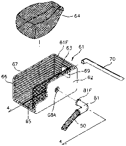
Système central de nettoyage par aspiration qui possède un tube pourvu d'une buse au niveau de son orifice d'entrée et destiné à aspirer de l'air contenant de la poussière, un porte-filtre connecté à un orifice de sortie du tube par un orifice d'entrée du porte-filtre pour filtrer l'air aspiré, un tuyau d'admission connecté par son orifice d'entrée à un orifice de sortie du porte-filtre et servant au passage de l'air filtré, un boîtier d'admission d'air installé sur un site à nettoyer et un orifice de sortie du tuyau d'admission connecté amovible au boîtier d'admission d'air, et une machine dotée d'un moteur et destinée à aspirer par la force l'air à travers le boîtier d'admission d'air. L'orifice d'entrée du tuyau d'admission est connecté pivotant au porte-filtre.


Abrégé anglais


A central vacuum cleaning system capable of preventing the
pipes from accumulating the collected matter is provided. In
the central vacuum cleaning system, a tube has a nozzle at an
inlet of the tube for sucking air containing dust. A filter
carrier is connected with an outlet of the tube by an inlet of
the filter carrier for filtering the sucked air. A net is
provided in the filter carrier adjacent to the inlet of the
intake hose. A plurality of grooves are provided in the housing
of the filter carrier where the filter is contacted. An intake
hose IS connected with an outlet of the filter carrier by an
inlet of the intake hose for serving as a passage of the filtered
air. An air intake box is installed at a place to be cleaned and
an outlet of the intake hose detachably connected with the air
intake box. A machine unit has a motor for forcedly sucking air
through the air intake box.

Revendications

Note : Les revendications sont présentées dans la langue officielle dans laquelle elles ont été soumises.


7
THE EMBODIMENTS OF THE INVENTION IN WHICH AN EXCLUSIVE
PROPERTY OR PRIVILEGE IS CLAIMED ARE DEFINED AS FOLLOWS:
1. A central vacuum cleaning system comprising:
a tube having a nozzle at an inlet of the tube for
sucking air containing dust;
a filter carrier connected to an outlet of the tube by
an inlet of the filter carrier for filtering the sucked air;
an intake hose for serving as a passage of the filtered
air, the intake hose being connected to an outlet of the
carrier at its inlet;
an air intake box installed at a place to be cleaned
and an outlet of the intake hose detachably connected to the
air intake box;
a machine unit having a motor for forcedly sucking air
through the air intake box; and
a swivel contact provided at a swivel connecting
portion between the inlet of the intake hose and the filter
carrier and connecting an electric wire leading from the air
intake box with a switch member of the filter carrier for
actuating said motor.
2. The central vacuum cleaning system according to claim
1, wherein the filter carrier has a housing and a filter
detachably provided in the housing of the filter carrier.
3. The central vacuum cleaning system according to claim 1,
wherein a net is provided in the filter carrier adjacent to
the inlet of the intake hose.
4. The central vacuum cleaning system according to claim 3,
wherein a plurality of grooves are provided in the housing of
the filter carrier where the filter is contacted.
5. The central vacuum cleaning system according to claim 1,
wherein the inlet of the intake hose is connected with a first

8
plate of the housing, the first plate is provided at a
location perpendicular to a direction of an air flow running
along the tube.
6. The central vacuum cleaning system according to claim
5, wherein the inlet of the intake hose is shaped as an elbow.
7. The central vacuum cleaning system according to claim
5, wherein the inlet of the intake hose is connected with the
filter carrier by a swivel connection.
8. The central vacuum cleaning system according to claim
5, wherein a second plate of the housing is symmetrically
arranged to the first plate with respect to a turning axis
located between the plates, the turning axis extending in an
up and down manner.
9. The central vacuum cleaning system according to claim
1, wherein the inlet of the intake hose is connected with a
rear portion of the housing, the rear portion is provided at a
direction parallel to an air flow running along the tube.
10. The central vacuum cleaning system according to claim
9, wherein the inlet of the intake hose is shaped as an elbow.
11. The central vacuum cleaning system according to claim
9, wherein an elbow is provided at the rear of the housing,
and the inlet of the intake hose is connected with the elbow
by a swivel connection.
12. The central vacuum cleaning system according to claim
11, wherein a swivel switch is provided at the swivel
connecting portion and is connected to the electric wire
leading from the air intake box with the switch member of the
filter carrier.

9
13. The central vacuum cleaning system according to claim
1, wherein a hook is provided at the housing of the filter
carrier for holding a rolled up intake hose when not in use.
14. The central vacuum cleaning system according to claim
1, wherein a backer is provided at the tube for supporting the
tube when not in use.
15. The central vacuum cleaning system according to claim
2, wherein a flap valve is provided at the inlet of the filter
carrier for preventing the dust caught in the filter from
overflowing.
16. A central vacuum cleaning system comprising:
a tube having a nozzle at an inlet of the tube for
sucking air containing dust;
a filter carrier connected to an outlet of the tube by
an inlet of the filter carrier for filtering the sucked air;
an intake hose for serving as a passage of the filtered
air, the intake hose being connected to an outlet of the
carrier at its inlet;
an air intake box installed at a place to be cleaned
and an outlet of the intake hose detachably connected to the
air intake box;
a machine unit having a motor for forcedly sucking air
through the air intake box;
a swivel contact provided at a swivel connecting
portion between the inlet of the intake hose and the filter
carrier and connecting an electric wire leading from the air
intake box with a switch member of the filter carrier; and
wherein the inlet of the intake hose is shaped as an
elbow and the inlet of the intake hose is swively connected to
the tube.

Description

Note : Les descriptions sont présentées dans la langue officielle dans laquelle elles ont été soumises.


CA 02338338 2001-O1-22
WO 00/04814 PCT/KR98/00222
1
CENTRAL VACUUM CLEANING SYSTEM
TECHNICAL FIELD
The present invention relates to a central vacuum
cleaning system, particularly to a central vacuum cleaning
system having a filter carrier connected with a tube of a
cleaning brush by an intake hose.
$ACKGROUND ART
In general, a central vacuum cleaning system consists of
a power generating part 200, a dust collecting part 300,
pipes 400, a linker 500, connecting hose 600, and a cleaning
unit as shown in FIG.8.
The cleaning unit sucks air containing dust in a room,
and the intaken dust flows toward the linker 500 through the
connecting hose 600. The linker is installed at a
predetermined position(for example, a wall) at a place to be
cleaned. The dust flowing toward the linker 500 goes through
the pipes 400 toward the power generating part 200 and the
dust collecting part 300, wherein the power generating part
200 is integrally formed with the dust collecting part 300.
The power generating part 200 receives electric power and
generates a suction :Force caused by the rotation of a
motor(not shown), and the dust collecting part 300 having a
filter filters the collected matters from the intake air
containing dust.
In the central vacuum cleaning system, as the refuse
intaken with the air containing dust in the cleaning unit 700
is sucked through the connecting hose 500 and pipes 400 and
is filtered at the filter in the dust collecting part 300,
the central vacuum cleaning system has a problem. After
prolonged, the collected matters accumulate at the curved
portion of the pipes 400, and thus the pipes become clogged.
As the dust collecting part 300 is integral with the
power generating part 200, the radius of the pipes 400 and

I6L88 ZW I~~/~S1 Li~:~T ~ 00, TT/~0
S'r'i KR9~ /00222
t,f J. f_ti'.,. V
a
the connecting hose 600 must be long for sucking the air containing
dust.
Also, as the cleaning unit 700 is directly connected to the
connecting hose 600, during the cleaning the weight of the
connecting hose 600 is a, burden upon the user.
DISCLOSURE OF INVENTTON
Therefore, it is an object of the presEnt invention, for tree
purpose of solving the above mentioned problems, to provicte a
central vacuutr, cleaning system capable of preventing the pipes
from accumulating the collected matter, which has the pipes and
the connecting hose having a small radius, and which allows easy
cleaning by tre user.
In order to attain the object, according to the present
invention, there is provided a tube having a nozzle at an inlet of
the tube for sucking air containing dust;
a filter. carrier connected wish an outlet of the tube by an
inlet of the filter carrier for filtering the sucked air, a net is
pioviJed in the filter ca:crier adjacent to the inlet of the intake
hose, and a plurality of grooves are provided in the housing of
the filter carrier wherE= the filter is contacted;
an intake hose connecting with an outlet of the filter carrier
by an inlet of the intake hose for sez~ving as a passage of the
fzltered air;
an air intake box installed at a place to be cleaned and an
outlet of the intake hose detachably connected with the air intake
_ box; and
a machine unit having a motor for forcedly sucking air through
the air intake box.
BRTEF DESCRIPTION OF dRl-1WINGS
. " _:.' ,~s~EE~
CA 02338338 2001-O1-23
~0 : SJdd SOS b~b~S Z ~t~+ : O1 WtiN'BWdN : WOb~ 6~ : 0~ ~1~-fION-e00~

IBL88 2W ~~/~S) L~:~I t~ 00, TT/~0
r .'
r
L
'Ty
FIG. 1 shows a using condition of a central vacuum cleaning
system according to tree present invention;
FIG. 2 is an enlarged exploded view of an embodiment of a
filter carrier of a cen.t:ral vacuum cleaning system according to
the present invention;
FIG. 3 is a partially cut-away perspective vieN of the
filter carrier shown S.n FIG. 2;
FIG. 4 is a sectior,~, view showing along line 4-4 in FIG. 3;
FIG. 5 is an enlarged perspective view of another embodiment
of the filter carrier as shown in FIG. 2;
CA 02338338 2001-O1-23
b0 : ~Jdd SOS b~b~S I ~b+ :O1 WtJN'BWtiN : W02~~ 0b :02 ~0-~OhJ-0000

CA 02338338 2001-O1-22
WO 00/04814 PCT/KR98/00222
3
intake hose is connected to a tube through an elbow;
FIG. 7 shows a condition of the tube and filter carrier
when not in use; and
FIG. 8 shows a using condition of the conventional
central vacuum cleaning system.
BEST MODE FOR CARRYING OUT THE INVENTION
The preferred embodiment of the present invention will
hereinafter be described in detail with reference to the
accompanying drawings.
A central vacuum cleaning system according to the present
invention is shown in FIG. 1. The central vacuum cleaning
system has a tube 70 for sucking air containing dust, a
filter carrier 60 for filtering the air intake through the
filter carrier 60, an intake hose 50 for flowing the filtered
air through the filter carrier 60 to an air intake box 40,
and a machine unit 20 :for forcedly sucking air collected at
the intake hose 50 through the pipes 30.
The filter carrier 60, as shown in FIGS. 2 and 3, has a
hook 86 for easily moving the filter carrier 60 under the
condition that the tube 70 and the intake hose 60 are
connected to the filter carrier 60, and a switch member 88
connected with the electric power for actuating a motor(not
shown) of the machine unit 20 is installed at the hook 86.
Further, the filter carrier 60 has a housing 61 and a filter
64 detachably provided in the housing 61. The housing 61 has
an intake inlet 69 formed at a front face 61F of the housing
61 for sucking air containing dust through the tube 70 inward
to the housing 61 and an outlet 68A formed at right plate 62
for providing dust-filtered air from the intaken air.
A flap valve 63 is hinged inside the housing 61 forming
the intake inlet 69 thereon. Also, a net 65 is provided
inside the housing 61 .at a predetermined distance from the
right plate 62 having the outlet 68A. A plurality of grooves

CA 02338338 2001-O1-22
WO 00/04814 PCT/KR98/00222
4
66 are provided at each inner face of the housing 61 except
the right plate 62 for guiding the air when the filter 64 is
directly contacted to each plate of the housing 61 during the
suction process.
An elbow 81 is installed between the intake hose 50 and
the outlet 68A of the right plate 61 for swivel contacting
the intake hose 50 with the right plate 62 of the filter
carrier 60. As shown in FIG. 4, a swivel contact is provided
at a swivel connecting portion 90 at which the elbow 81 is
connected to the right plate 62 of the filter carrier 60. The
swivel connecting portion 90 has an inner ring 93, an outer
ring 91, an inner contact portion 94, and an outer contact
portion 92. The inner and outer rings 93, 91 are made of
copper and are provided around the outlet 68A. The inner and
outer contact portions 94, 92 are formed at the front end of
the elbow 81 and are contacted to each of the inner and outer
rings 93, 91. Each of the inner and outer rings 93, 91 is
connected to the switch member 88 of the hook 86 by electric
wire(not shown). The inner and outer contact portions 94, 92
are connected to the motor(unshown) of the machine unit 20.
On the other hand, the left plate 67 is symmetrically
arranged to the right plate 62 with respect to a turning axis
X-X between the plates for the user's convenience, in which
the turning axis extends in an up and down manner.
FIG. 5 shows another embodiment of the filter carrier 60,
in which the intake hose 50 is connected to the rear portion
61R of the filter carrier 60. In this embodiment, after the
outlet 68A of the housing 61 is connected to the other elbow
85, the elbow 81 is connected to the elbow 85. At this time
an electric contacting portion is provided at the elbow 85
for driving the motor(not shown) of the machine unit 20 by
the operation of the switch member 88. That is, the inner
contact portion 94 and the outer contact portion 92, as
previously described in the first embodiment of the present
invention, are provided at the front portion 85F of the elbow

i ~ i ~ .. i
CA 02338338 2004-12-O1
S
85 connected to the outlet 68A. On the other hand, the inner
ring 93 and the' outer ring 91 are provided .at the rear
portion 85R connected to the elbow 85.
The operation of the central vacuum cleaning system as
described above will be described below.
When the user turns on the switch member 88 formed at the
filter carrier 60, the motor(liot shown) of the machine unit
20 operates. The titter carrier 60 receives air containing
dust through the tube 70 caused by the suction force of the
motor. At that time, the flap valve 63 in the filter carrier
60 opens, so air containing dust flows in the filter 64.
Dust-filtered air exhausts to the outside of the filter 64
and flows toward the outlet 68 along a number of grooves 66
in the housing 61. During the intake process, the filter 64
distends, but the net 65 is installed adjacently with the
outlet 68 controls to distend the filter 64, that is, the net
65 prevents the outlet 68 from being filled up by the filter
64.
When the user grasps the hook 86 of the filter carrier
60 and moves forward and backward for cleaning the place to
be cleaned, the user does not bear the weight of the intake
hose 50 because the intake hose 50 swivelly connected to the
right place 62 freely rotates. The swivel contact portion 90
prevents the cleaning system .from breaking the electric power
when the intake hose 50 is rotated, that is, the electric
power can be provided to the cleaning system when in use.
FIG. 6 shows the following condition. that the filter
carrier 60 is removed. The tube 70 is connected to the elbow
85, the other end of the elbow 85 is connected to the elbow
81, and the other end of the elbow 81 is connected to the
intake hose 50. This connecting condition is provided for
only sucked air containing dust when the place to be cleaned
is filled witY: the foul air.
After the cleaning process, the user detaches the intake
hose 50 from the intake box 40 as shown in FIG. 7, and holds

CA 02338338 2001-O1-22
WO 00/04814 PCT/KR98/00222
6
the rolled up intake hose 50 on the hook 86 of the filter
carrier 60, and the tube 70 is safely supported by the backer
73.
According to the present invention, since the filter is
installed between the tube and the intake hose, dust is
filtered by the filter, so air without dust flows to the
machine unit through the intake hose. Therefore, the present
invention prevents the intake hose from being filled up by
the collected dust.
Also, since only air without dust flows through' the
intake hose, the radius of the intake hose can be small, and
the user can clean the place to be cleaned without
inconvenience because the intake hose is swivelly connected
to the filter carrier.
While the invention. has been described with reference to
specific embodiments, the description is illustrated and is
not to be constructed as limiting the scope of the invention.
Various modifications and changes may occur to those skilled
in the art without departing from the spirit and scope of the
invention as defined by the appended claims.

Dessin représentatif
Une figure unique qui représente un dessin illustrant l'invention.
États administratifs

2024-08-01 : Dans le cadre de la transition vers les Brevets de nouvelle génération (BNG), la base de données sur les brevets canadiens (BDBC) contient désormais un Historique d'événement plus détaillé, qui reproduit le Journal des événements de notre nouvelle solution interne.

Veuillez noter que les événements débutant par « Inactive : » se réfèrent à des événements qui ne sont plus utilisés dans notre nouvelle solution interne.

Pour une meilleure compréhension de l'état de la demande ou brevet qui figure sur cette page, la rubrique Mise en garde , et les descriptions de Brevet , Historique d'événement , Taxes périodiques et Historique des paiements devraient être consultées.

Historique d'événement

Description Date
Le délai pour l'annulation est expiré 2010-07-22
Lettre envoyée 2009-07-22
Inactive : TME en retard traitée 2008-08-14
Lettre envoyée 2008-07-22
Accordé par délivrance 2007-04-17
Inactive : Page couverture publiée 2007-04-16
Préoctroi 2007-02-01
Inactive : Taxe finale reçue 2007-02-01
Un avis d'acceptation est envoyé 2006-08-24
Lettre envoyée 2006-08-24
Un avis d'acceptation est envoyé 2006-08-24
Inactive : Approuvée aux fins d'acceptation (AFA) 2006-06-28
Modification reçue - modification volontaire 2005-10-25
Inactive : Dem. de l'examinateur par.30(2) Règles 2005-04-27
Lettre envoyée 2004-12-29
Requête en rétablissement reçue 2004-12-01
Exigences de rétablissement - réputé conforme pour tous les motifs d'abandon 2004-12-01
Modification reçue - modification volontaire 2004-12-01
Inactive : Abandon. - Aucune rép dem par.30(2) Règles 2003-12-18
Inactive : Dem. de l'examinateur par.30(2) Règles 2003-06-18
Inactive : Page couverture publiée 2001-05-01
Inactive : CIB en 1re position 2001-04-25
Inactive : Acc. récept. de l'entrée phase nat. - RE 2001-04-05
Inactive : Inventeur supprimé 2001-03-29
Demande reçue - PCT 2001-03-27
Modification reçue - modification volontaire 2001-01-23
Toutes les exigences pour l'examen - jugée conforme 2001-01-22
Exigences pour une requête d'examen - jugée conforme 2001-01-22
Déclaration du statut de petite entité jugée conforme 2001-01-22
Demande publiée (accessible au public) 2000-02-03

Historique d'abandonnement

Date d'abandonnement Raison Date de rétablissement
2004-12-01

Taxes périodiques

Le dernier paiement a été reçu le 2006-07-21

Avis : Si le paiement en totalité n'a pas été reçu au plus tard à la date indiquée, une taxe supplémentaire peut être imposée, soit une des taxes suivantes :

  • taxe de rétablissement ;
  • taxe pour paiement en souffrance ; ou
  • taxe additionnelle pour le renversement d'une péremption réputée.

Les taxes sur les brevets sont ajustées au 1er janvier de chaque année. Les montants ci-dessus sont les montants actuels s'ils sont reçus au plus tard le 31 décembre de l'année en cours.
Veuillez vous référer à la page web des taxes sur les brevets de l'OPIC pour voir tous les montants actuels des taxes.

Historique des taxes

Type de taxes Anniversaire Échéance Date payée
Taxe nationale de base - petite 2001-01-22
Requête d'examen - petite 2001-01-22
TM (demande, 2e anniv.) - petite 02 2000-07-24 2001-01-22
TM (demande, 3e anniv.) - petite 03 2001-07-23 2001-07-16
TM (demande, 4e anniv.) - petite 04 2002-07-22 2002-07-17
TM (demande, 5e anniv.) - petite 05 2003-07-22 2003-07-14
TM (demande, 6e anniv.) - petite 06 2004-07-22 2004-07-22
Rétablissement 2004-12-01
TM (demande, 7e anniv.) - petite 07 2005-07-22 2005-07-11
TM (demande, 8e anniv.) - petite 08 2006-07-24 2006-07-21
Taxe finale - petite 2007-02-01
TM (brevet, 9e anniv.) - petite 2007-07-23 2007-07-11
TM (brevet, 10e anniv.) - petite 2008-07-22 2008-08-14
Annulation de la péremption réputée 2008-07-22 2008-08-14
Titulaires au dossier

Les titulaires actuels et antérieures au dossier sont affichés en ordre alphabétique.

Titulaires actuels au dossier
HEUNG-MOOK KANG
Titulaires antérieures au dossier
S.O.
Les propriétaires antérieurs qui ne figurent pas dans la liste des « Propriétaires au dossier » apparaîtront dans d'autres documents au dossier.
Documents

Pour visionner les fichiers sélectionnés, entrer le code reCAPTCHA :


Pour visualiser une image, cliquer sur un lien dans la colonne description du document. Pour télécharger l'image (les images), cliquer l'une ou plusieurs cases à cocher dans la première colonne et ensuite cliquer sur le bouton "Télécharger sélection en format PDF (archive Zip)" ou le bouton "Télécharger sélection (en un fichier PDF fusionné)".

Liste des documents de brevet publiés et non publiés sur la BDBC .

Si vous avez des difficultés à accéder au contenu, veuillez communiquer avec le Centre de services à la clientèle au 1-866-997-1936, ou envoyer un courriel au Centre de service à la clientèle de l'OPIC.


Description du
Document 
Date
(aaaa-mm-jj) 
Nombre de pages   Taille de l'image (Ko) 
Dessin représentatif 2001-04-30 1 7
Description 2001-01-22 7 288
Abrégé 2001-01-22 1 24
Revendications 2001-01-22 3 90
Abrégé 2001-01-21 1 43
Description 2001-01-21 6 274
Revendications 2001-01-21 3 97
Dessins 2001-01-21 8 132
Description 2004-11-30 7 284
Revendications 2004-11-30 3 111
Revendications 2005-10-24 3 114
Dessin représentatif 2006-10-26 1 22
Avis d'entree dans la phase nationale 2001-04-04 1 202
Courtoisie - Lettre d'abandon (R30(2)) 2004-02-25 1 168
Avis de retablissement 2004-12-28 1 170
Avis du commissaire - Demande jugée acceptable 2006-08-23 1 162
Avis concernant la taxe de maintien 2008-09-01 1 171
Quittance d'un paiement en retard 2008-09-01 1 164
Avis concernant la taxe de maintien 2009-09-01 1 171
PCT 2001-01-21 4 175
PCT 2001-01-22 3 146
Correspondance 2007-01-31 1 35